Close
0%
0%

nodeLED

WiFi controller for RGB/RGBW Analog LED strips

Similar projects worth following
As a hacker, I know all too well how much workbench space is vital. Alongside my three monitors, I have an extended desk that houses my soldering irons, compartment shelving, and countless projects, amongst other tools and devices. One constant that seems to get in my way is an old desk lamp. That’s where this project came to light, ha! I decided to design my own lamp using an analog RGBW LED strip. This board I designed will give you the tools to design your own WIFI controlled light source.

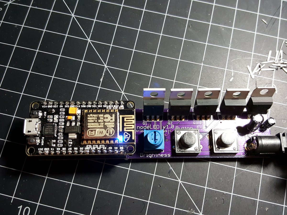
The board’s controller is run by the NodeMCU which is connected to a N-Channel MOSFET for each color of the RGBW LED strip. Trimpot for brightness and 2 user buttons (that can be setup to change modes, possibly) were also added. A 5v regulator was then added so the power can be shared with 9-12v input for the LED strip. The nodeMCU will be wirelessly updatable as well.


My idea is to have the nodeMCU be a web server for direct control via a web page. The site will have various configurations including color options, number of channels, animations (like fade effects) and a timer. I’d like to have it connect to MQTT server to integrate with larger servers such as openHAB.

nodeLED_V1.0_schematic.png

Schematic for 1.0

Portable Network Graphics (PNG) - 25.00 kB - 05/22/2016 at 15:52

Preview
Download

  • 1 × RGBW Analog LED Strip
  • 1 × Angle Aluminum 1in x 1/16in x 36min (Cut to length as needed)
  • 1 × OSHPark PCB
  • 1 × nodeMCU esp8226 with USB
  • 4 × IRLB8721 Discrete Semiconductors / Power Transistors and MOSFETs

View all 11 components

  • Parts

    MobileWill05/29/2016 at 21:22 0 comments

    Here is a picture of the parts that will go into mounting the nodeLED and the LED strip on my desk. It will be attached to my desk’s shelf with two mending plates and four small L-brackets. Originally I wanted to avoid screwing into the wood of the shelf. My idea was to flip the L-brackets so that they hang on the sides, but they aren’t stable or even long enough with my drawers on top. So after fandangling them around, I will now screw them in from under the shelf. Hopefully the screws can handle the weight, which shouldn't be too much. After that’s done, I’ll attach the aluminum corner L-strip which will support the LED strip and rest on a screw and nut on the end of the mending plates.


  • Up and Running

    MobileWill05/29/2016 at 06:50 0 comments

    I went ahead and took the plunge and flashed a new nodeMCU. The replacement works just fine but I hope after a few hours it doesn’t do it again. Afterall, there are only so many extra nodeMCUs and it takes forever to order more. The only thing I can think of is that I left the heatsink off the regulator since it was running off 7.4v battery instead of the normal 12V supply. But the regulator would have been damaged, I would think. It’s a strange one!

  • Dead nodeMCU

    MobileWill05/27/2016 at 06:10 1 comment

    This past weekend I had a chance to demo the nodeLED at the MakerFaire Hackaday meetup and at OSH Park’s Bring-A-Hack. I wasn’t sure if I would have power, so I decided to use a 7.4V LiPo I had from an old project. It wouldn’t be full brightness but enough to demo. During the first meetup, I left it running on the table but after some time passed, I noticed it was off and the regulator was quite toasty. I quickly unplugged it. Dead battery was my initial reaction. Especially after I had plugged it in again, the esp8266 LED seemed to flutter and go out. But by using the handy USB Tester with the DC Tester, I could tell the battery wasn’t dead because it dropped straight to <1v when plugged into the nodeLED. So something else was going on if the battery cutoff was triggering. Also, I didn’t get to demo it at the Bring-A-Hack! Bummer!

    I can’t leave a problem unsolved so upon arriving home from the weekend away, I tested the nodeLED with a 12v wall-wart. Um yeah, I about burned myself on the regulator! I should've known better, especially if the battery was cutting out. I also noticed if I plugged the nodeMCU into my computer, the onboard user LED would only illuminate very dimly, also becoming a bit toasty.


    Following up a couple of days later, I did some more testing and I could tell that the nodeLED itself is fine; the regulator is healthy. The problem lies with the nodeMCU, which is very strange. I plan on investigating the cause further, but for now, and in the interest of time, I will have to use another nodeMCU. Good thing I have extras!

  • PCB Test

    MobileWill05/13/2016 at 00:33 0 comments

    The PCB has finally arrived and I can start testing and writing code. Here are some pictures of the PCB and a simple LED color test.

View all 4 project logs

Enjoy this project?

Share

Discussions

cschrisstarke wrote 05/21/2016 at 18:30 point

Hello which pins on the nodeMCU do you use to control the FETS? I have a similar project but am having an issue where a colour randomly goes on, and am wondering if perhaps I'm using pins used for other purposes such as wifi

  Are you sure? yes | no

MobileWill wrote 05/22/2016 at 15:53 point

I added the schematic as a file attachment to the project. Hope that helps. Let me know if you any questions. 

  Are you sure? yes | no

Similar Projects

Does this project spark your interest?

Become a member to follow this project and never miss any updates