 Yann Guidon / YGDES
Logs:
1. How does it work ?
0%
0%
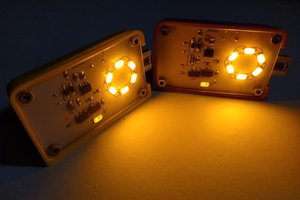
Lampounette
Just a last minute cute hack before I went to a camping trip in summer 2009.
Become a Hackaday.io member
Already have an account? Log in.
Just one more thing
To make the experience fit your profile, pick a username and tell us what interests you.
Pick an awesome username
hackaday.io/
Your profile's URL: hackaday.io/username. Max 25 alphanumeric characters.
Pick a few interests
Projects that share your interests
People that share your interests


 Simon Merrett
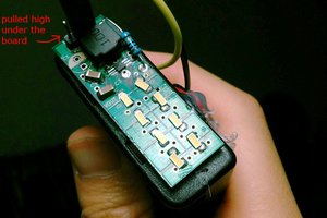
 drojf
drojf
 Ted Yapo
 hkdcsf
Did you measure the battery capacity? Your battery looks like the BRC type, which could be a fake, it is listed here as a fake battery:
http://danyk.cz/test18650_en.html
Instead of the claimed 5000 mAh, he measured only 426 mAh for the BRC brand.
I got a similar battery, brand name "GIF", also only about 500 mAh. The seller claimed an impossible high capacity of 9900 mAh:
https://www.eevblog.com/forum/dodgy-technology/9900-mah-18650-accus/msg2725094/#msg2725094
And there are sellers who offer 12000 mAh batteries, crazy. Real capacity was 1500 mAh. Still searching for a high quality genuine 3000 mAh 18650 battery.