The problem:
I have suffered for years with a poor ADSL connection being over 5km to my nearest exchange, and constantly had dropouts and irregular speeds between 1.5Mbps and 3Mbps. I used a Billion 7800N modem which has the Broadcom DSL chipset (the most tolerant to long lines) and the Billion could adjust a number of the ADSL settings which helped tweak the speed but you can' t beat physics so it was a constant battle of compromises between reliability and speed. With a family of three teenagers who love to stream music and movies you can imagine the frustrations with the internet connection. In Australia with long distances and sprawling suburbs it is fairly common to have marginal ADSL connection, and fibre / cable is only an option for some suburbs, not mine.
When my ISP Optus had a long line outage once they gave us a mobile wireless broadband hotspot to tide us over for a few days but being in a mobile phone blackspot I knew it wouldn't work well, and I only got a marginal connection and slow speeds with the hotspot only picking up a faint signal at one location in the house. So along with the high costs of wireless broadband in Australia with low data caps, it seemed wireless broadband wouldn't be an answer for me.
Recently a local wireless ISP VividWireless released a LTE broadband product with unlimited downloads at a reasonable price, the only Australian wireless ISP to do this (that I know of), which solves the issue of low data caps. And when I checked their site it showed that I wasn't in coverage range (not unexpected) but not too far away from their coverage edge. They used the Optus wireless network and have a local cell tower not too far away which I knew would get a signal albeit a poor one as my hotspot can just pick it up. They also limit the speed of the wireless connection to 10/1 Mbps which isn't fast for LTE however it goes a long way to not overloading the limited bandwidth of the cell tower - having unlimited downloads and fast LTE speeds at a good price is a recipe for a popular service especially in a suburb like mine where ADSL is marginal, making a wireless service attractive and quickly congested. So its good that this is a speed limited service - 10Mbps is 4x as fast as I typically get on ADSL and if it is more reliable then it may be an option if I can solve the reception issue.
Being a qualified (but not practicing) Electronics Engineer and remembering sitting through all those boring (and maths intensive) 4th year lectures about antenna theory and radar that I never got to use in practice I thought - why not have a go at trying my hand at a DIY antenna? So I took the plunge and bought the wireless modem and signed up to a month of the service - worst case I could resell the modem if I couldn't get it to work. Installing and setting up the wireless modem I had the same experience as the hotspot (as expected), barely working in only one spot in the house and very marginal (RSSI -91dBm), about 3Mbps with dropouts, likely worse when it rains. Spending a day trying different spots in the house did locate a place on the roof where it would receive -89dBm and if raised the modem high enough on that spot I got -83dBm which should be sufficient for a fast and reliable signal, and with a proper antenna I might even be able to get in the -70's.
Antenna options
Easiest option would be to buy an antenna however it seems the LTE frequency the ISP uses 2310 - 2400 Mhz isn't a popular one, adjacent to the 2.4Ghz wifi spectrum, but sufficiently different that an antenna designed for wifi wouldn't be as sensitive or effective as one specifically designed for the Optus / Vivid spectrum. There don't seem to be any antennas specifically designed for the 2300Mhz LTE band although there are a lot of wide bandwidth antennas that span this range, but I recall from my lectures on antenna theory that bandwidth and gain are a tradeoff so that large bandwidth wouldn't be high gain (even if advertised as such - seems lots of false claims about antenna performance especially on dubious sites like eBay). Also as the cable run from the high spot on the roof to the communications cupboard in my house is at least 6m, so I should expect some loss from the cable and connectors that the antenna gain would need to make up for.
The ISP's modem does have a SMA connector for an external antenna (2 actually - diversity antennas) so I did try a 2.4Ghz whip antenna I had from a wifi router and it didn't do as well as the internal antenna (no surprise here). I also tried the 'windsurfer' reflector that is a popular hack on the net to boost reception of wifi routers using a cardboard template glued with tinfoil on one side acting as a parabolic reflector that focuses the wifi signal onto the whip antenna. Again no improvement and no connection to the cell tower. What about the cheap Yagi's on ebay / aliexpress for $5 - could they be hacked to work? From the results folks have posted on the net they haven't been designed well for 2.4Ghz let along 2300Mhz - you are better off using the internal wireless modem antenna.
OK - need to get serious if this is going to work as it is evident that the wireless modem has a decent internal antenna and I'll need the best antenna I can muster, which will need to be DIY as a higher gain antenna for this LTE band can't be purchased (not that I could find). So doing some internet research and recalling those antenna lectures from years back a quad or Yagi antenna would give the highest gain, ideally with a parabolic dish. I could get the most gain from a directional antenna but didn't want something ugly propping up from my roof either so the parabolic dish is out (wind gusts on a dish could also push the antenna out of alignment dropping the signal). One advantage of a yagi at these frequencies is that the antenna is small making it easier to make / mount and immune to wind movement.
Designing a 2300Mhz Yagi
So a Yagi meets the criteria of not being too bulky, fairly stealthy and not too hard to build. It doesn't look too complex being a number of elements on a boom, can't be that hard to design and setup right? Like most things electronic what looks simple on the surface has layers of complexity that you peel like the skin on an onion. There are many things to consider:
- Gain
- Front / back performance
- Directionality
- Bandwidth
- Impedance matching
I was also surprised that there wasn't a first principles analysis where you could apply a mathematical formulae to design the antenna, most of the software on the net for Yagi design use an empirical approach and are based on a set of tables made from measurements of real world yagi performance and scaled to suit the frequency and bandwidth. A Yagi is a complicated system to model mathematically due to a large number of interacting factors that make the empirical approach more practical.
In general when designing a Yagi:
- The more elements in Yagi, the higher the gain but the more directional it becomes.
- Gain is also improved with a boom of longer length and more spacing between the elements.
- The bandwidth is affected by the spacing between the elements as well as the diameter of the elements.
After a lot of reading I realised that designing a Yagi was an iterative process and required several approaches to arrive at the final design. I settled on 2 programs from ham radio enthusiasts:
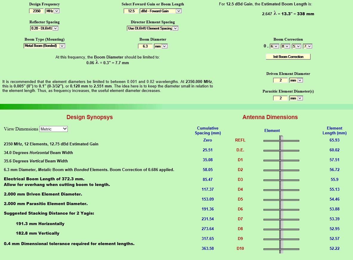
1) Martin E. Meserve K7MEM has a set of javascript programs based on commonly used Yagi measurement tables to design a Yagi for a given frequency as well as some excellent design guidance (eg. acceptable range of the boom and element diameters based on frequency). This gives you a starting point for an initial Yagi design based on frequency, number of elements and a couple of other relevant parameters including the balun specification (to match the coax impedance to the antenna impedance). Using K7MEM's site I could design a Yagi design for 2350Mhz (midpoint of the LTE frequency band) with 12 Elements and 12.75 dBd Estimated Gain.
Link: http://www.k7mem.com/Electronic_Notebook/antennas/yagi_vhf.html#Page_Top
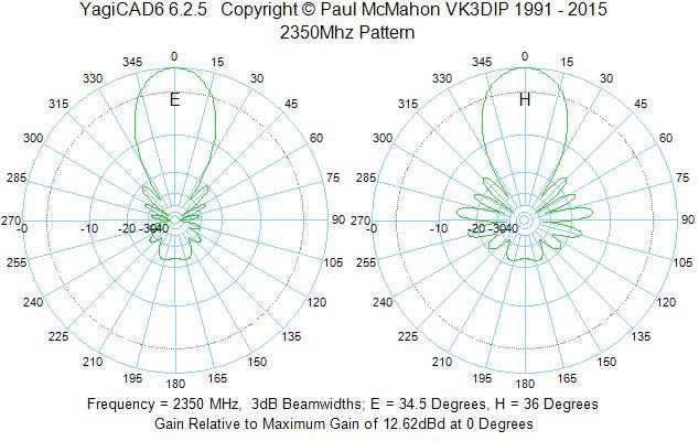
2) However this design isn't enough as it doesn't allow tuning for bandwidth or impedance, and further modelling is needed to get to the optimal antenna design. For this a more sophisticated modelling program is needed, and the 2 most common ones are MMANA-GAL and 4NEC2. Both have their pros and cons (and a rather steep learning curve for the uninitiated) and I chose to use a nice front end to 4NEC2 called YagiCAD from Paul McMahon VK3DIP, a windows program that makes it easy to model by entering your Yagi's element size and spacing then you can run simulations and optimisations on it for bandwidth, gain and impedance. The starting 2350 Mhz Yagi design from K7MEM's model didn't simulate very well with only about 7dB of gain and a sharp drop off at higher frequencies even within the LTE spectrum with unstable impedance, definitely not optimal.
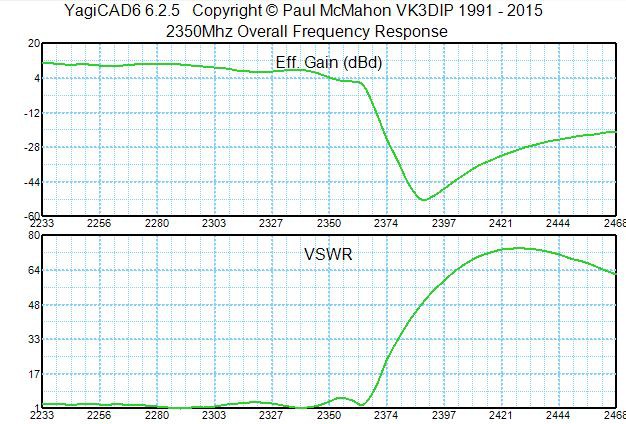
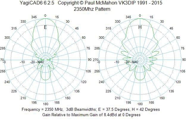
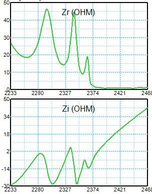
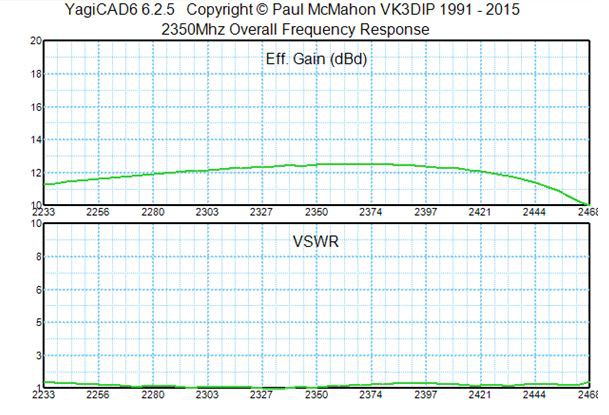
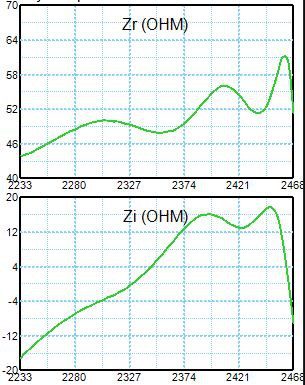
YagiCAD allows you to optimise for gain which adjusts the element length and spacing and the updated design ended with 12.5dBd gain but still horrible bandwidth and impedance performance. Another optimisation option to adjust bandwidth and impedance is called genetic optimisation and it uses random 'mutations' of your design and tests those for the bandwidth, gain and impedance targets you set, ranking the mutations and picking the best one. This one is then passed through the randomiser again to produce more mutations to test and rank, and so on. After several runs lasting 5 minutes each the law of diminishing returns kicks in and there are no more improvements. It's rather impressive seeing this run and viewing the testing of mutants, and the end result is significantly better with an almost flat bandwidth from 2300Mhz - 2400Mhz for the same 12.5dBd gain as well as smoother impedance over the range making the antenna easier to match to the coax line. Adjusting the gain and bandwidth alters the element size and spacing and the optimised antenna isn't radically different from the K7MEM with element lengths 10% - 20% different but some of the element spacing is quite different.
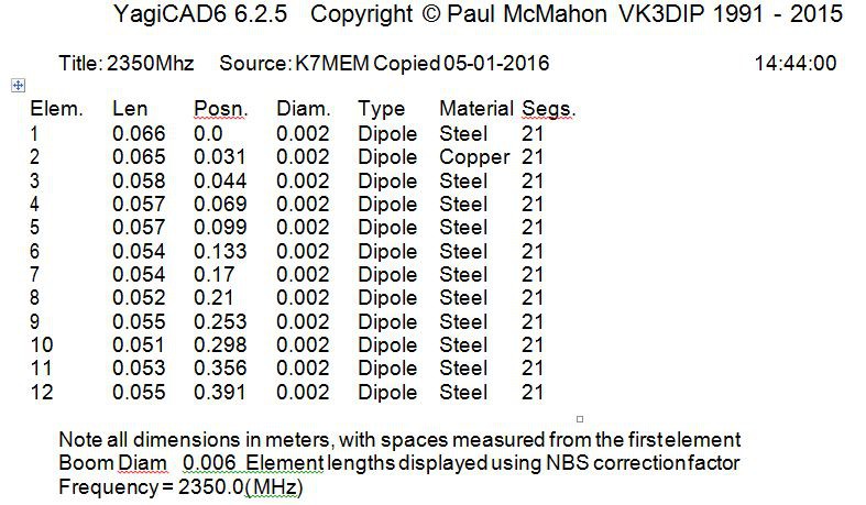
Here is the outcome of the optimisation from YagiCAD, a much smoother response, consistent gain and 50 ohms impedance. Basically a better antenna.
The end result measurements for the antenna:
Link: http://www.yagicad.com
Coax and Matching
Next comes the balun, which is used to match the impedance of the driven element to the coax (50 ohms). Most internet yagi designs use a folded dipole for the driven element which is 300 ohms impedance and needs a balun, usually a 1/2 wavelength section of coax that adjusts the phase of the signal effectively changing the impedance.
Link: http://www.k7mem.com/Electronic_Notebook/antennas/yagi_vhf_feed.html
However as my Yagi optimised by YagiCAD has almost perfect impedance over the 2300 - 2400 LTE band, no balun is needed and I can use a normal dipole as the driven element for a 50 ohms match. This makes assembling the antenna a little easier however I still need to convert from the dipole's balanced configuration to the unbalanced coax line (the shield being earth), and to do that I used a Pawsey stub. Similar to a balun, it is a 1/4 wave length of coax with the stub shield connected to the feed inner conductor at the dipole junction and the other end connected to the feed coax shield. It works by mirroring the feed current in the stub effectively making the dipole think its connected to a balanced cable.
Link: http://www.dg7ybn.de/Symmetrising/Symmetrising.htm
The cable and connectors are another important aspect of the design, and due to the high frequencies and small signals involved the choice of cable can make or break your solution and is much more sensitive to cable compared to your TV set. It's not sufficient to use garden variety TV coax, a lower loss cable is important especially if you have a long run of coax, and in my case from the apex of the roof to the communications cupboard where the modem is stored is about 6m.
 (link: http://x.net.au/wifi-antenna-cable/)
I used RG213 which was the best coax my local electronics store had, so with 6.5m of cable @50dB loss / 100m = 3.3dB of loss expected. Don't forget there is also losses with the connectors, and I didn't use a connector on the Yagi but required a RG213 connector plug and a RG213 to SMA adaptor, likely losing another 1.5dB or so loss through the terminations and connections between the coax and the modem radio circuitry.
Lastly the polarisation orientation (plane) of the signal in the cell tower needs to be taken into account. The majority of phone towers in Australia use vertical or slant polarisation (45 degrees, axial). Initially mount the Yagi so that it's elements are vertical and not horizontal / flat. If slant is in use the tower likely has two slant antennas at + and - 45 degrees, so the best starting point is still vertical. The difference in loss you might get between slant and vertical will be approximately 3dB - the reason behind this is because mobile antennas are vertical, the opposite of most TV antennas which are usually horizontally polarised. My ISP Optus / Vividwireless use slant polarisation and I got the best signal with the yagi orientated left side up, right side down.
In Australian If you want to the polarisation of your tower then you can look it up on the ACMA web site by using the cell tower location name on the site [here].Last thing to remember about the cabling and mounting is that you should not have metal near the yagi as it will affect the reception, usually for the worse. I used a 30mm piece of plastic plumbing conduit and a plastic handle to mount the Yagi.