 Jon Thomasson
I’ve been working more on writing firmware to test the transceiver modules. Although I couldn’t locate any ready made libraries to drive this particular IC, there were a few none the less that helped to guide me in the right direction. Those libraries were the RF69 library by Lowpower Lab, as well as the Radiohead library. These libraries interfaced with a similar model transceiver, the SX1231, which was also designed by Semtech.
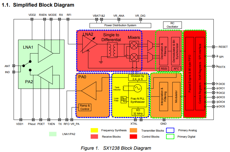
One of the features of the SX1238 that intrigued me was that it included not one, but two low noise amplifiers on its receive, as well as two power amplifiers on its transmit. These added amplifiers should not only make it easier to detect weak signals, but should also give the transceiver a theoretical longer range as compared to the SX1231. Here is a view of the block diagram for the SX1238 showing how the internals are laid out.
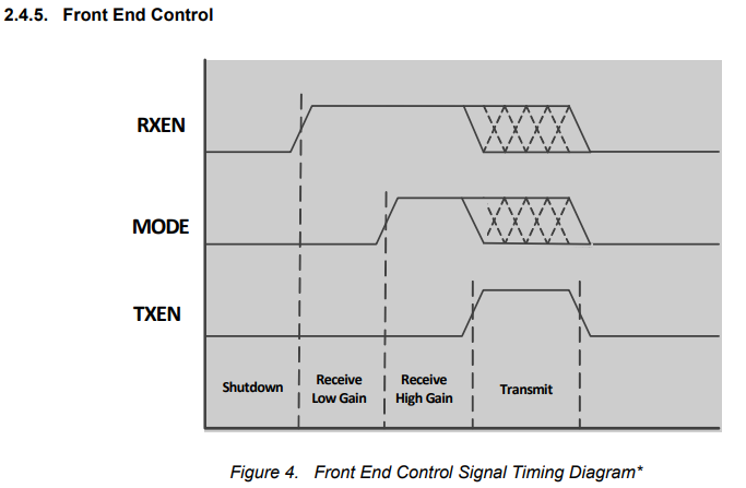
These added amplifiers, PA2 and LNA1, are turned on/off through three front end control pins, TXEN, RXEN, and MODE. The operation of these pins through the different transmit/receive modes can be seen here:
Interfacing with these pins was of course just a matter of connecting the appropriate pins on the transceiver module to the arduino and then toggling them during the transmit and receive sequence.
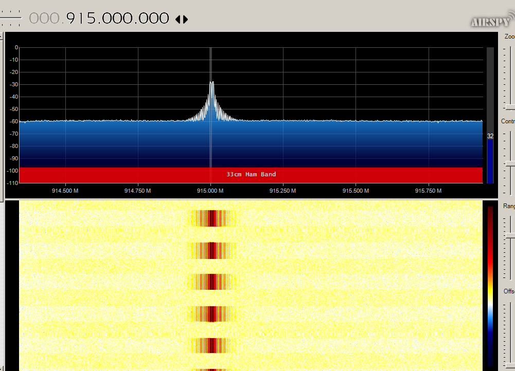
To test the transmitter I used a cheap RTL-SDR dongle and the free SDR Sharp software. I just wrote a simple sketch which transmits a packet once a second and looked for the signal to show up somewhere on the FFT plot. It was a thrill to see the signal pop up on the screen for the first time! It was alive!
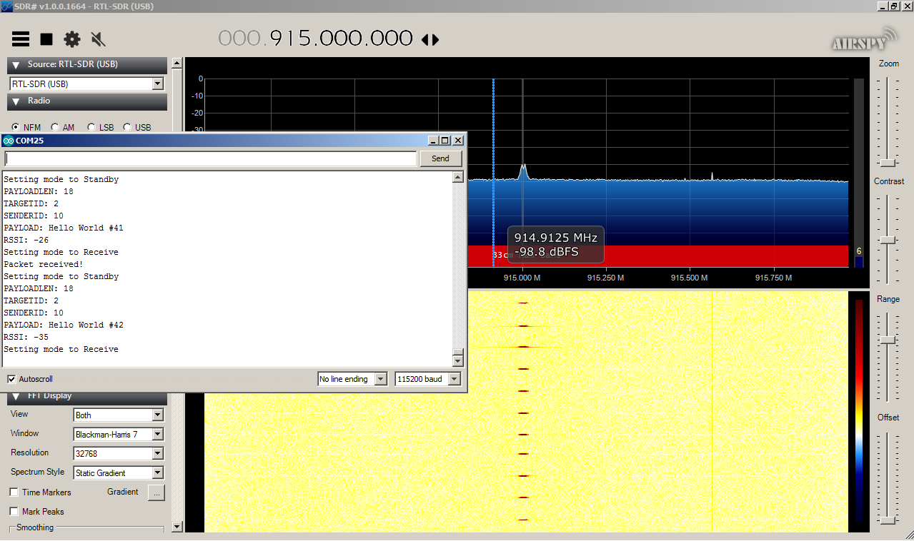
After this euphoria, I thought setting up the receiver would be the easy part. Boy was I wrong! The firmware for the receiver was setup to simply listen for incoming packets from the transmitter, and then print those packets out to the serial monitor. The excitement was nearly unbearable the first time I uploaded the firmware to the receiver. Expecting to see a rush of packets fill the serial monitor screen, instead there was nothing. Just a blank screen. The roller coaster thrill ride came crashing down and hit with reality.
There was an onslaught of doubt in my mind after this initial test. Maybe there was something wrong with the pcb, or perhaps there was a faulty solder connection somewhere. It was obvious that something was being transmitted since the signals were being picked up by the SDR Sharp software. However, maybe the actual transmission was just garbage.
After taking a break for a bit and getting some air, I decided to dig through the datasheet again and analyze my code a bit more. This digging led me to discover a peculiar register named RegFifoThresh that had as one of its variable names TxStartCondition. TxStartCondition, as its name implies, determines the state at which the transmitter would begin transmitting packets from the FIFO. By default this register was set to only transmit after a specified FIFO threshold had been passed. Since I wanted the transmitter to transmit whenever there was a new packet in the FIFO, I changed this default value to allow the transmitter to transmit whenever the FIFO was not empty. After making this modification and uploading the firmware once again, I started to see a few packets being received and printed out on the monitor. However, the packets weren’t consistent, and the data wasn’t recognizable. But it was progress!
I ended up experimenting for some time with all the various filters and frequency shaping registers. It was fascinating just to make some changes to a few registers and see how it affected the look of the signal in SDR Sharp. I finally cleared the registers pertaining to the frequency deviation of the signal, and reset it to its default parameter. And low and behold, I started receiving packets! I had modified these register values when porting some of the code from the other libraries into my own. It’ll require a bit more experimentation to see what the optimal frequency deviation will for various bit rates, but for now at least I know the design works!
As with all projects, you tend to learn more from the things that don’t work the first time. And this project was no exception. I’d like to think that I have a new appreciation for RF, and just how delicate a balance it can be to get things to behave just right. My oldest daughter and I are in the process of studying for our HAM radio licenses (I currently hold a Novice class) and it was educational for us to see the correlation between these things (frequency deviation, bandwidth, side band) we’re reading about, and viewing them live via the SDR software.
Discussions
Become a Hackaday.io Member
Create an account to leave a comment. Already have an account? Log In.