 T. B. Trzepacz
I've got a terrible cold this week, so I thought I might catch up with some past updates.
I FINALLY found a source for minikey sized keybeds at the NAMM show, a company I had attempted to contact through AliBaba before, but never got a response from. It turns out AliBaba shakes them down for money for the contact info, which they didn't want to pay, so I couldn't get through. Next time, look up their company name and go direct!
So, I bought one of their keybeds as a sample while I was there, and disassembled it quickly when I got home.
Here it is, intact.

Note key pitch is again slightly wider and less long than my design.


It was quickly disassembled...


But the connectors have a pin pitch that won't fit in my breadboard.

I determined that the connector pins would fit nicely on the edge of a circuit board.


BTW: I had made some necessary changes to the Arduino keypad library, and submitted them to the owner. My changes exist on the GitHub version, but never made it into the Arduino Playground version for some reason. You can find it here: https://github.com/Nullkraft/Keypad
The changes are to add the key state to the event listener for keypad events, so if you are doing real-time checking of keys, you can tell if the key was pressed or released without having to search through the internal data structures for the key. I still left the original event listener so that older code would not be messed up, but it would have been nice to just remove that stuff completely and make the internals "private".
Anyway, having finally decoded the keyboard, I have created this lovely schematic. It is missing the diodes, tho.
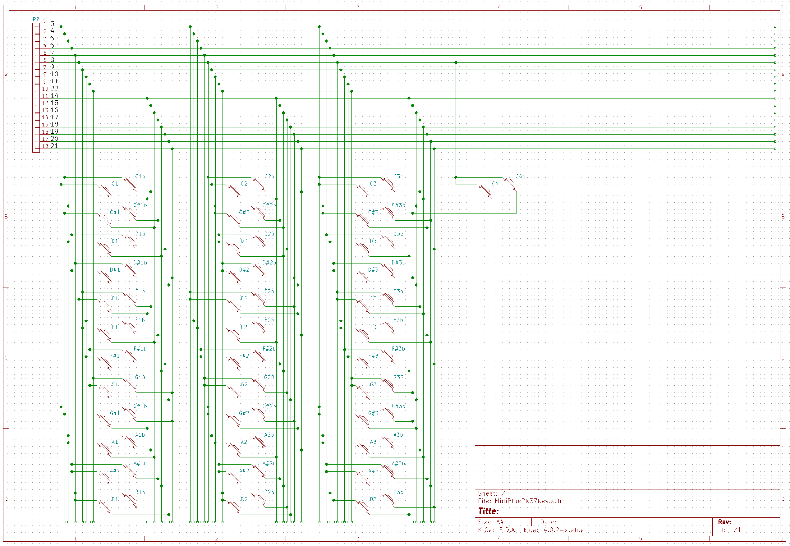
I broke it down by octave and noted each key name. I might have some of the "b" versions of the key reversed... I don't really have a good way to know which is which at this point (no logic analyzer...) but I am sure that will become apparent when I finally write the library.
Discussions
Become a Hackaday.io Member
Create an account to leave a comment. Already have an account? Log In.