0%
0%
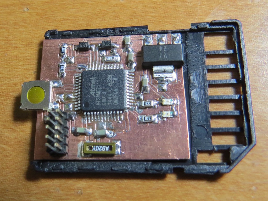
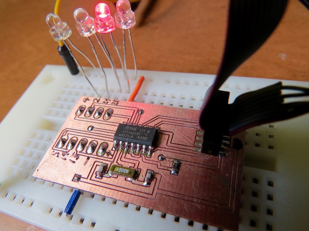
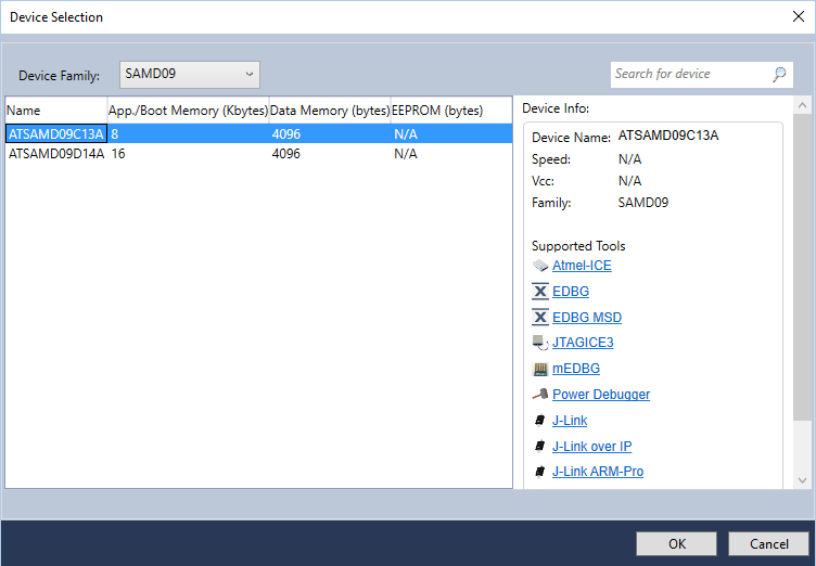
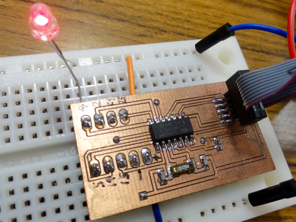
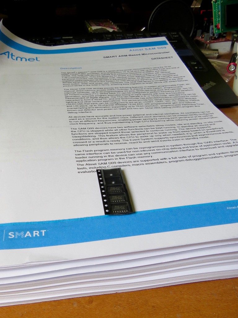
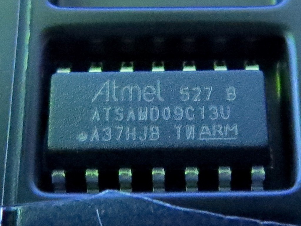
Minimalist goes Atmel Smart D09
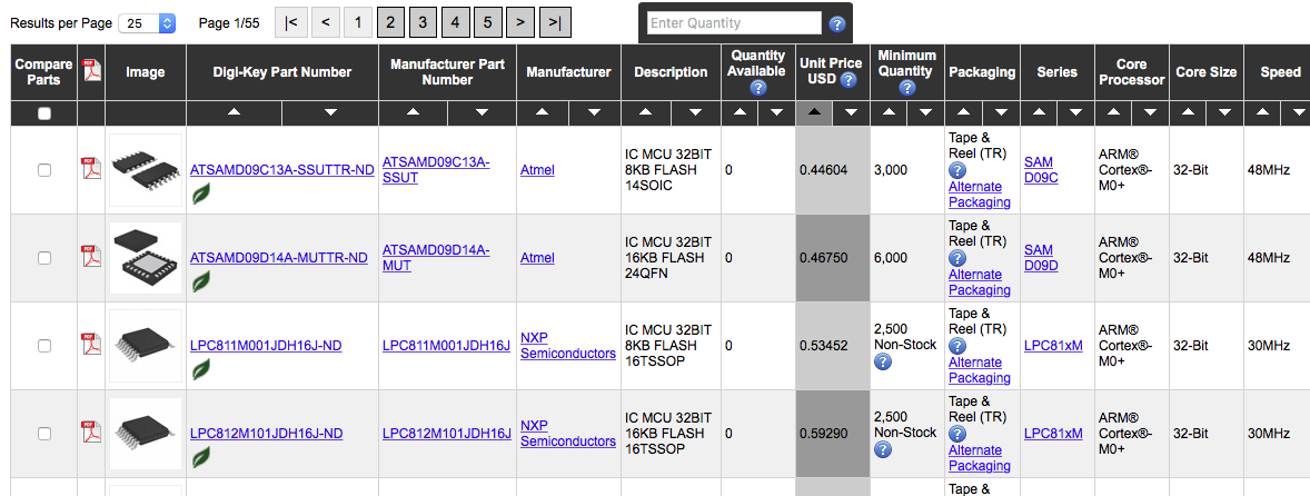
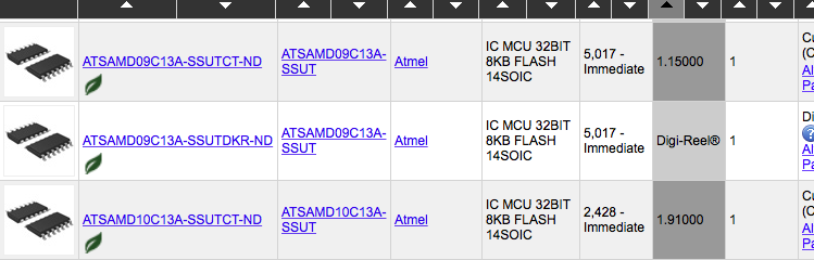
Now I would put one step forward to Atmel ARM series by very low price SAMD09
 kodera2t
Become a Hackaday.io member
Already have an account? Log in.
Just one more thing
To make the experience fit your profile, pick a username and tell us what interests you.
Pick an awesome username
hackaday.io/
Your profile's URL: hackaday.io/username. Max 25 alphanumeric characters.
Pick a few interests
Projects that share your interests
People that share your interests


 John
John
 Christoph
 Electroniclovers123
I want to know how you have burned boot loader? I have problem in burning boot loader.