0%
0%
Holoscope - Superresolution Holographic Microscope
Subpixel imaging using the Raspberry Pi and an Android Smarthpone. The lightsource is represented by an LCD.
 beniroquai
Become a Hackaday.io member
Already have an account? Log in.
Just one more thing
To make the experience fit your profile, pick a username and tell us what interests you.
Pick an awesome username
hackaday.io/
Your profile's URL: hackaday.io/username. Max 25 alphanumeric characters.
Pick a few interests
Projects that share your interests
People that share your interests


 From the figures above it can be seen directly, that either the distance from the object to the sensor has to be small or the interference-partners have to be close together to get the required fringes.


 These fringes are coming from the interaction of the spherical waves coming from the LED-source with the transmission-function of the object. Therefore condition of coherence has to be fulfilled (temporal and spatical coherence). The LED is great, because it fits this circumstance and doesn’t produce any speckle pattern (color-spectrum ~20nm, high efficiency, small-chip~spatial-coherence)
 already, why not using them?
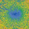

 Christian Walther
 Sir Michael II
 G.Vignesh
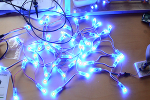
images removed?