 GearheadRed
I came up with this idea back in early 2012 and have been picking at it since. Ive had a prototype working since spring of 2013 and have put over 3,000 miles on the prototype. I was holding the concept back to try and patent and productize it but never really felt comfortable with the results of research on how interested people might be for such a product. I stuck with arduinos to encourage a hacker community but decided in the end releasing open source is the best way to encourage hackers, makers, and innovators alike.
My original main design goals were size, reliability, and cost.
Size is still a factor I am unhappy with and will continue to revise using different hardware.
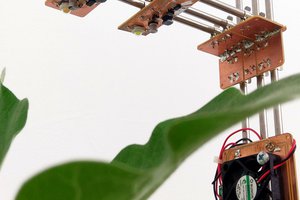
Reliability comes from the use of the light pipe instead of flexible LED strips or EL wire/panels. Flexible LED strips and EL wire can only sustain so much flexing and stretching before failure and I didnt feel that was acceptable. The light pipe works amazingly well and limits electrical components to only 2 LEDs and the flexible stranded wire routed through the jacket to power them.
Cost has been kept down to around $100 total(I think currently I am actually closer to $80) for the project not including motorcycle jacket of choice, the end goal was to be able to mass produce the configuration including the jacket for $150 or less to allow for a 30% wholesale markup for profit, and another 15% to 20% at retail while still retaining competitive pricing with other jackets($300 motorcycle jacket is still considered middle of the road for many). Not that this information is particularly useful to anyone now that the project is open source, it at least shows that it can be built and implemented without breaking the bank and it is within feasible manufacturing costs if someone wanted to take that endeavor on.


 timonsku
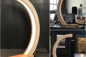
 todbot
 MDreamer
 Josh Starnes
so i'm really interested in this project and was wondering if you thought about using a textile jacket instead. Mounting the light pipe on the inside of the jacket instead of the outside. Would the light pipe be bright enough to shine through it? The only reason i'm considering this is so i don't ruin my leathers with stitching. something about stitching into my 700$ leather jacket doesn't sound good.