 Ted Yapo
IMPORTANT Info for DDL Builders
I've spoken with several people who are building things with DDL. If you plan to do so, please check this log entry early and often: I'm going to use it as a rolling errata and notes section as issues with the design or documentation are discovered. Reading this before you begin (and as new notes are posted) may save you some time and/or frustration.
Warning
DDL is an experimental idea. It relies on an undocumented and non-guaranteed property of the 1N4007 diode. You're not "supposed" to be able to do logic like this with diodes, so don't expect it to be perfect, or even easy. DLL has lousy fan-out, soft thresholds, and anemic gain. Don't use it for anything other than curiosities.
Also, start small. Build a board or two and play with them a bit before building enough for the whole clock (or whatever you are building). The gates can be connected temporarily (or semi-permanently) with 0.1" jumpers, sold cheaply everywhere. At the kHz frequencies the logic runs at, there is no performance penalty for long, messy wiring.
Inductor Sourcing
The original inductors designed-in on the DDL01 and demo board, Taiyo Yuden part number LAL02VD470K are no longer manufactured. Unfortunately, I don't think anyone still makes micro-miniature through-hole wound chokes with 0.1" (2.54mm) lead spacing in 2016. If you have already ordered boards, or soon will, you have several options:
Got Boards?
If you have already ordered boards, let me know, and I can probably send you some inductors from my stock, unless you need a ton of them.
Want the Original?
Some of the original parts seem to be available on ebay:
- 10/$1 US: http://www.ebay.com/itm/Lot-of-10-Ferrite-Inductor-47uH-70mA-/110709806763?hash=item19c6d196ab:g:hLQAAOSwPcVVifcF
- 8/$1.05 US: http://www.ebay.com/itm/8-pcs-47-uH-10-Inductors-by-Taiyo-Yuden-15B4d-/361551403801?hash=item542e249b19:m:mW8v_FJW6RDcXV90emYEB-g
There may be others. I have no affiliation with these sellers.
Substitutes
The cheapest current-production substitute part would appear to be the Bourns 78F470J-RC (78F470J-RC @ DigiKey). The part is $0.1128 US in 500 quantity. I have run preliminary tests on this part, and it seems to work so far, but as of today, 5/20/16, I have not had a chance to populate a full DDL01 board with these inductors and run thorough tests. I am hoping to be able to do so over the weekend. I will report the results here once I do.
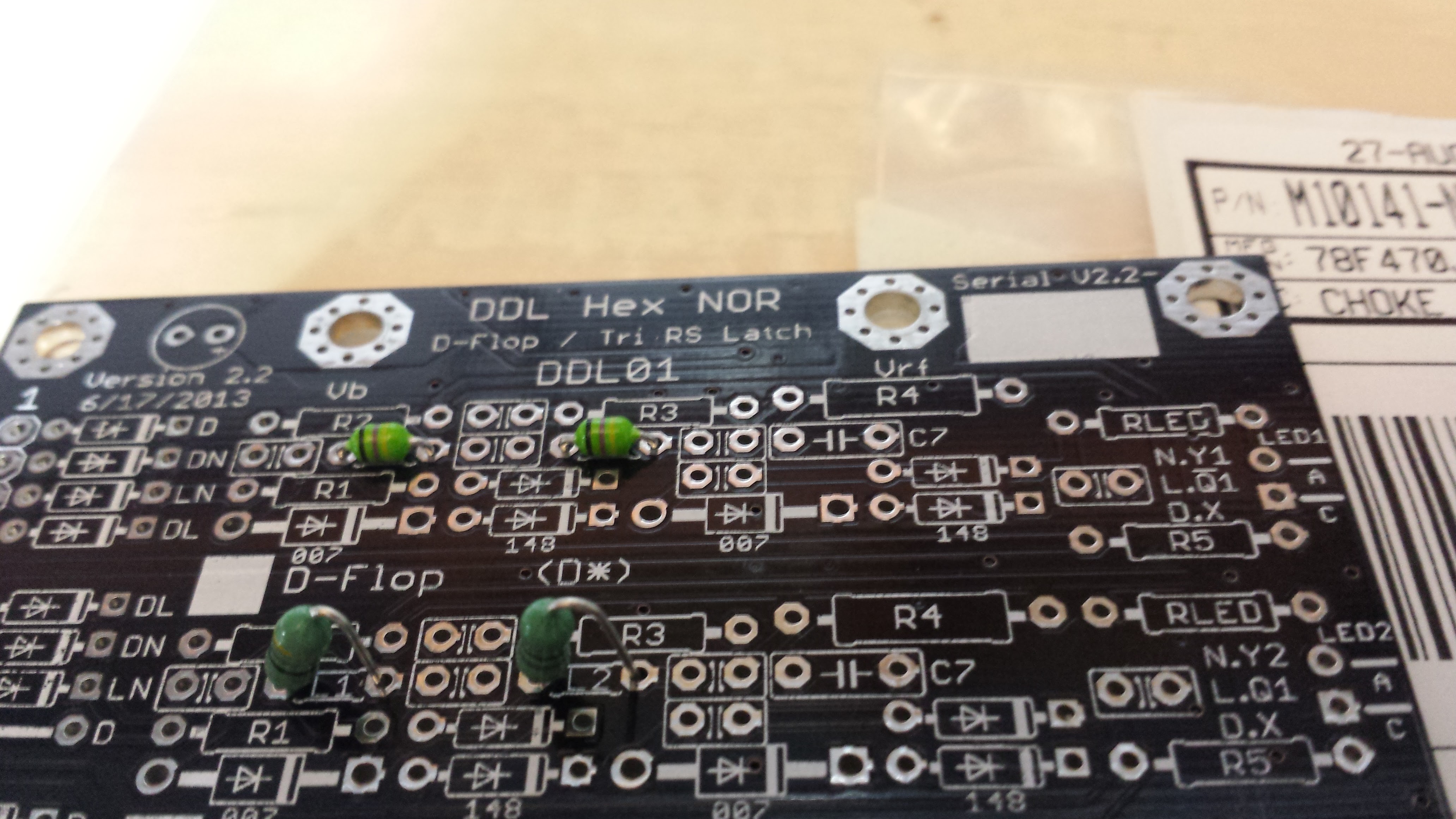
The only apparent downside to this part is its size. As shown below, the part is larger than the original inductor, so must be mounted (semi-) vertically on the board (original Taiyo Yuden parts on top, Bourns on bottom). I have confirmed that it easily clears the next board in a stack when assembled with the nominal 7/16" standoffs. In my clock build, the boards themselves cannot be seen without great difficulty, so I doubt anyone would ever notice these parts standing slightly proud of the others.
Going Forward
I will eventually re-spin the DDL01 and demo board to use the current-production 78F470J inductors. At the same time, I intend to add a "set" input to the flip-flop. This probably won't happen for a while, since I'd like to get a first pass at documenting everything else first. The Eagle files are open-source and shared on hackaday.io, so if you feel the need to modify them yourself, have at it.
Fragile Parts!
I am rough with parts when prototyping. I bend and solder and trim and unsolder and re-bend leaded parts over a copper clad groundplane until things work - this often takes many iterations. Before using these tiny inductors, I had never destroyed a passive component by such rough handling. But, I've destroyed literally dozens of the original tiny inductors. My suspicion is that they are wound with very fine wire that breaks easily if you bed the pins the wrong way - they always fail "open" with no outward sign of damage. It can be really frustrating. They are supplied with pre-formed leads for a reason. In populating over 50 DDL01 boards (600 inductors), I didn't have a single failure, though. I carefully clipped the parts off the ammo tape, stuffed and soldered them on the boards, then clipped the leads flush. If you use them, be careful.
Populating the DDL01 Jumpers
The DDL01 board can be configured at build-time as six NOR gates, three RS latches, or a single (negative) edge-triggered D flip-flop. Here's how. Next to each jumper or diode on the input row, there are one or more letters or "*". They mean this:
- D : populate for D-flop
- N : populate for NOR
- L : populate for Latch
- * : always populate
The silkscreen makes clear if there's a diode or jumper expected in each position. You can see these letters on the left hand of the board photo above, next to the input diode and jumper sites.
DDL01: R4
R4 on the DDL01 is a 1/2W unit - it dissipates more than you want on a 1/4W unit (less than 250 to maintain a 2x de-rating, though). All other resistors are 1/4W. R4 is 220 Ohms for normal gates (with front-panel LEDs) but I switched to 150 Ohms for boards driving the seven-segment displays to get better brightness. Since there are six displays, there are 6*7 = 42 segments, and you need 42/6 = 7 boards populated this way. The diodes on the DDL03 encoder ROM are also used as the input diodes for the segment driver boards - see below. I'll document this in more detail when I describe the display boards in a separate log entry.
Also note that there are six resistors designated "R4" on the board. In fact, all of the corresponding gate components are designated identically: "R4" means the same thing to each gate. Unconventional, perhaps, but I found it useful.
Segment Driver Boards
Seven DDL01 boards are specially configured as segment drivers for the clock display. As mentioned above, these boards are fitted with 150 Ohm 1/2W resistors at the six "R4" sites to boost display brightness. In addition, the performance is improved by eliminating the redundant input diodes on this board. Since the DDL03 encoder ROMs are already a diode input matrix for the display drivers, input diodes on the seven segment-driver boards are unnecessary and simply hurt performance. So, to improve things a bit, no input diodes are used on the segment driver boards. The "NOR" gate diode positions (indicated with an "N" next to the input diode sites on the DDL01) are simply populated with wire jumpers. This only applies to the seven boards used as segment drivers.
DDL01 Datasheet
You should probably approach anything in the datasheet with caution. The PIN-diode properties of the 1N4007 are not guaranteed by *its* datasheet (it's just a rectifier diode, after all), so depending on the manufacturer and lot, you might get better or worse (or no) performance in this application. I have never seen a 1N4007 (or 1N400x for that matter) that didn't work at some level, but you might run into them. For a good time, google "1N4007 PIN diode" and read what some of the hams have to say on the issue. I used Fairchild 1N4007 diodes in all my DDL circuits, although I have sampled other manufacturers. I suspect that some of the 1N400x series you may encounter are actually 1N4007s sold as lower-spec parts (like selling 1% resistors as 5%), but don't count on it.
Power Consumption
The whole clock consumes 60W (measured at the 12V DC supply input), regardless of the clock speed (it's not CMOS!). Roughly, this means that each board consumes 60/46 = 1.3W, and each gate 1.3/6 = 220mW.
RF Emissions
You are responsible for complying with any laws or rules concerning electromagnetic interference in your country or jurisdiction. Each DDL02 power supply can deliver 35W of RF power in the high-frequency band. Four such boards are used in the clock, enough to easily cause serious interference to other devices, including amateur radio, government, or emergency radio services in the HF band. An "open" case style can exacerbate the problem.
The clock uses a spread-spectrum approach (documentation forthcoming) to try to mitigate any emissions problems, but it has not been thoroughly tested as of now. By building or operating this device you may cause harmful interference and/or subject yourself to legal penalty. I don't run my clock for extended periods at the moment, and won't until I am sure it isn't emitting harmful interference.
Discussions
Become a Hackaday.io Member
Create an account to leave a comment. Already have an account? Log In.
It's a great project. Although I don't really understand its principles, I just want to build a complete clock. In your document, You said that I should start with a simple one instead of building a complete one directly. So where should I start?
Are you sure? yes | no
Maybe start with a simple latch.
https://hackaday.io/project/11677-the-diode-clock/log/37959-ddl-demo-board-and-simple-examples
If you're going to build one, it's probably best to gain an understanding of how it works - you're going to have to make changes somewhere. Try these PDF documents, in this order:
https://cdn.hackaday.io/files/11677499588768/ddl_backgounder.pdf
https://cdn.hackaday.io/files/11677499588768/ddl_demo_board_datasheet.pdf
https://cdn.hackaday.io/files/11677499588768/DDL01_datasheet.pdf
Also, I think I have the world's remaining supply of the specific inductors I used on the boards. Let me know if you need a box.
Are you sure? yes | no
what specific inductors you use?I am studying basic knowledge about diode。
Are you sure? yes | no
@sunny Taiyo Yuden part number LAL02VD470K
Are you sure? yes | no
I've studied your file. The inductance pitch seems to be 5MM? So the problem of inductance is only about size, not parameters? If it's a KICAD file, I think I can modify its size, but I can't do anything about eagle.
Are you sure? yes | no