 Ted Yapo
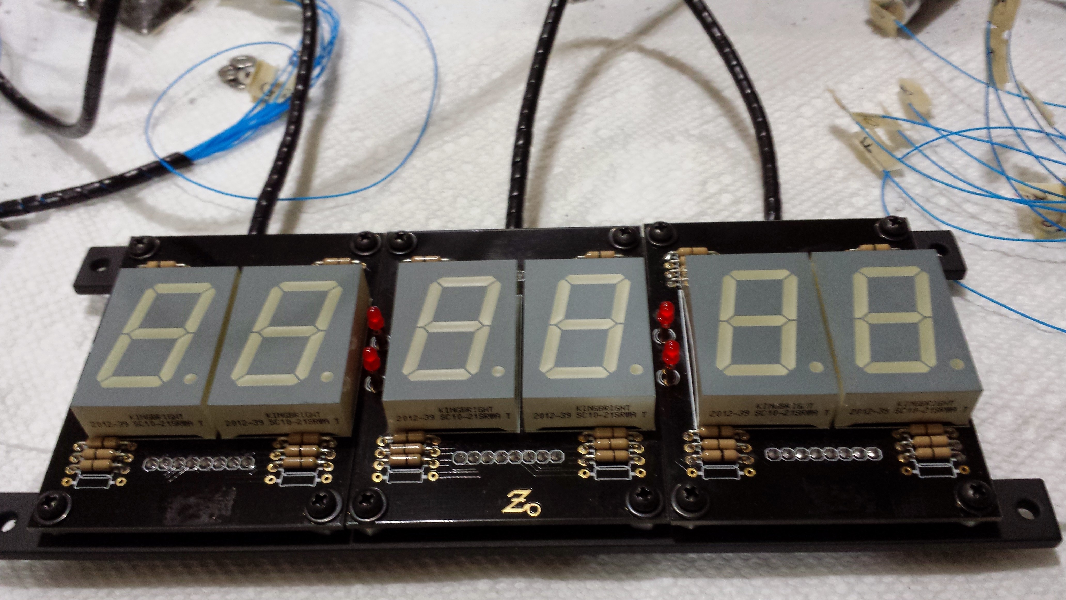
The clock face is made from three identical boards, shown here bolted to their aluminum mounting rails. The two rightmost boards have their colon LEDs populated, while the two outer boards have the bottom backlit logo painted over (quite poorly, I might add).
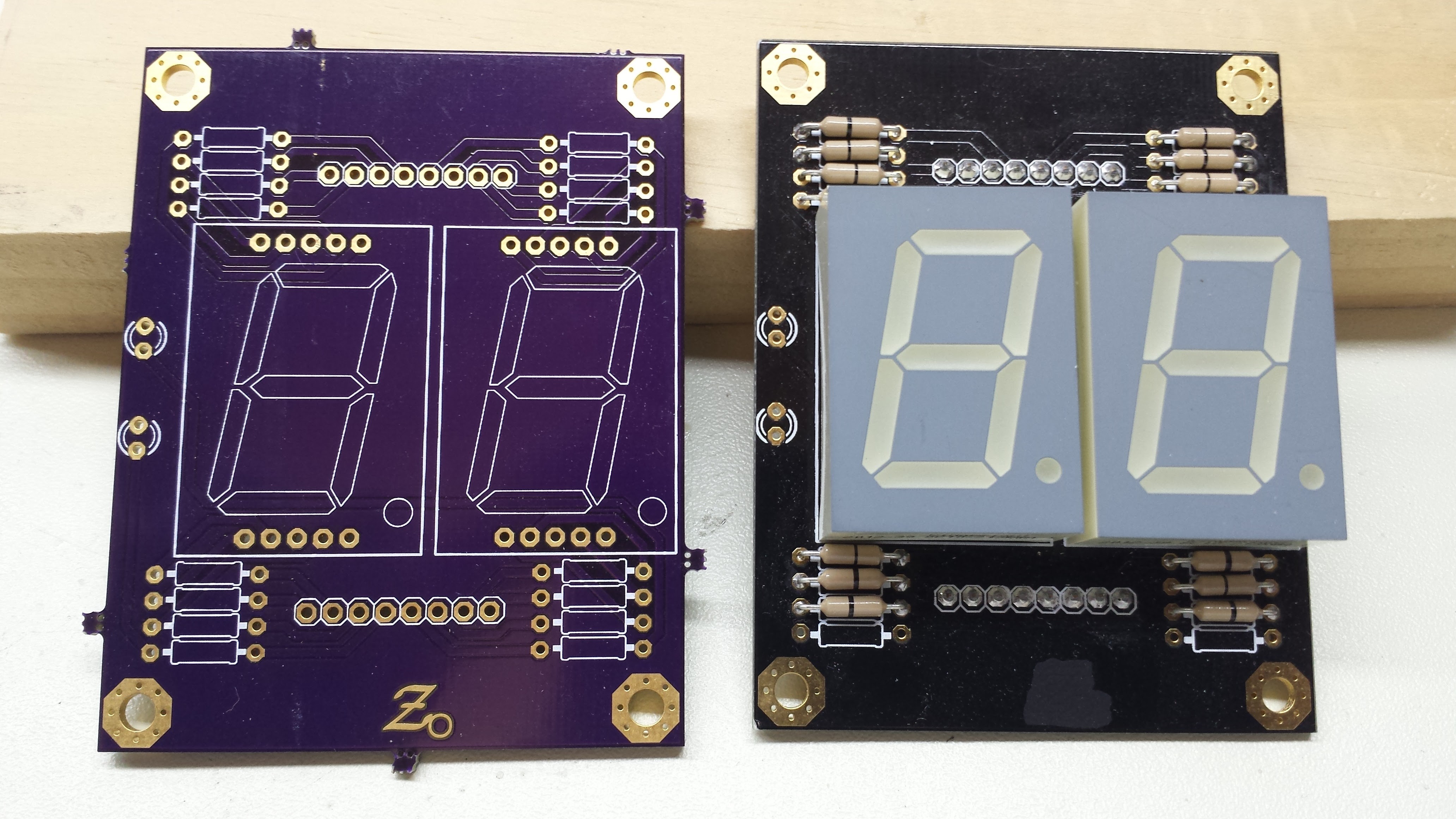
Here's a close-up. The board on the right was rejected because I soldered the displays on crooked. Tape them in place before soldering - a little folded paper in between can help keep the spacing uniform.
The "resistors" on the board are zero-ohm - when I designed the board, I wasn't sure if they'd be needed or not. As it turns out, the maximum output current of the DDL drivers (approx. 9mA) doesn't require any resistors. The unpopulated resistor sites on the bottom of the board are for the colon LEDs. When I assembled the board, I wasn't sure what values would be required to match the brightness of the colons to the displays. I determined this experimentally after the clock was up and running, and spliced resistors into wires running from the timebase 5V supply to the colon LEDs.
Header pins extend from the back of the board (soldered on the top side, directly above and below the displays).
Design Files
Gerbers are shared on OSH Park, and purple boards can be ordered there.
Eagle design files are here on hackaday.io.
BOM
Each display board requires the following parts:
- (2) Kingbright SC10-21SRWA 7-segment display SC10-21SRWA @ DigiKey
- (14) Zero-ohm resistors (suitable ones by Yageo @ DigiKey), or use wire jumpers
- (2) 3mm LED Kingbright WP710A10SRD-D WP710A10SRD-D @ DigiKey
- Header pins as desired for connections
Don't substitute the 7-segment displays unless you verify proper operation with your intended part. These displays are ultra-bright and efficient with a low forward voltage, so they can be driven easily by DDL gates. The efficiency of the colon LEDs is less of an issue, since they're lit by the 5V rail, but these particular ones are color-matched to the displays. The colon LEDs are mounted with small standoffs to match the height of the displays. I cut some pieces of tiny copper tubing to slip over the leads as spacers, but anything similar would work.
Next: DDL04 Spread Spectrum Exciter (and EMI tamer, hopefully)
Discussions
Become a Hackaday.io Member
Create an account to leave a comment. Already have an account? Log In.