 M. Bindhammer
Here is the first draft of the glucose meter schematic:
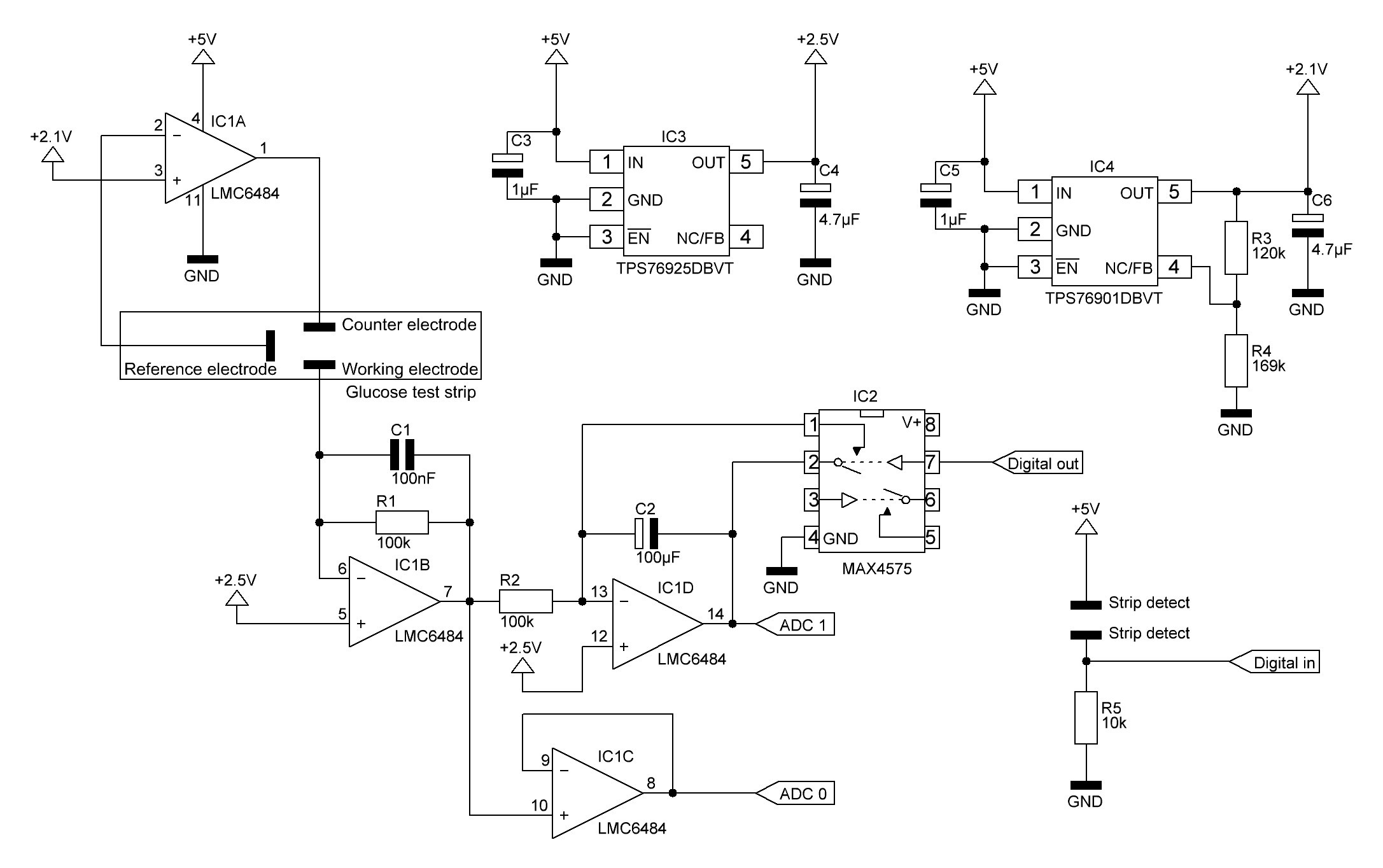
As the non-inverting input is not connected to GND (VR = 0V) but to VR = +2.5V:
Updated schematic:
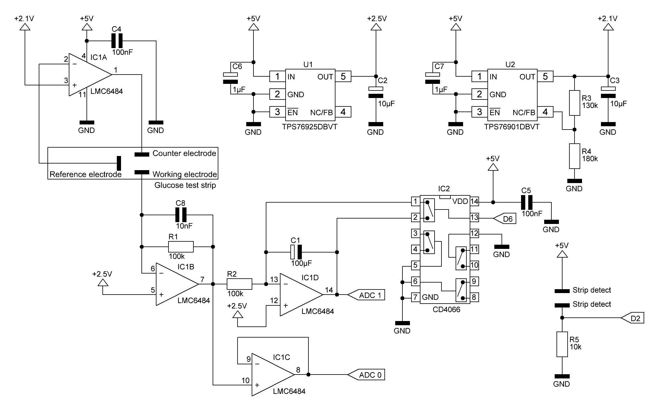
I changed the MAX4575, which resets the op amp integrator by shortening the capacitor by the quad bilateral switch CD4066 (IC2), because this chip is much cheaper. Because integration involves a known start time and end time, a reset circuit must be included to establish the start time before each integration time period. The integration end time occurs when the measurement is read. The CD4066 simply short-circuits the capacitor C1 if digital output D6 goes HIGH. The not used control inputs are tied to ground. Unused CMOS input pins must never be unconnected, because they tend to
float towards the dangerous region which is in the middle between VDD
and GND.
The low-dropout regulator TPS76925DBVT (U1) provides a fixed output voltage of 2.5V.
The output voltage of the TPS76901 adjustable regulator (U2) is programmed using an external resistor divider. The output voltage is calculated using:
Where: Vref = 1.224V typ (the internal reference voltage).
As the applied voltage across two of the test strip electrodes should be about 400 mV, I chose R3 = 130k and R4 = 180k which results in a TPS76901 output voltage of 2.108V.
As mentioned above IC1D is configured as an op amp integrator. Currently I don't use the op amp integrator because the op amp integrator output voltage is not directly or indirectly proportional to the glucose concentration when using ONETOUCH test strips. This might be the case when using other test strips.
IC1B is configured as a transimpedance amplifier, where basically
The feedback capacitor C8 is required to improve stability.
IC1A and IC1C are configured as unity gain buffer amplifiers. In this configuration, the entire output voltage is fed back into the inverting input. The difference between the
non-inverting input voltage and the inverting input voltage is amplified
by the op-amp. This connection forces the op-amp to adjust its output
voltage simply equal to the input voltage:
For IC1A this is only the case if an electrolytic bridge (blood) between the reference and counter electrode is applied.
As long as the strip is not inserted, input pin D2 is LOW. If a test strip is inserted, the two strip detect pins on the strip connector getting connected and D2 goes HIGH.
C4 and C5 are decoupling capacitors.
Discussions
Become a Hackaday.io Member
Create an account to leave a comment. Already have an account? Log In.
I'm having trouble simulating the test strip in Proteus. Can you please drop a link to a proteus file or a screenshot of it please? Thank you.
Are you sure? yes | no
Hello Bindhammer, can you please explain the significance of the integrator circuit (IC1D) and the IC2 circuit because I think the signal extracted from the ADC0 could be programmed to get the glucose concentration of a blood sample.
Thanks for your continous support.
Best regards
Are you sure? yes | no
Please take a look at 'Basic principle of operation' here: https://hackaday.io/project/11719-open-source-arduino-blood-glucose-meter-shield
and see above. Already explained.
Are you sure? yes | no
Thanks for your help, its much appreciated.
Best regards.
Are you sure? yes | no
No. IC1C just forward the output voltage of the transimpedance amplifier 1:1 to ADC0. I just configured IC1C as a voltage follower so all of the 4 op amps, the LMC 6484 chip is providing, are used.
U1/U2 are necessary to provide the according reference voltages and the difference between the reference voltages (approx. 400mV). You could also use voltage dividers instead but they are less accurate.
Are you sure? yes | no
Hello Bindhammer, Thanks for the quick response it was very helpful. I simulated the IC1A circuit on proteus software and I realised that the voltage entering the reference and counter electrodes are 2.50896V and 2.5V respectively. Can you please explain this part.
Can you please explain why IC1A pin 3 is assigned 2.1V and IC1B pin 5 assigned 2.5V.
Also is it true that the current generated due to the application of a blood sample on the test strip is fed to the working electrode?
Thanks for your anticipated response.
Best regards
Are you sure? yes | no
2.50896V and 2.5V seems to be close enough to be actually equal. The applied voltage across two of the electrodes needs to be around -400mV. 2.5V is used as reference, so we need to create another voltage source of approx. 2.1V. Current is 'fed' to the working electrode.
Are you sure? yes | no
Bindhammer you are a star, I will always appreciate your effort towards this project. Have got two questions please: Is IC1C amplifying the output voltage of the transimpedance amplifier (IC1B) and then feeding it to ADC0?
Secondly, was the U1 circuit and U2 circuit only showing how to get the 2.5V and 2.1V used on the amplifers?
Thanks for your unrelenting support.
Best regards
Are you sure? yes | no