 E. N. Hering
To guide the system development I followed some guidelines:
- A generic micro controller module should be developed.
- The connection between modules should follow some kind of standard, permitting them to communicate easily.
- The addition of extra hardware to a module should be easy. For that to be true, the generic module should make most of the popular interfaces available to a 'sub module' where the new hardware should be installed. This submodule should be plugged to the back of the generic module and that should be the only requirement for it to work.
- No module should have the same function as any other module on the system, unless redundancy was required.
I also wanted:
- Generic modules to be cheap and easily replaceable. I had to select a micro controller to use in them. Out of my ignorance I chose ATMega328p.
- Generic modules to be able to use different micro controllers, as long as they followed the same communication protocols and made available the same services to the sub modules, in the same pin order.
- Any hardware installed in the system to be easily replaceable by newer, better versions in a way that the rest of the system would not notice the difference between the new and the old one. Backward compatibility.
This sounds much like an Arduino, but with some basic differences:
- The ATMega328p micro controller has two SPI interfaces, but Arduino blocks one of them with the serial connection. I wanted both interfaces working: one to use as the main connection to other modules and the second one made available to any hardware installed in the submodule.
- I wanted every byte of flash and RAM available to the firmware, so the Arduino bootloader was not an option and was removed.
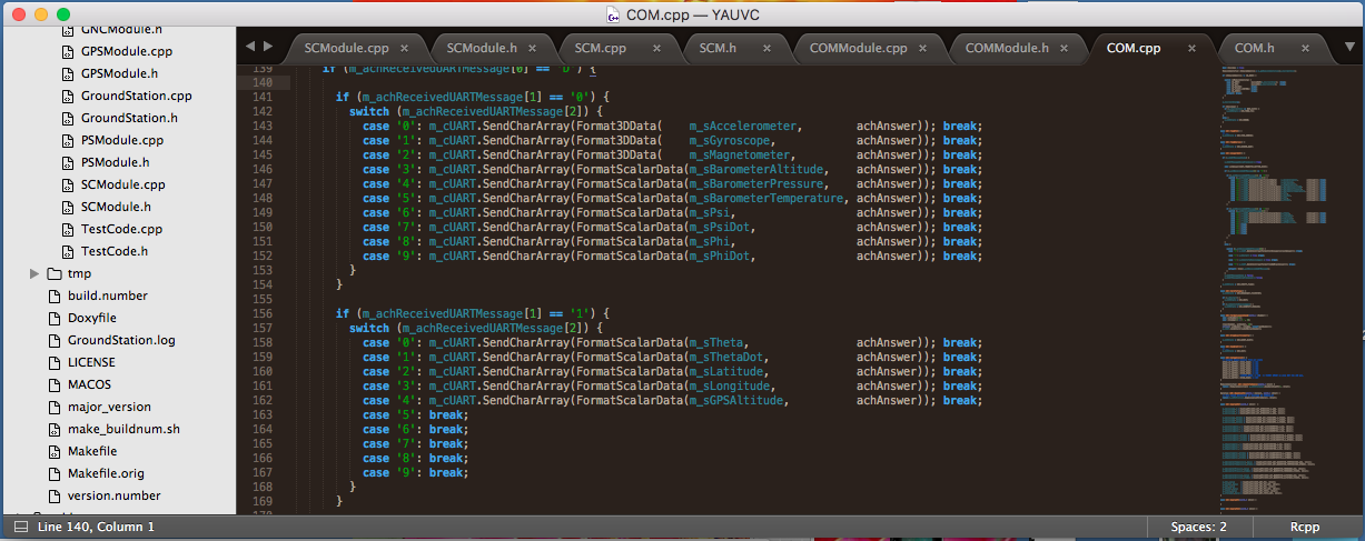
- I wanted full control of all the firmware code. Hidden code was also not an option. All the C++ code used in the system was (re)written and placed in open source classes.
To make all this work I had to develop and test some standards:
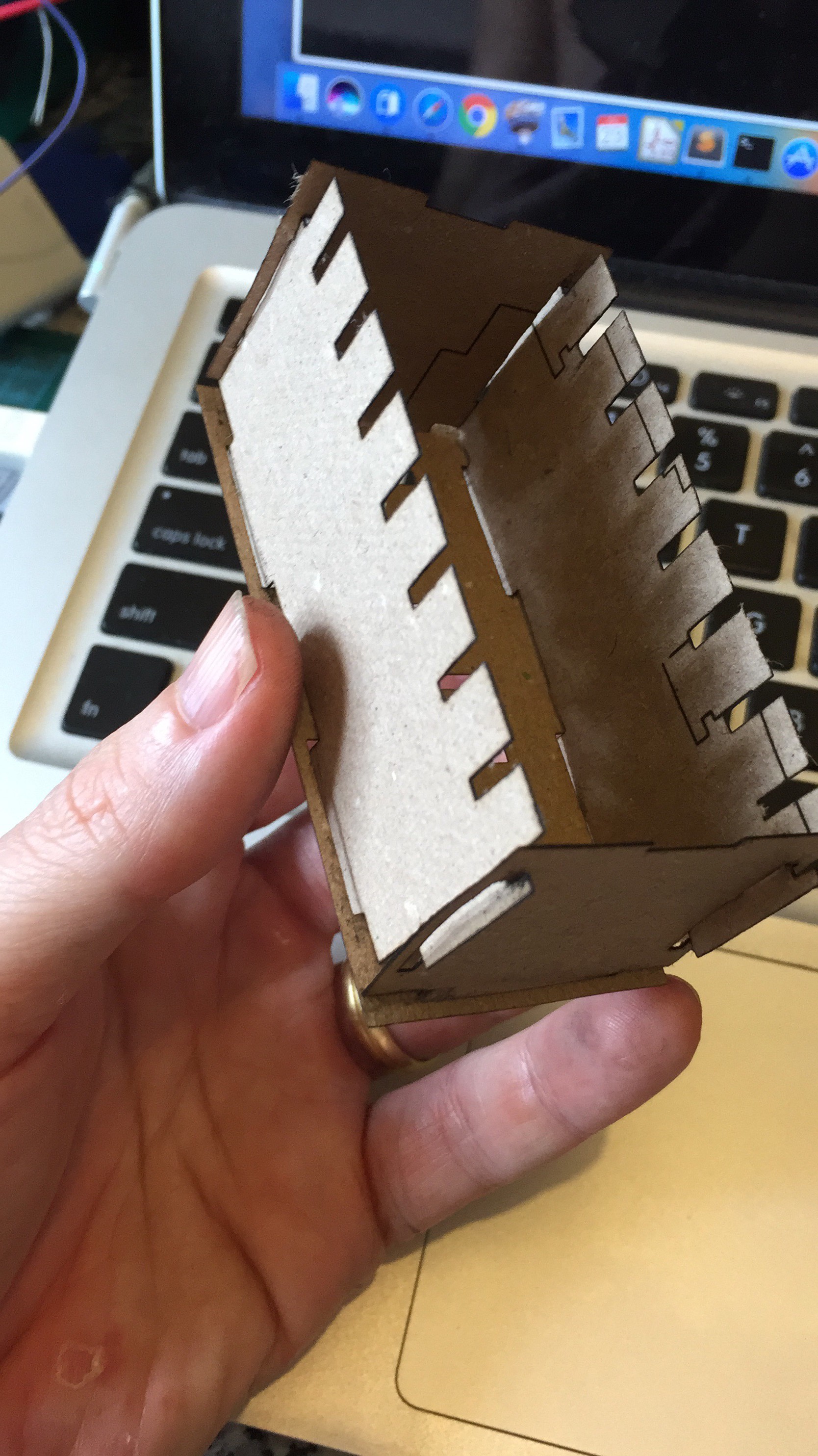
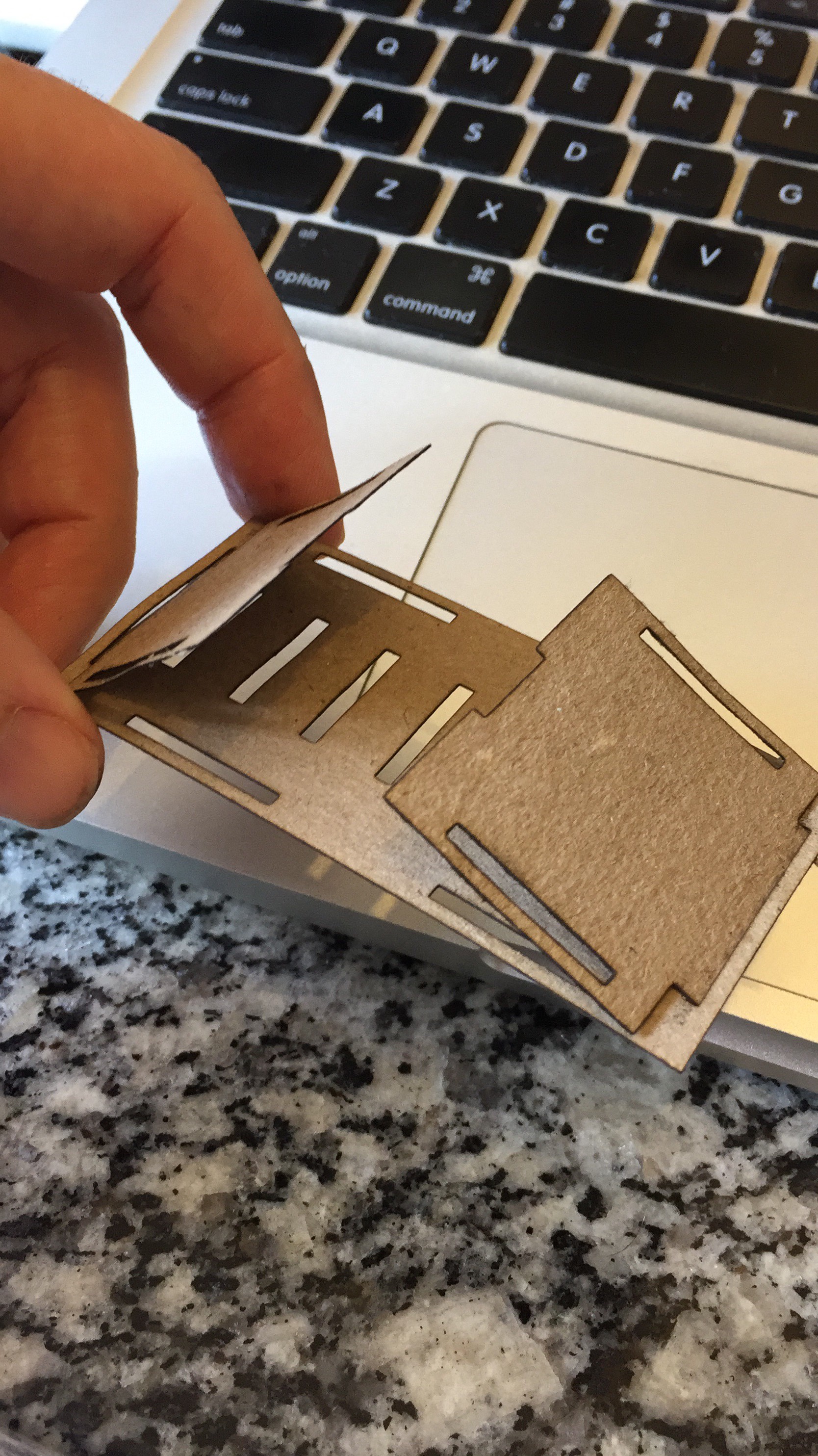
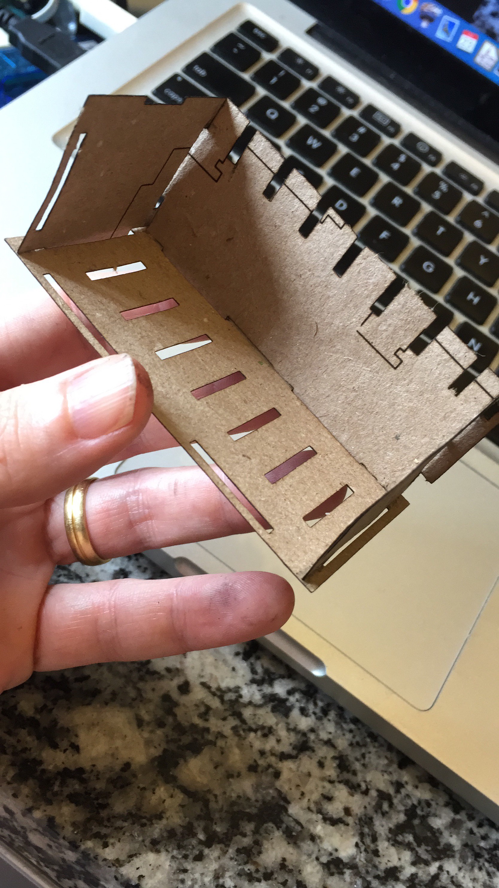
- The physical generic module size should be standard, be as small as possible, and should include a connection to the main bus and a connection to the submodule.
- The connection to the main bus should include power lines, communication lines and the possibility to reset a misbehaving module.
- The connection between a module and a submodule should have as many interfaces as possible, following a standard pin order.
- The submodule physical size should be as small as possible, but big enough to hold the necessary electronic components required for a vehicle control system, like sensors, GPSs etc.
- The communication between generic modules should be done using a simple, popular interface. I had to decide between SPI and I2C. The second one seemed to be the obvious pick, but after reading horror stories about locked I2C buses, I decided to use the SPI interface.
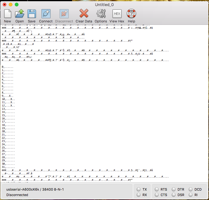
- As both interfaces transmit only a byte at a time, I needed a protocol to be able to transfer floats, longs or strings between modules. This protocol was written in C++ and is also a system standard.
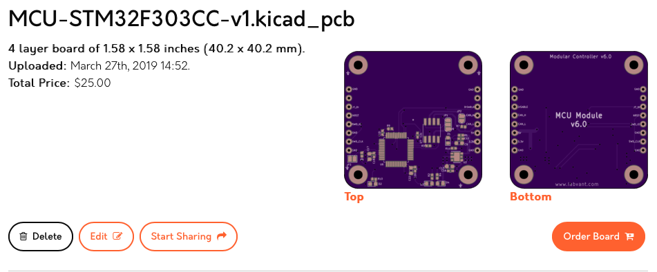
The electronic standards were translated to components in EDA software. In the beginning this software was Eagle, but after hitting its limits I decided to migrate everything to KiCAD. It took me some time to reach the current project status, which is partially described below, module by module.
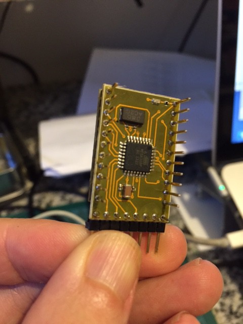
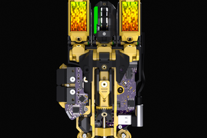
1 - MCU module: an ATMega328P in a little PCB, connected to the other modules by a main SPI bus. This module is surrounded by pads much like an Arduino stamp. These pads form a standard connection to a smaller module which I call a submodule. They deliver a second SPI, an I2C, a serial connection, two analog inputs and some GPIOs to the submodule. To enable the second SPI I had to remove the boot loader from the ATMega328P and strip all Arduino and wiring traces, rewriting what I needed from the beginning and redefining many things.
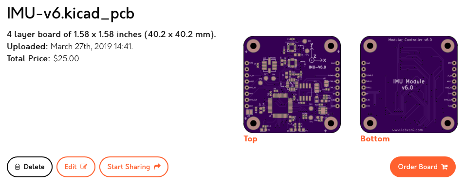
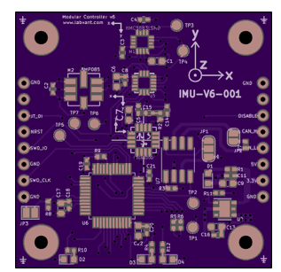
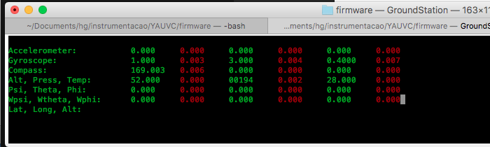
2 - AMGP sensor submodule: a small board that connects to the generic MCU module. This submodule has an accelerometer,...
Read more »

 benw
benw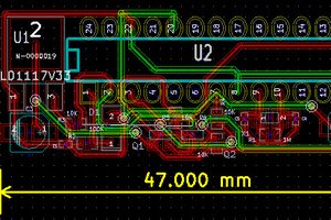
 Michael O'Toole
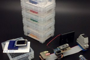
 William
Hi Mr Hering,can u share the code for Tricopter control ,i m in an urgent need