 Ted Yapo
I wind a lot of coils. Mostly, they're for RF use and either on toroids, or just simple free-standing air-core coils. I'm always careful to wind them neatly. When I started winding coils for testing magnetometers, however, I found I couldn't easily wind neat, layered coils on these particular spools by hand. @peter jansen solved this problem by building a nice coil winder. Being the impatient type, I took the other approach - scramble winding (aka jumble winding). We've all seen this done on on electric motors and other "electromagnet" components, and I even remember seeing some RF chokes from the vacuum tube era wound like this. What does this type of "random" winding do to the magnetic field? I decided to run some Monte Carlo simulations to find out.
Unfortunately, the tool I had at my disposal, the python loopfield package I wrote earlier, was painfully slow - each simulated coil took about two minutes to run on my laptop. If you've looked at the code, you know the dirty little secret - the first version was not vectorized. An evening of coding, and the newest version (on github and pipy) is vectorized over the field points, greatly speeding execution. Simulations on my laptop went from two minutes to about 1.6 seconds each (and a decent portion of that is for writing output images) - much better for doing thousands of Monte Carlo runs.
While I remember - the bug in matplotlib I stumbled into with the field-line plotting is known, fixed, and closed and will be rolled into the next point release. For now, the linked bug report has a better patch than my earlier suggestion.
Here's the model I used for scramble-wound coils. If you can think of a better one, let me know. I tried to capture the constraints that go into an actual coil:
The 100 turns are still organized into 10 rough "layers" - each of the 10 turns within a layer is assigned a nominal radius, then this value is perturbed by a uniform random floating point value between -5 and 5 winding spacings (the coil form is 10 "spacings" high). The idea is to capture the fact that turns may not have a well-defined radius, but constraints of winding the coil onto the spool still enforce an approximate layering. Similarly, in the axial direction, the turn position within the winding is perturbed uniformly between -5 and 5 row widths. These perturbations allow a loop nominally in the exact center of the winding to end up anywhere within the coil form. Since the coil really is in 3D, the off-axis tilt is moved into a random radial direction instead of remaining in the plane as the diagram might suggest. The center position (which may now be off the central axis) and the loop normal (which is generally no longer in the z-direction) are calculated from the nominal coil locations and offsets. This model assumes infinitely thin current loops, so there's no allowance for minimum spacing between windings - it's possible the model could place loops in exactly the same space (certainly closer than finite-diameter wire would allow). This perhaps isn't the best physical model for scramble-wound coils, but I think it's on the conservative/pessimistic side, and should at least give a qualitative feel for how the field uniformity is affected by "random" windings.
I ran 10,000 simulations of coils randomly generated in this way (using the numpy.random.random_sample() function, which I believe uses Mersenne Twister underneath). To analyze the results, I plotted the 1%-error contour area (relative to the two-loop reference coil) to a series of PNG images. Here are some representative images generated by the random sampler (the left image has the smallest area of the 10,000 samples, the right image has the largest, and the middle was arbitrarily chosen):

I think the left-most image is a pathological case; my simple model for random coils can easily generate non-physical arrangements of windings. Until I come up with a better model, I'll have to rely on a statistical approach.
I wrote a second python program that reads in all the images and estimates the spatial probability distribution for achieving the 1% bound. Since there is an equal chance of obtaining a mirror image of any coil on either axis, the images are flipped both ways during the accumulation, resulting in an equivalent 40,000 sample runs. Here's the estimate of the probability distribution:
Don't be confused by this plot - it simply shows the estimated probability of achieving less than 1% field error over the 2D area. It's difficult to distinguish the subtle reds in the central area, so here's a version thresholded at P(error < 1%) > 0.999, in other words, the area in which the field has a 99.9% chance of being within 1% of the reference field:
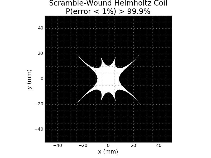
This region encloses a sphere of 16mm diameter compared to 25mm for the reference coil. Maybe a useful rule of thumb would be to de-rate the usable area dimensions for a scramble-wound coil by 40%. Then again, I think the random-winding model is conservative, as is the 99.9% threshold. It seems like if you can be a little more accurate in positioning within the coil, the errors introduced by scramble winding are easily overcome.
Discussions
Become a Hackaday.io Member
Create an account to leave a comment. Already have an account? Log In.
This is a really interesting analysis, and something that I've often considered (one of the reasons that I made the coil winder, and spend hours meticulously winding them!). This would seem to suggest that haphazard windings may not have a very large effect on field intensity, for many applications. But, I wonder, does having windings in so many different directions affect the orientation of the field? The magnitude of the vectors seem to be stable over a fairly large region, but does their direction have a large amount of wobble to them? (Which would be important for, say, an Earth's field MRI :) ).
Are you sure? yes | no
I thought about the direction issue a little as well. When I did my first analysis of the fields, I decided to use only the x-axis (labeled "z" in some places :-) component of the field as a figure-of-merit. So, the 1% error bound represents the area in which the x-axis component is within 1% of the reference coil (ignoring the other two components entirely). For magnetometer calibration, where the cross-axis sensitivities are known to be small (the MLX90393 datasheet quotes 1%), I figured this was a good metric. I've subsequently used this same metric for all the analyses, including this one.
I think using just the x-component does capture some of the directionality of the field. What this analysis fails to capture is if there are additional components in the other two directions, which would influence the direction of the vector field. I can wave my hands and say that there's only so much magnetizing current, so these other components must be relatively small (and hence the direction fairly uniform) if the x-axis component is decently uniform, but it's not a very satisfying argument.
I guess you could come up with a better way to capture the "direction wobble." I think if you normalized the field at each point, then took the x-axis component, you'd have a better direction metric. This is equivalent to the dot product between the i-vector and the normalized field, which is just the cosine of the off-axis angle. You could take the inverse cosine if you wanted the results in degrees (or radians) - an explicit measure of the wobble. Maybe I'll kick off another Monte Carlo run today; I think it's a one-line change for the metric (and then a bunch for the thresholds and labeling the plots), but the computer will do the hard work :-)
Maybe the best representation of the results would logically combine two thresholds, e.g. (magnitude within 1%) and (direction within 1 degree).
Don't get me wrong on the whole issue, though. I'd rather have a a neatly-wound layered coil and not worry about it. The amount of energy I'll spend to justify my own laziness is baffling.
I'm going to have to read up on exactly what you're doing over there; my MRI knowledge is limited to having been through the reconstruction math a while back. My memory of it is fairly low-resolution...
Are you sure? yes | no