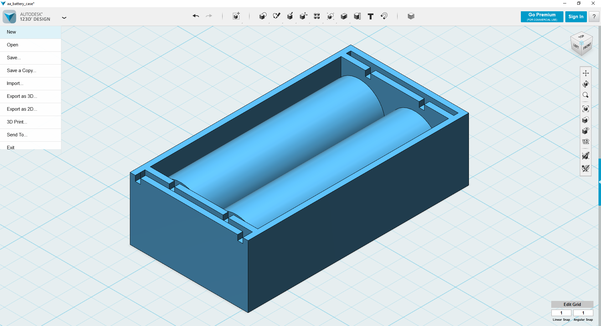
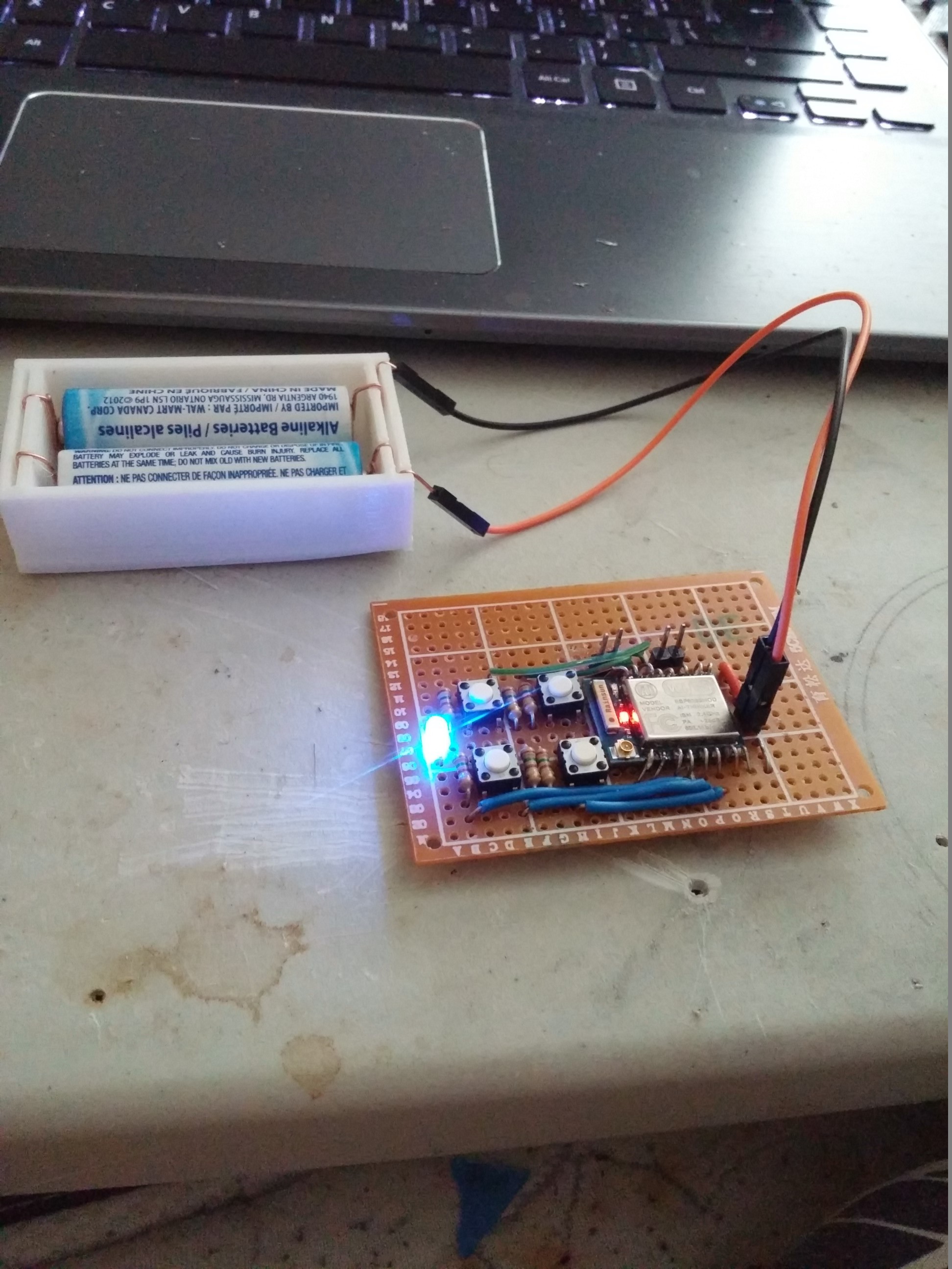
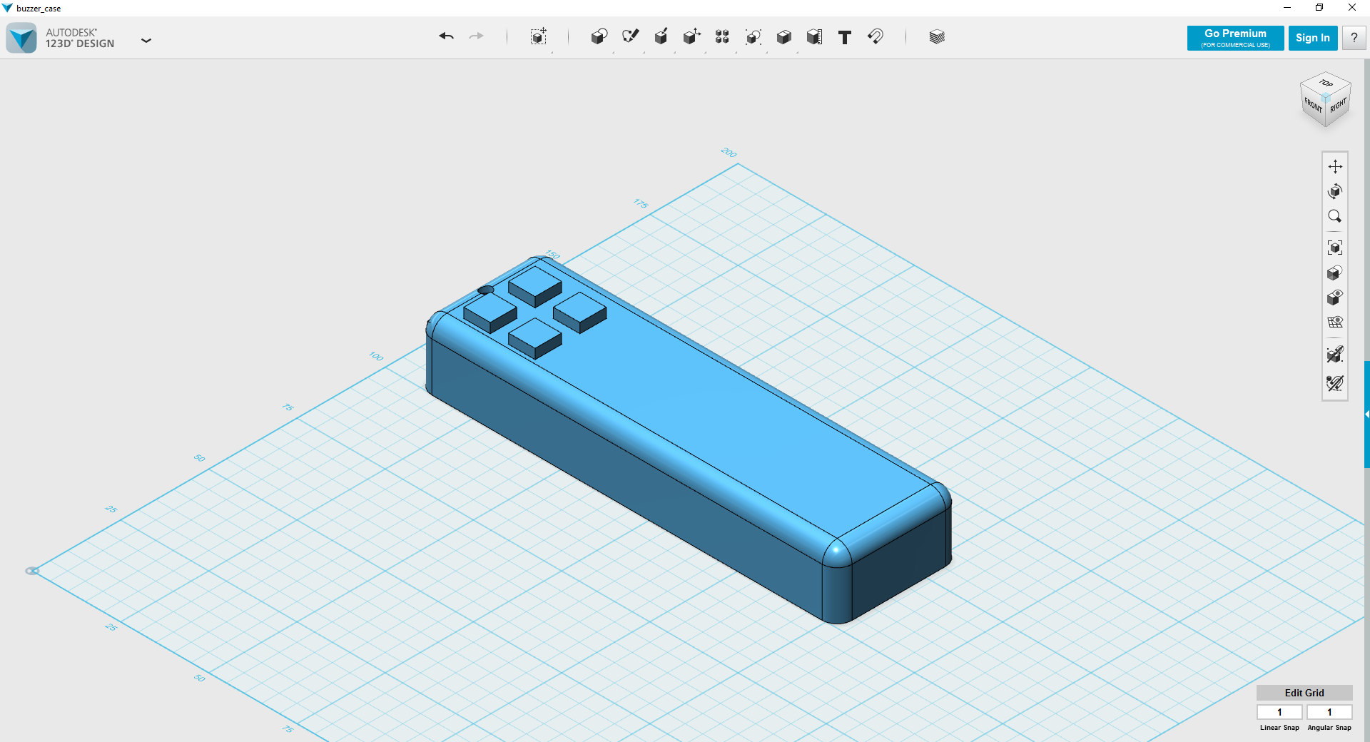
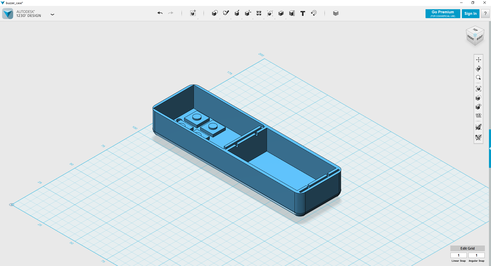
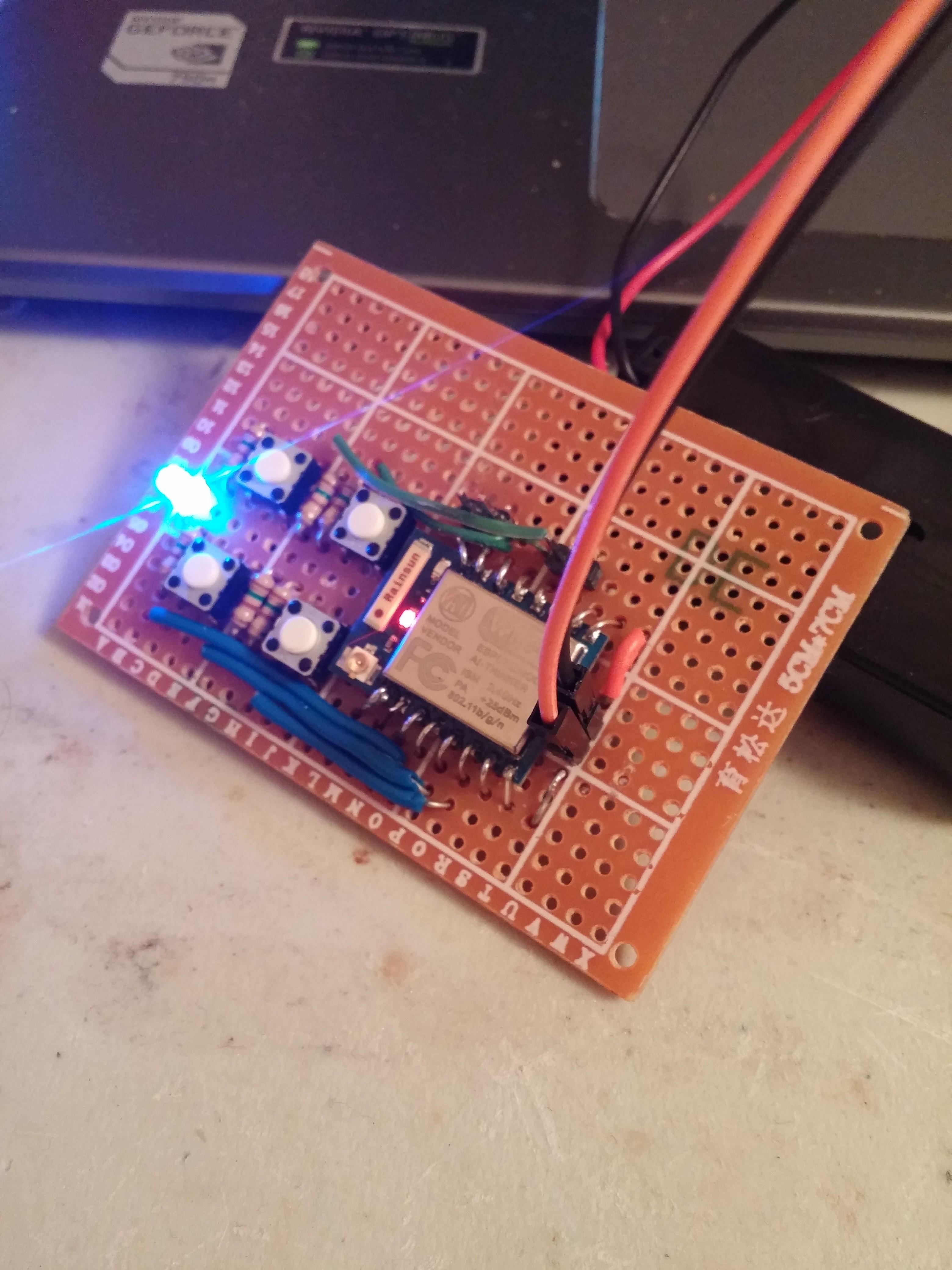
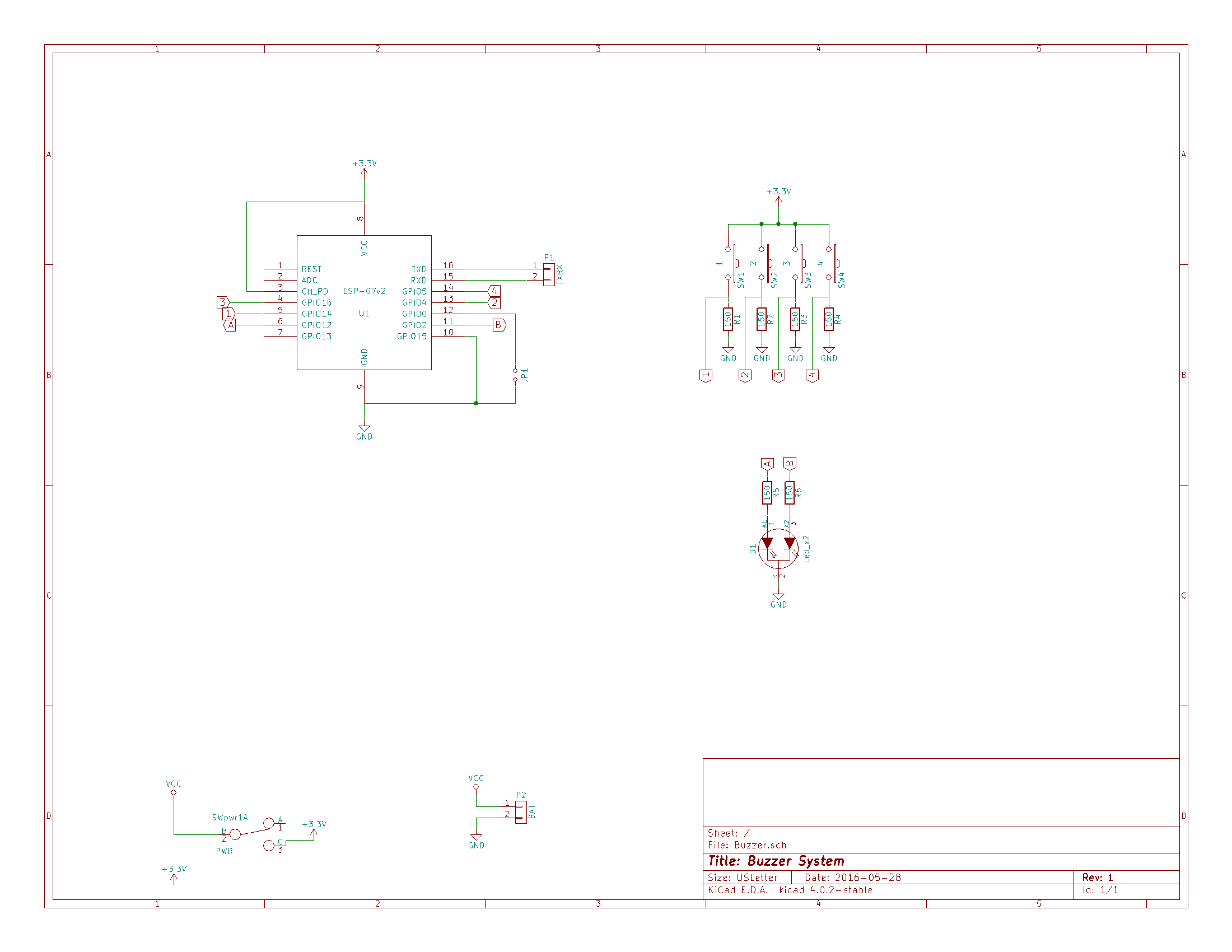
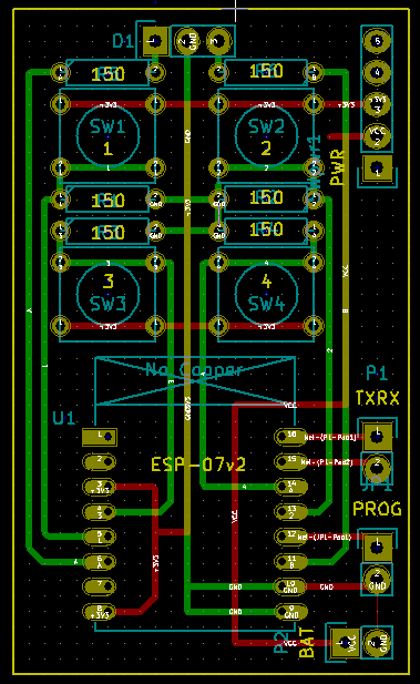
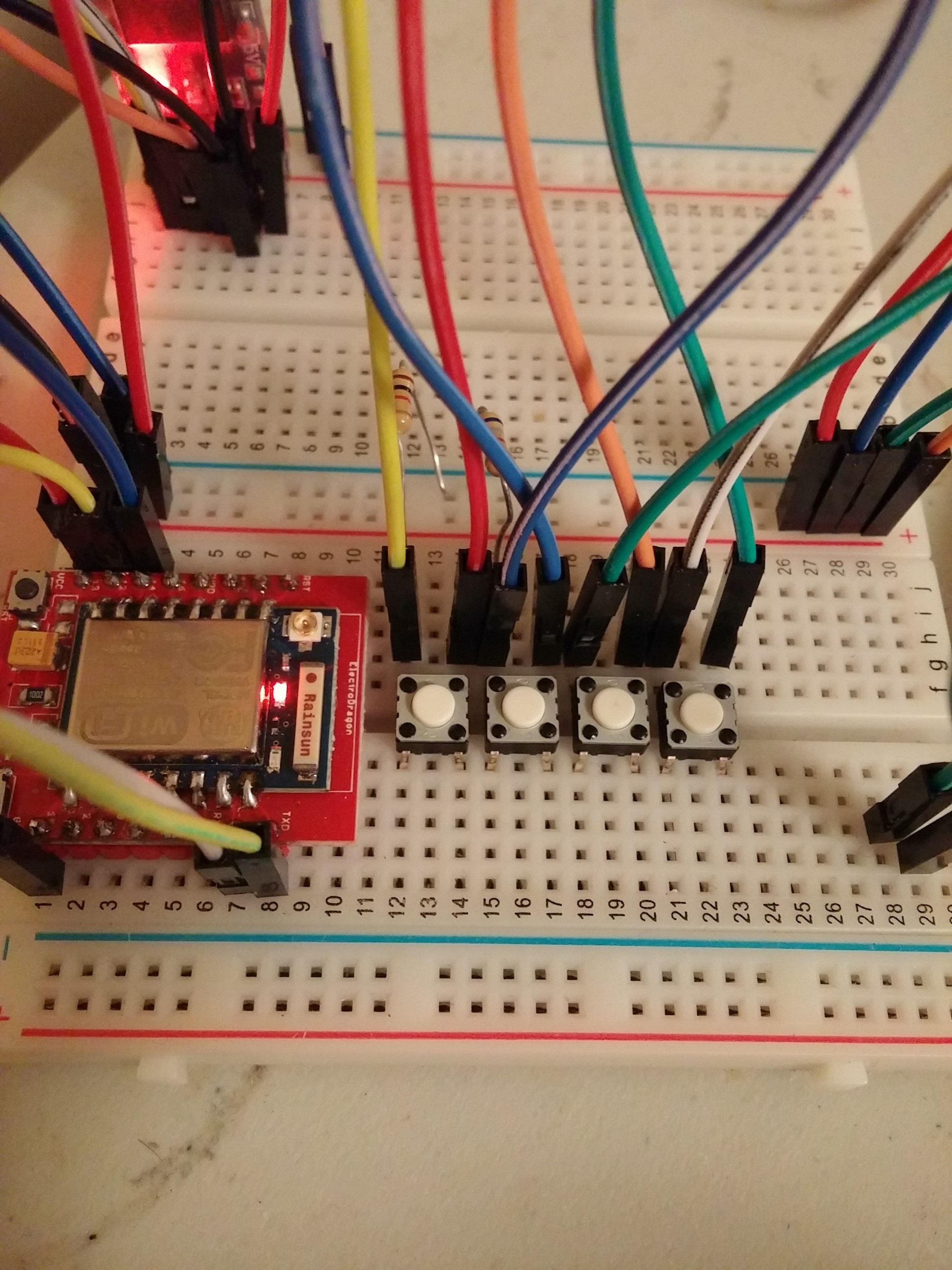
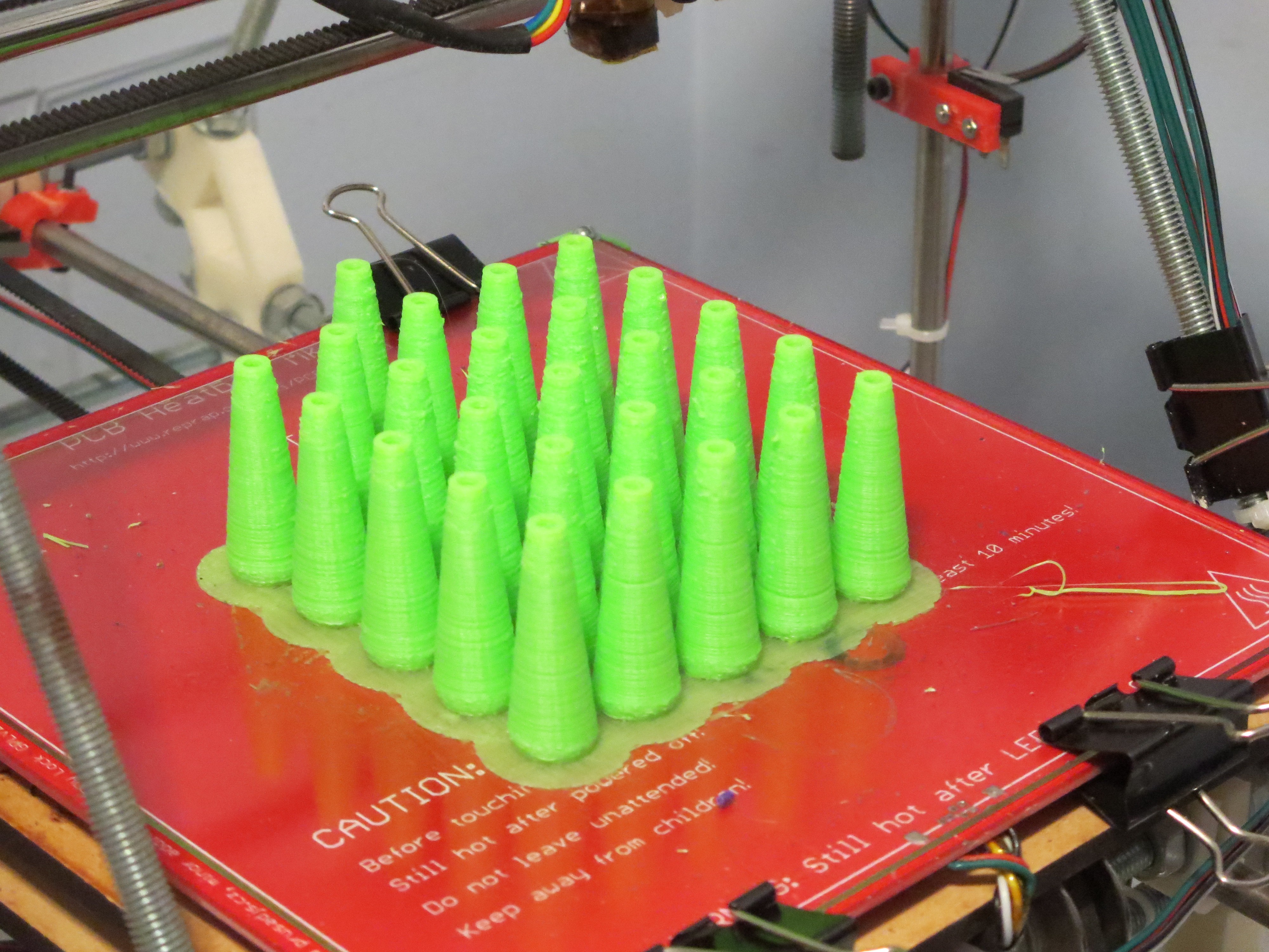
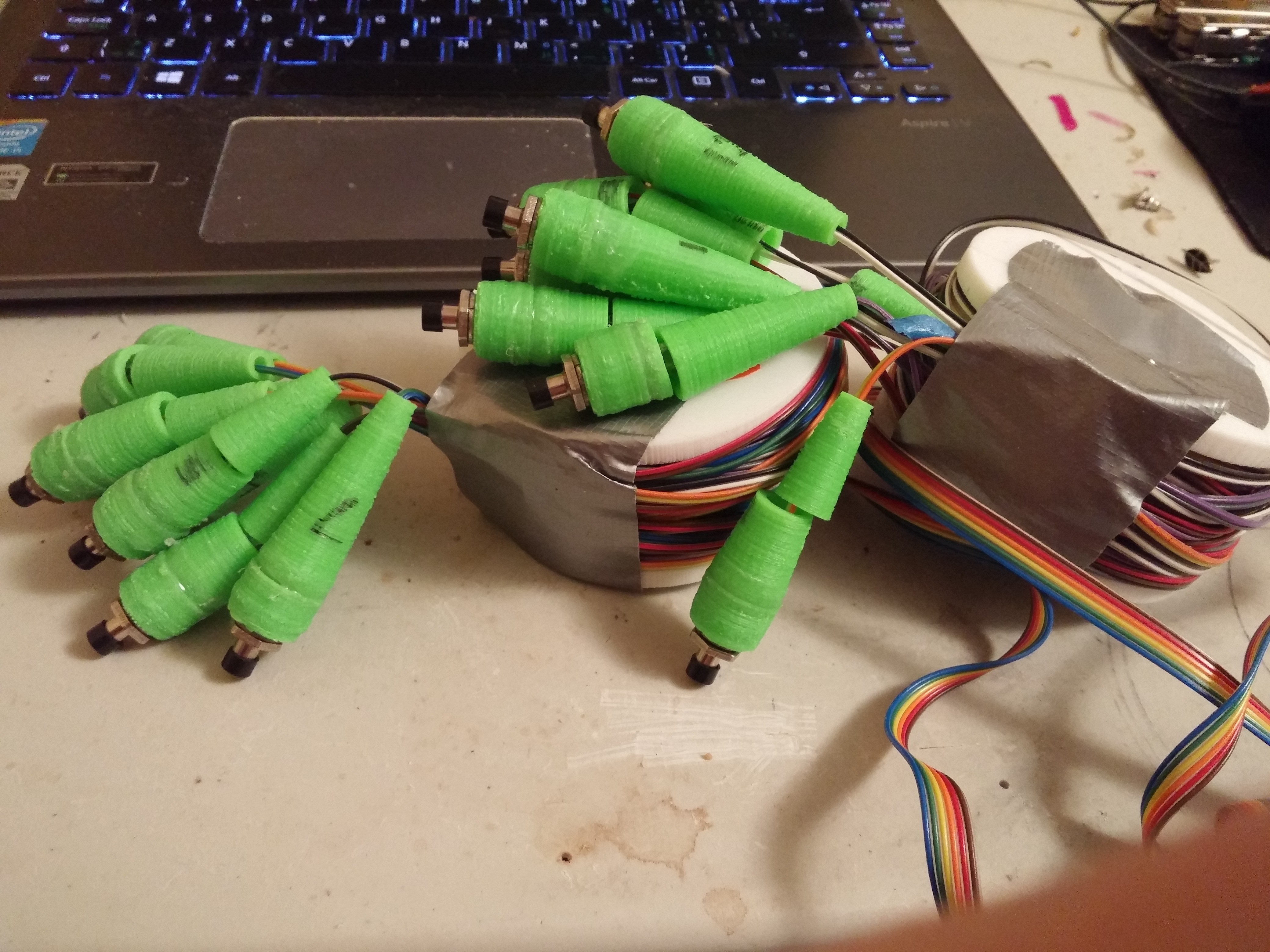
• a case for the future

    K Gilbert05/29/2016 at 21:50 2 comments

    Today design turned poligonal with thoughts of case working floating in my head first concern was power, looking through the usual retailers i found that battery trays would increase the size and price beyond what i was comfortable with, I then looked at just the metal clips that hold batteries in place, they too are too expensive. Early this morning i was thinking and i saw a roll of very stiff wire on my desk and thought i could use that to make springs. so i quickly drafted up a case to hold a design and printed it off to test. You can see below the rigid 0.8 mm wire can fit into the groove and can be bent in usual battery clip shapes.

    Here it is in person.

    So from here I morphed out this design to fit in the circuit and buttons and lights. Since i'd like to have the circuit boards in my hands first before putting too much work into this, these are more of mock ups than revision ones.

  • Ready, fire, aim

    K Gilbert05/29/2016 at 02:27 0 comments

    This morning with my proof of concept breadboard design I decided to mock up a compact version. This was good for visualizing how big the final product the circuit board is about the size of a pair of AA batteries which just so happens to be what will be providing power to it. Going through this processed reminded me i don't want to hand wire 24 of these. So i spent the rest of the evening drafting up a circuit board.

    I've been learning kicad recently and have decided to give it a go by myself, the quite simple fruits of my labour is listed below. Not much to document besides the result itself.

    From here I created a pcb, with these parts. Once again not much to say, I did it dual layer, and prepared it to be fabricated at OSH park. Since i've never done i'm pretty sure there must be an error, but i decided to send it out before overthinking it, i'll find out in a few weeks if I wasted 13 dollars.

    Not many words to say, but super excited about the progress I made today. Tomorrow i'll better document the software and get started looking at case designs.

  • the proof of concept

    K Gilbert05/28/2016 at 05:14 0 comments

    Simple update from my work last night to get a the switches up and running. I harvested the switches from the io board of a printer I recently disassembled, wired up the board, tested getting a read from the board.

    From there via the serial monitor I was able to see the buttons were reading ok. from here I configured it to connect to an ad hoc wifi network and send udp packets at the gateway ip.

    On the server side I setup a simple echo UDP server, which displays which button is pressed, which i had up and and running by the end of the evening. some error handling and receive confirmation still needs to be done but it's a test bed to work from.

    This leaves the next step to get a more permanent perfboard version, and rig it up into a 3d printed case. From there I can consider the feasibility of using custom pcb for the production version.

  • the precursor device

    K Gilbert05/28/2016 at 03:46 0 comments

    When I first started this project a years ago I started with simple idea, I originally designed cases for switches and had wires connecting to shift registers that directly interfaced with a raspberry pi which displayed the number of the first user to press the button after the presenter pressed their button. This system was a mess of wires, which made it figuratively impossible to detangle.

    Some images of the original design. first is the cases directly off the printer,

    bottom of case, to be hot glued into top with wire running through hole.

    Top of case

    Next is the switches being fitted into the tops of the case, a wire is threaded through each of the bottom cases. A knot is then tied for stress relief, the cable is soldered to the switch, and the case is hot glued together, i only took photos of the first step.

    Switches inserted into top of cases

    Then the shift register board wired to the Pi

    Because of the obvious flaw of cable management a revision was made intending to be debuted at this year's trivia event, this time I broke the switched down to groups of eight each directly connected to their shift register, the shift register was stored in their respective spool and wired together via removable cabling, the theory being that it was easy to separate the groups and untangling 8 is infinitely easier than the full 24. Unfortunately although it was completed in time for the event this year there were some shorts/bugs in it that made us forgo its use.

    We are now 11 months away from the next time we will need it, best time to throw it out completely.