 will.stevens
The video below shows relays with copper contacts being used to make a divide by 3 circuit. This is much more successful than my earlier attempt to make the same circuit (part of project log dated 10th Oct 2016). The copper contact relays operate from a lower voltage than my earlier relays, partly because I've become better at assembling them, partly because the new relays only require one nail per contact, whereas previously I had to double-up to compensate for the unreliability of the nail-nail contacts.
Below is the circuit diagram, repeated from the 10th Oct 2016 log entry:
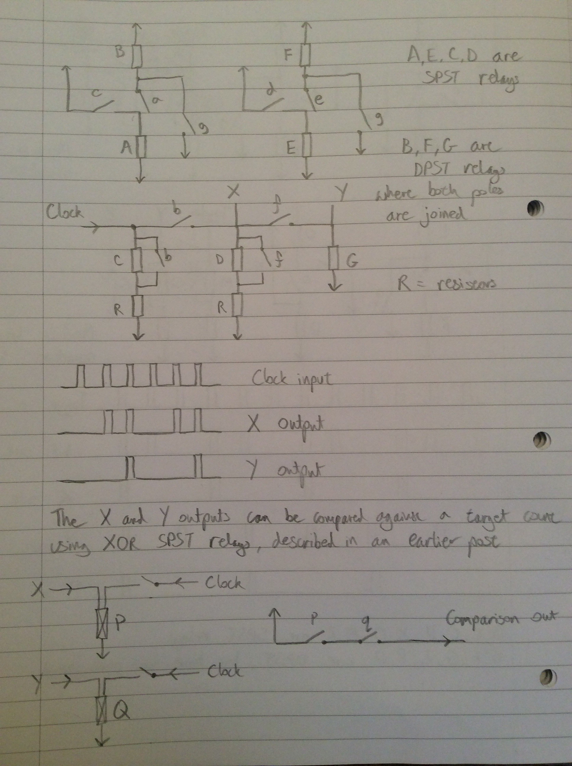
Relays (A,B) behave like a trailing-edge driven set/reset circuit, where C provided the set signal and G provides the reset signal. The contacts of B change state immediately after removal of the set or reset pulse. Relays (E,F) are a similar circuit. The network of relays and resistors involving relays C,D and G route the clock signal to the appropriate place depending on the state of relays B and F.
E.g. If neither B nor F are active, the clock signal is routed to set (A,B). If B is active but F isn't then the clock is routed to set (E,F). If both B and F are active then the clock is routed to reset both.
Below is a video of the same circuit stepping a motor on every third clock pulse:
Discussions
Become a Hackaday.io Member
Create an account to leave a comment. Already have an account? Log In.
I still don't understand the diagrams but I'm still impressed :-)
Are you sure? yes | no