 Yiğit Topcu
Challenge
There are many products available as Smart Lock on the market, few of them looks great and affordable but none of them are compatible with the European BS EN 1303: 2005 cylinder locks.
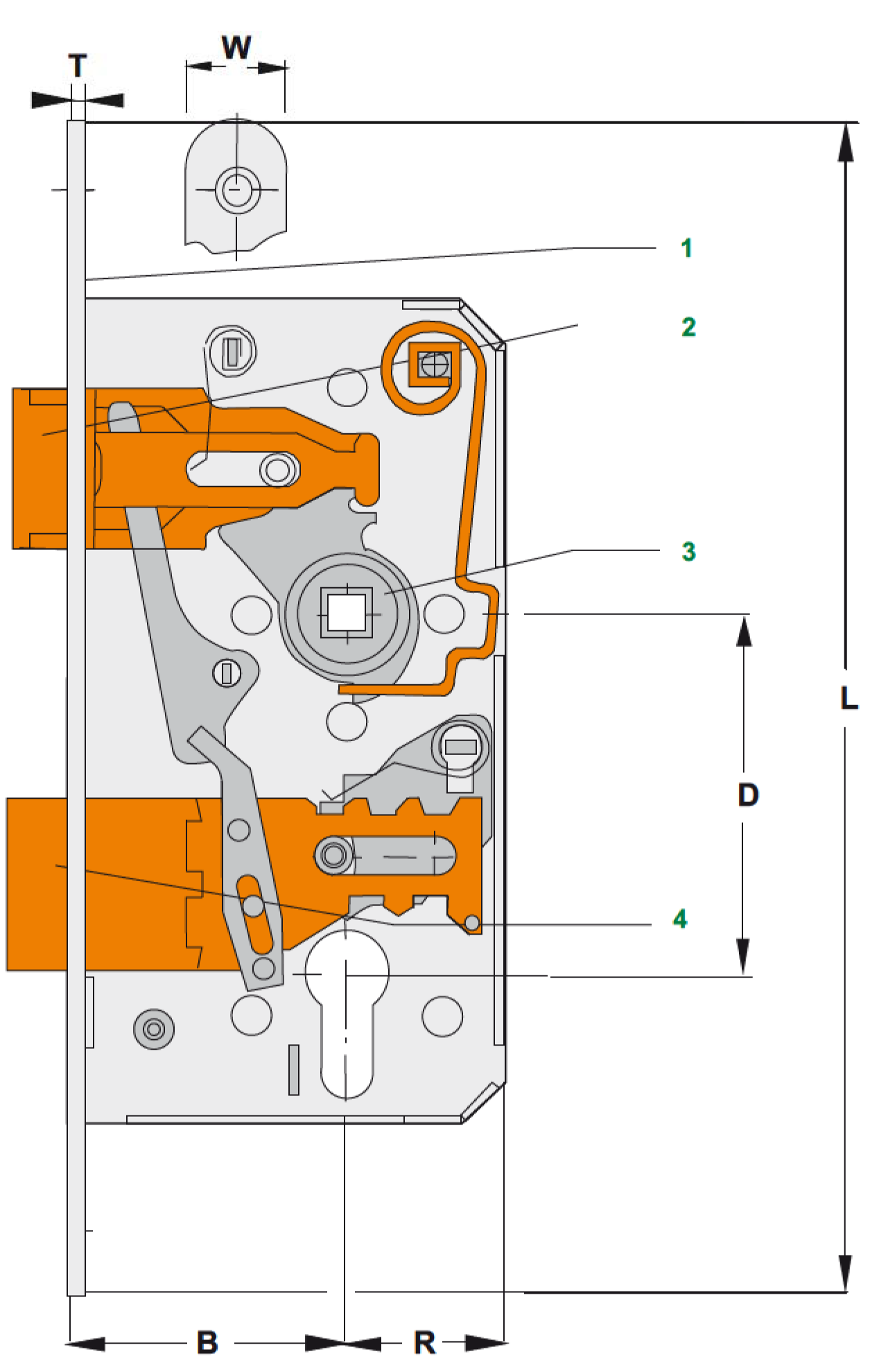
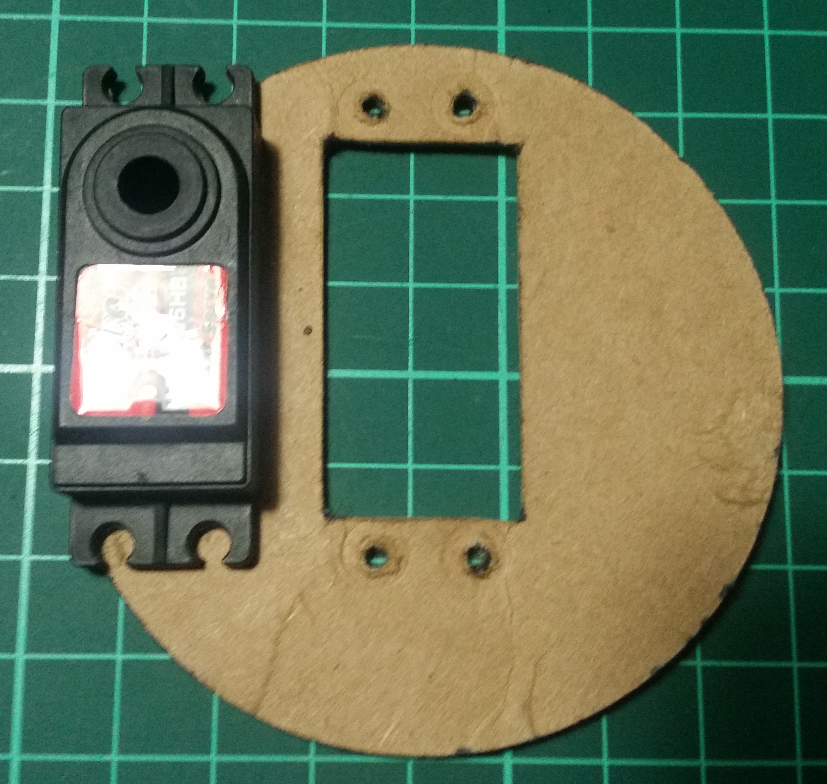
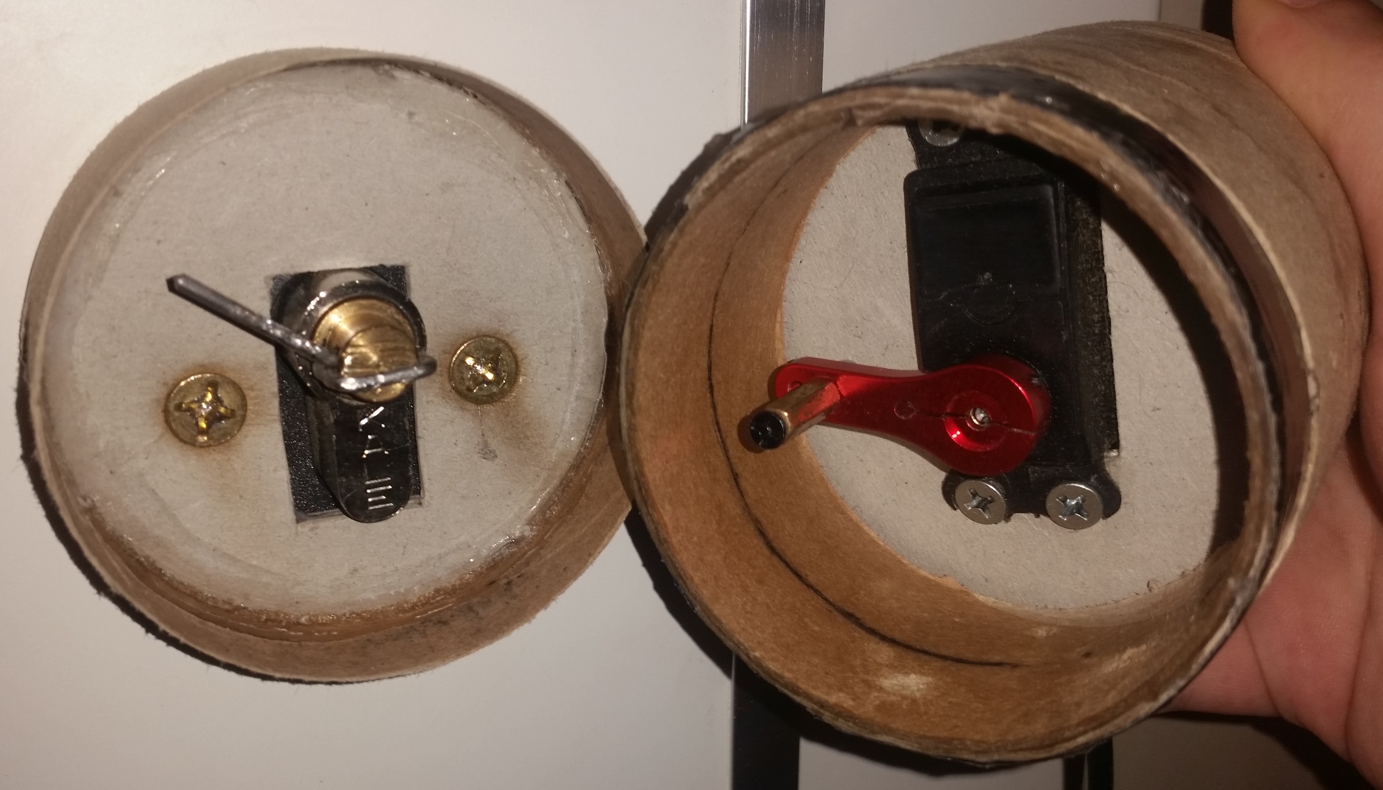
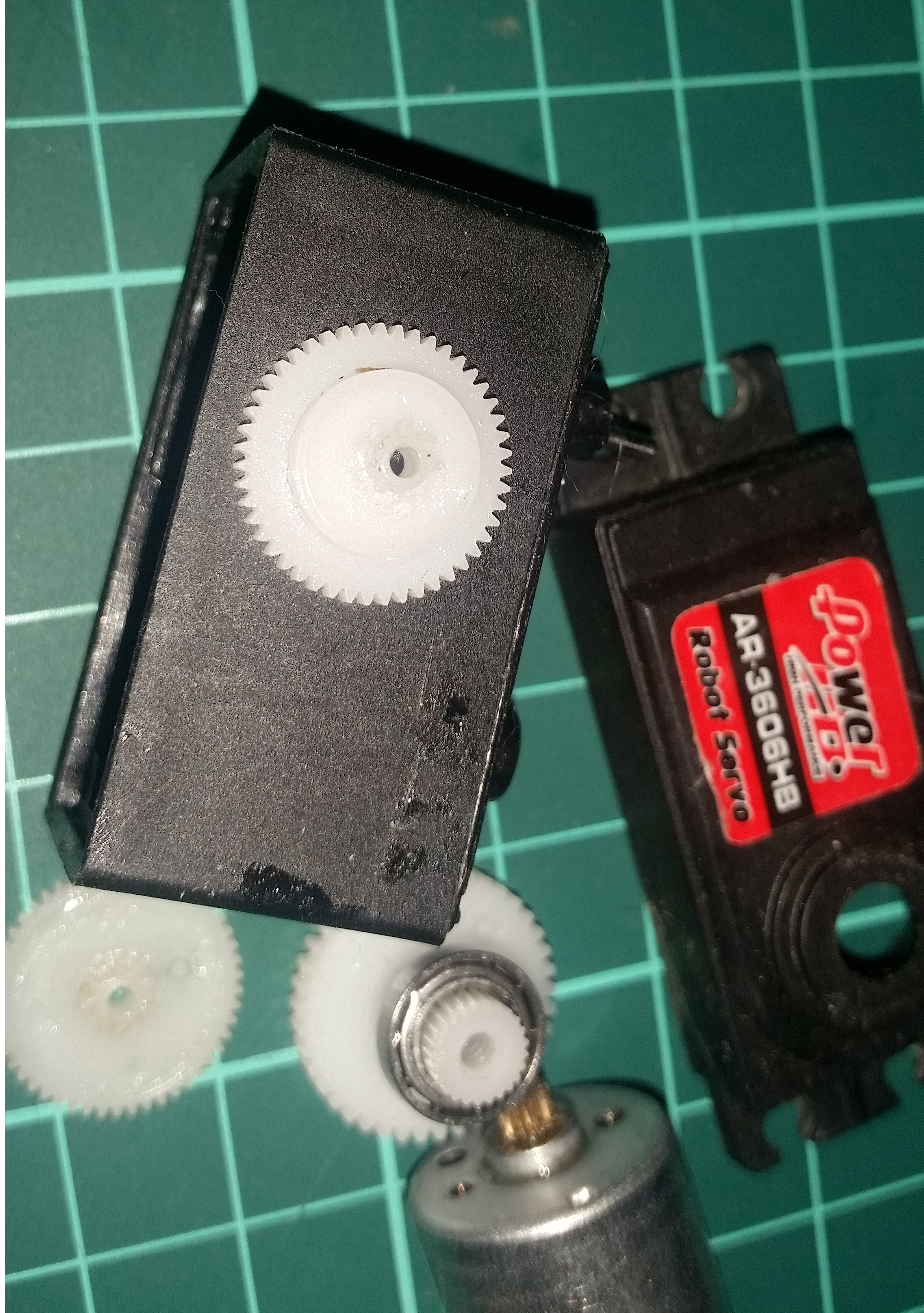
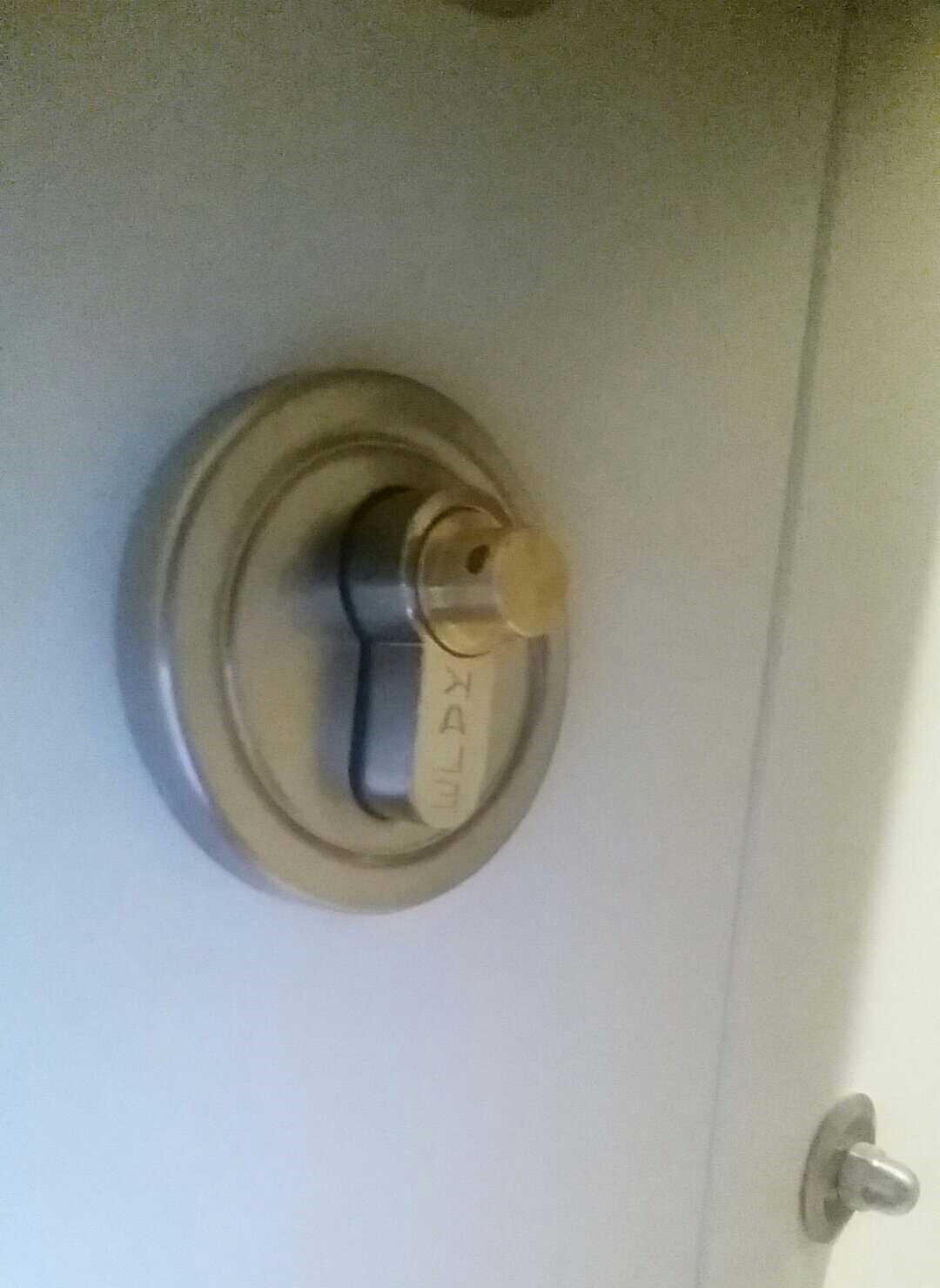
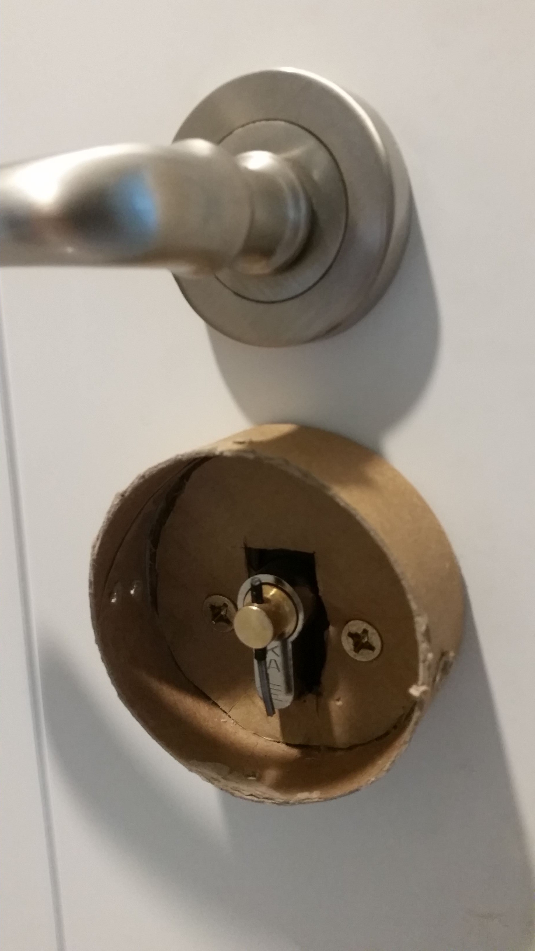
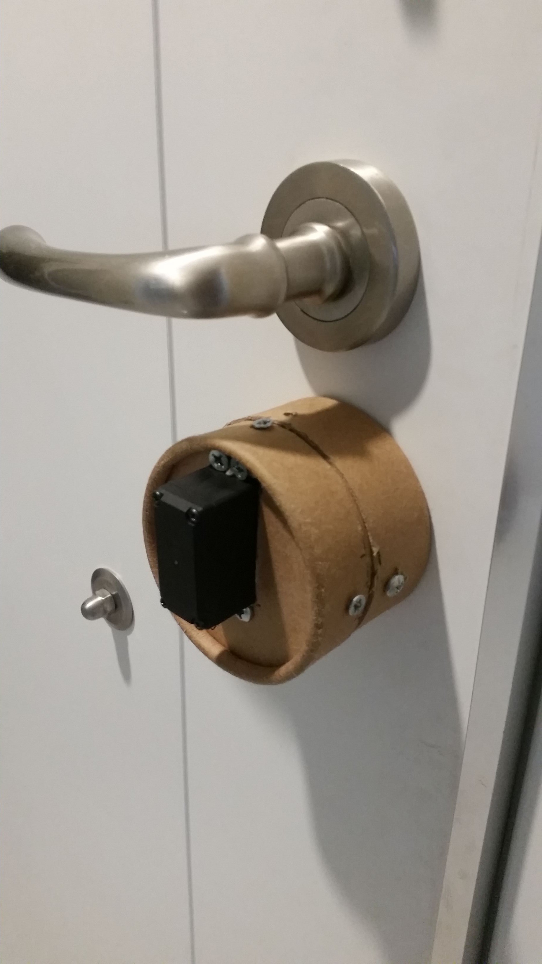
Europe door lock standards are different compared to the door lock standard of North America. Basically there is no door handle outside of the door. From the outside, the door can only be opened by using the key. Therefore, European doors have a single lock cylinder that is used to lock and open the door. Because of that, the mechanism I've built has to be completing three full turns from side to side. And also cylinder needs enough torque because of the internal mechanics and springs of the lock itself.
Objectives
- Device must be cheap. This means no expensive motors or sensors can be used.
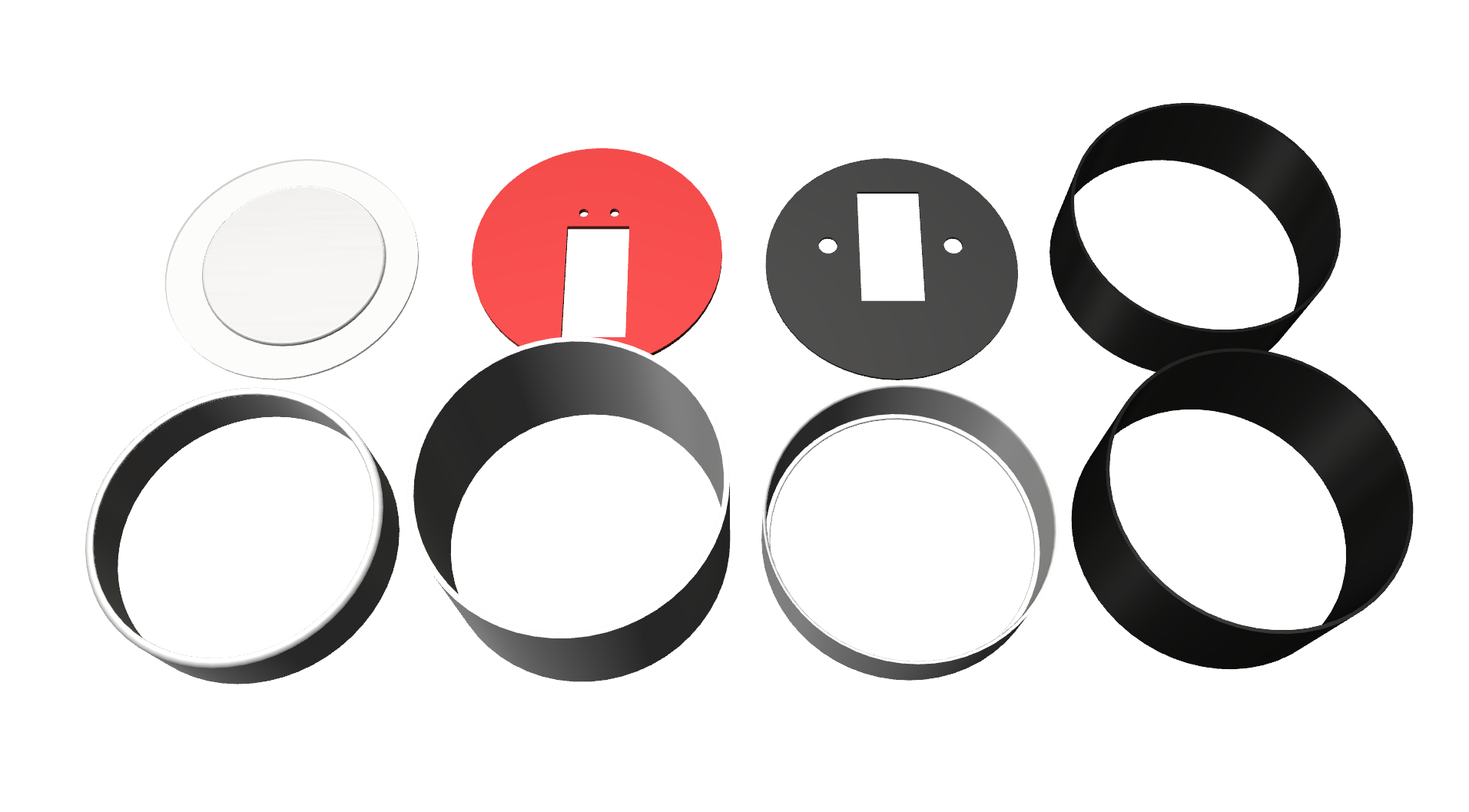
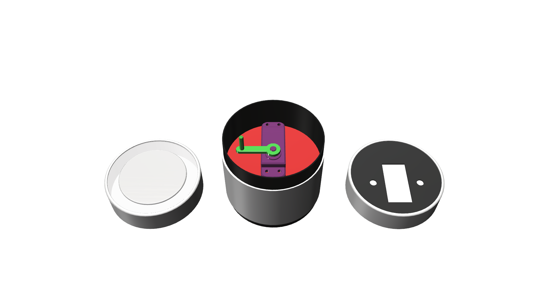
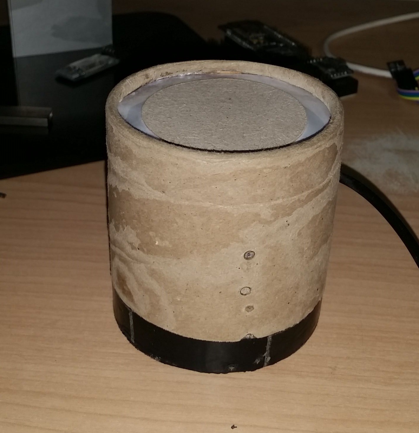
- Device must be presentable. I don't want to see any cables, electronics not even the motor itself on my apartment door (since it is a very small apartment).
- No modifications on door itself. I am a tenant at this apartment right now so I can't modify anything that can't be fixed.
- It should be secure. Most of the RF devices are vulnerable to replay attacks, the lock should be safe enough.
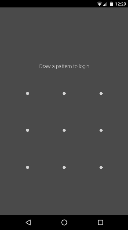
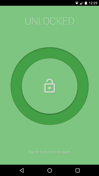
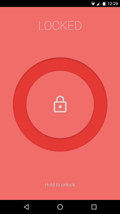
Concept
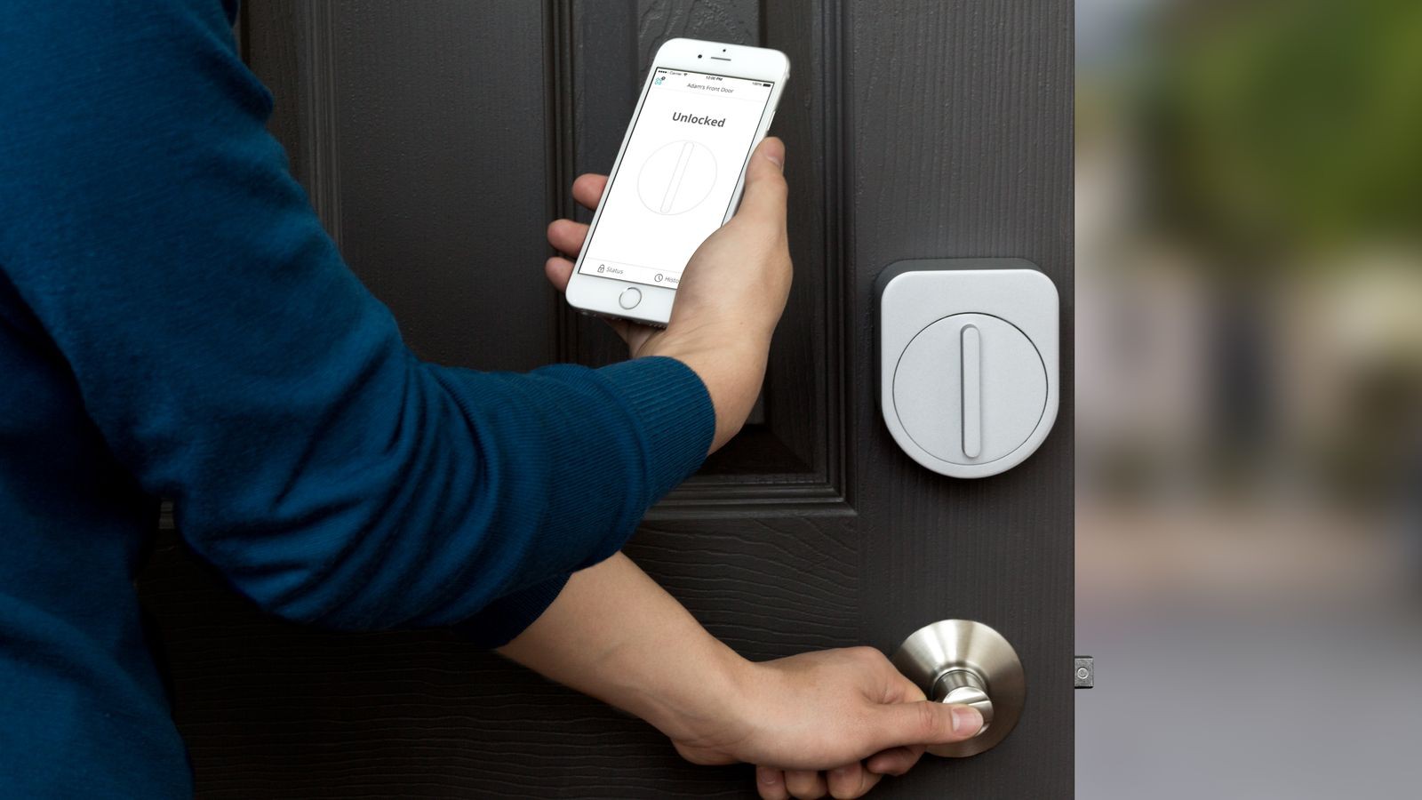
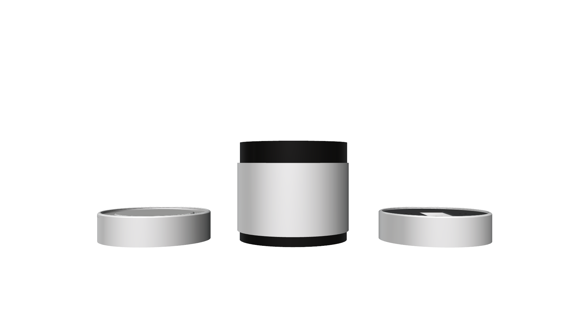
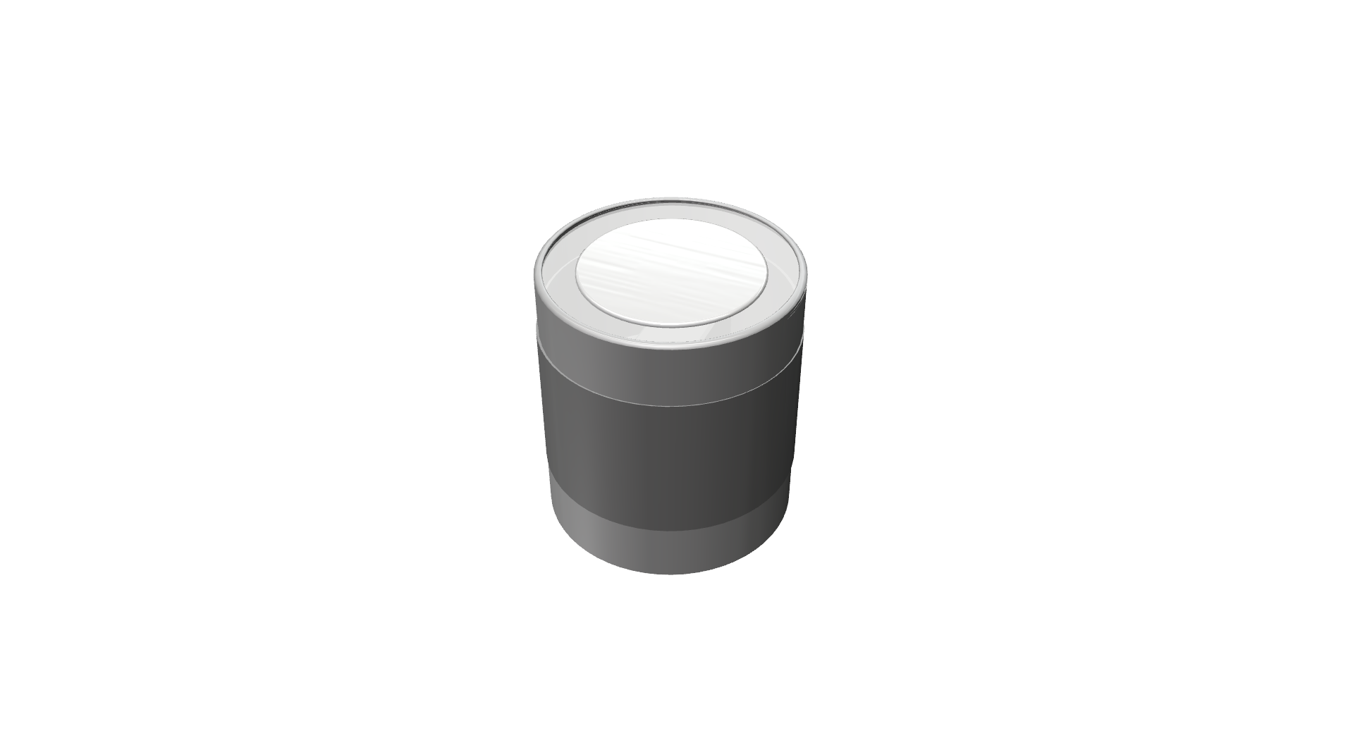
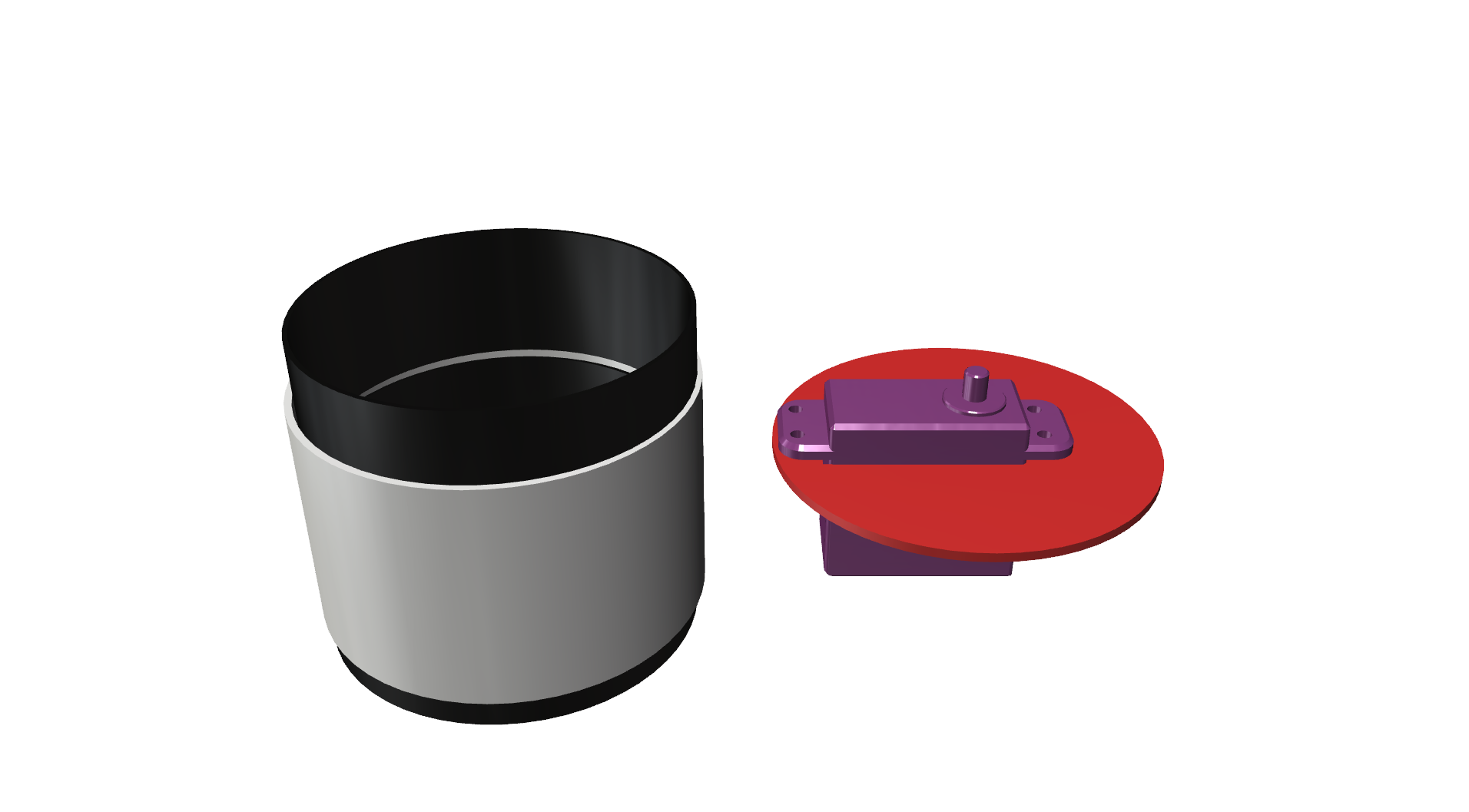
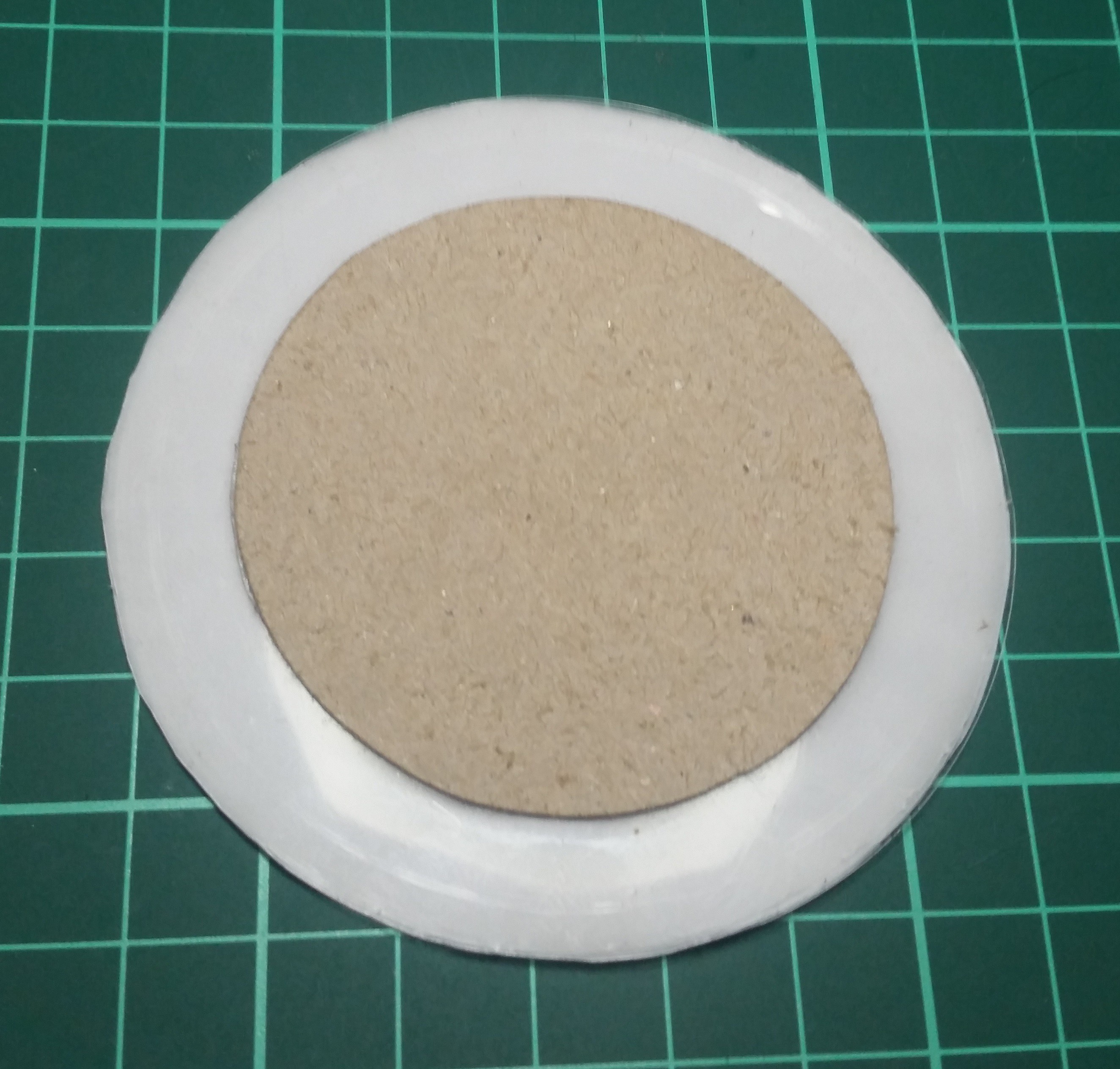
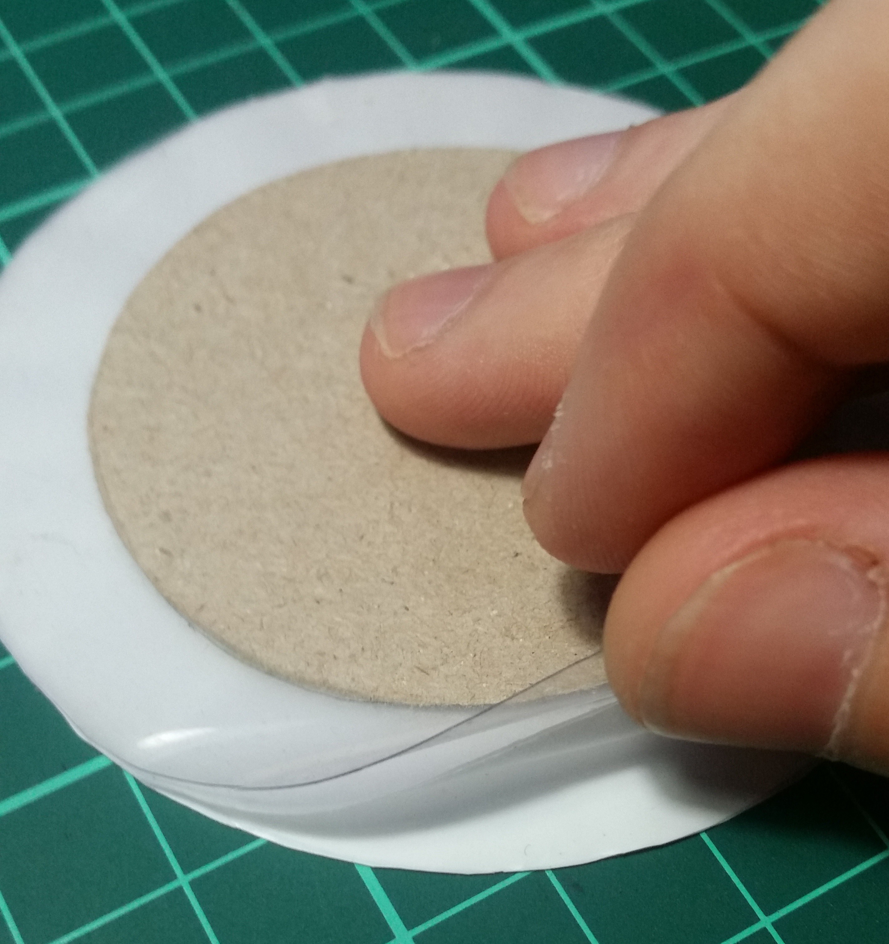
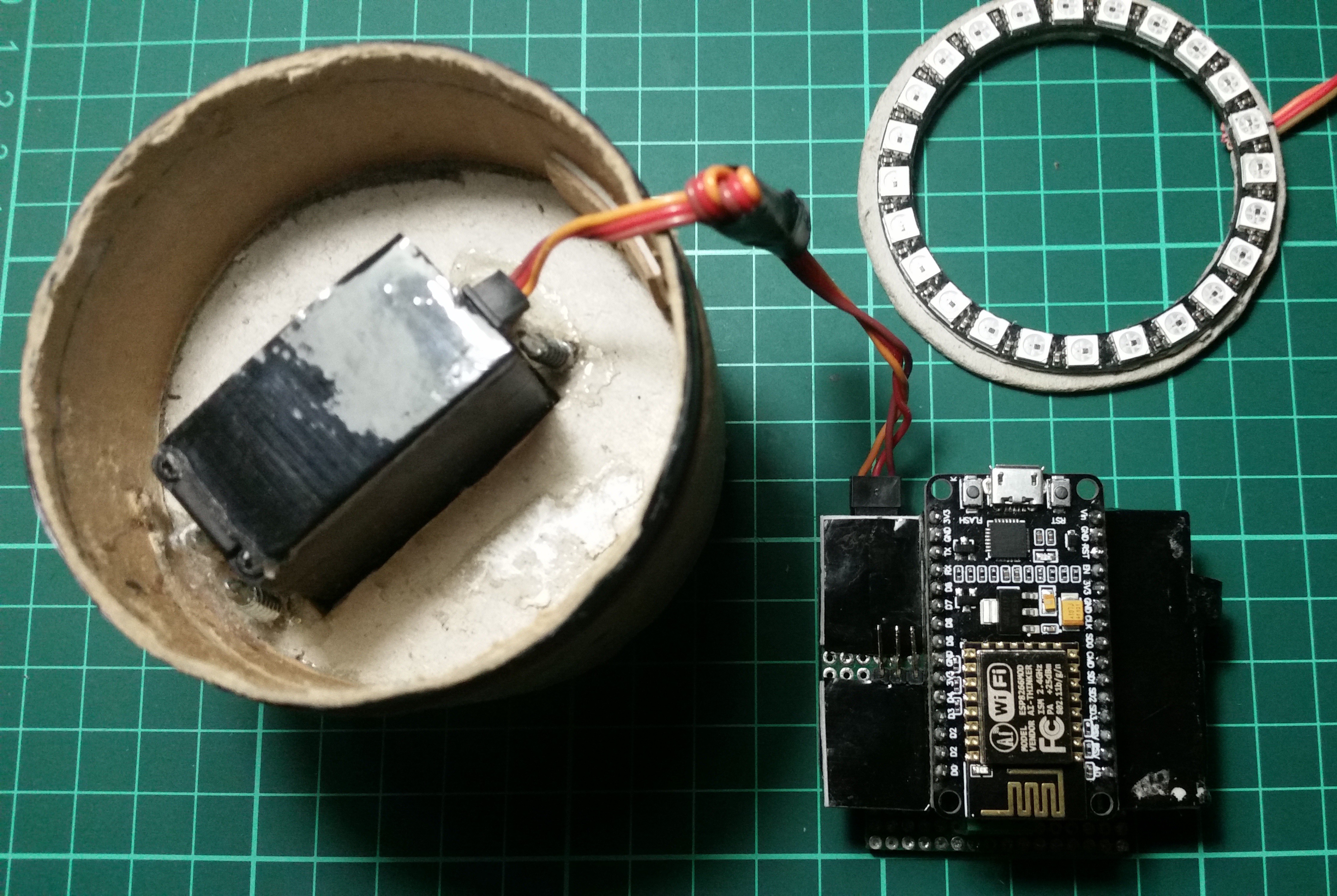
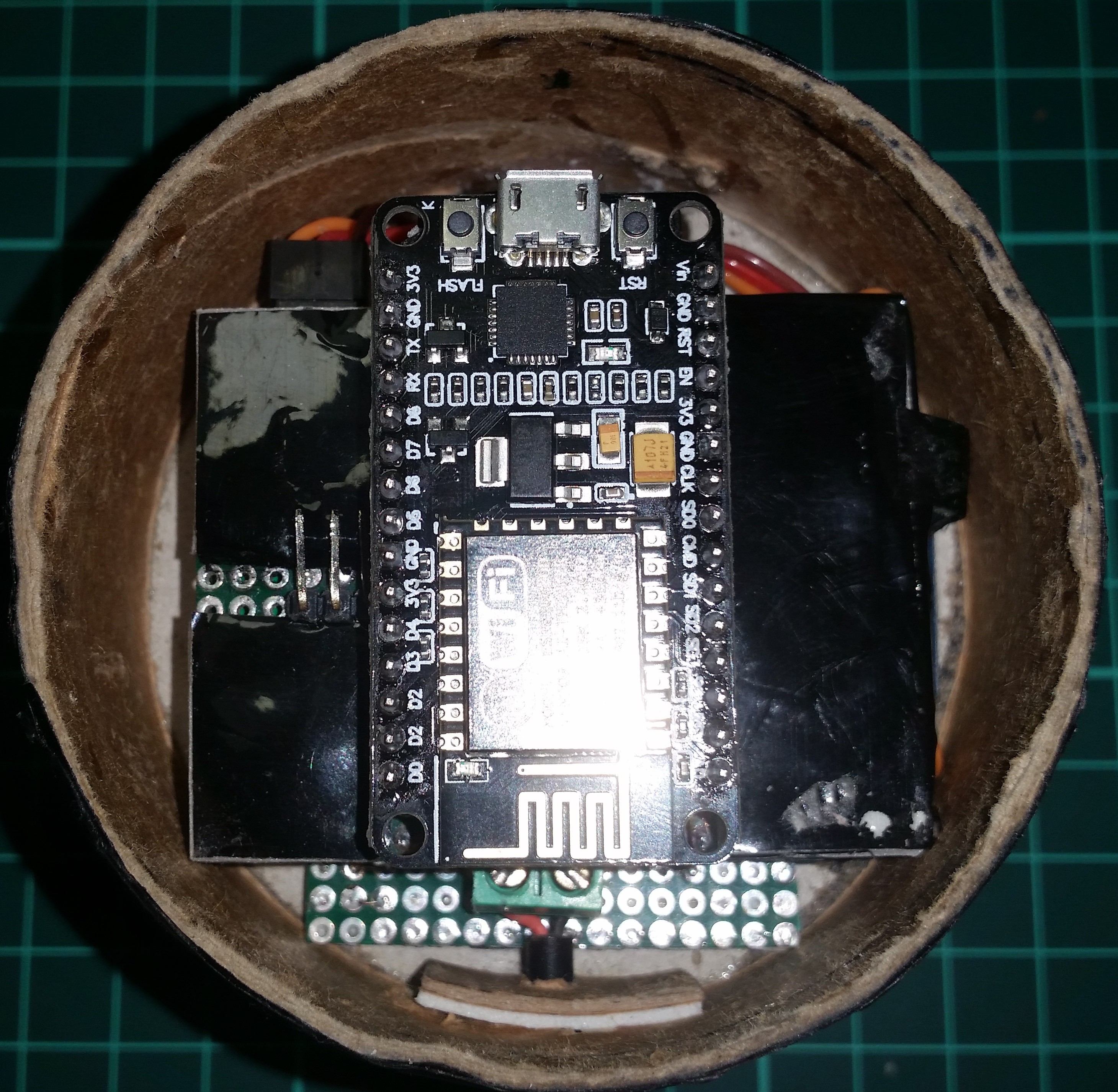
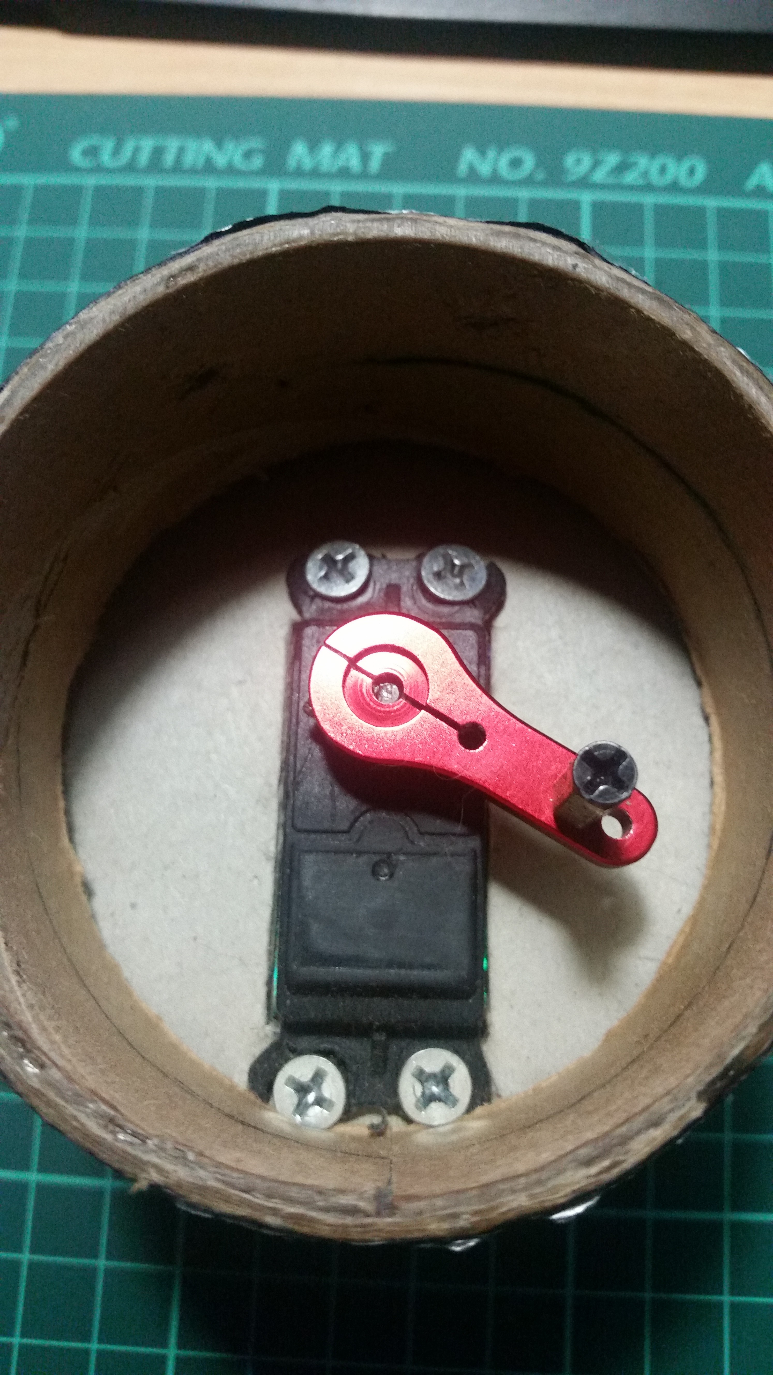
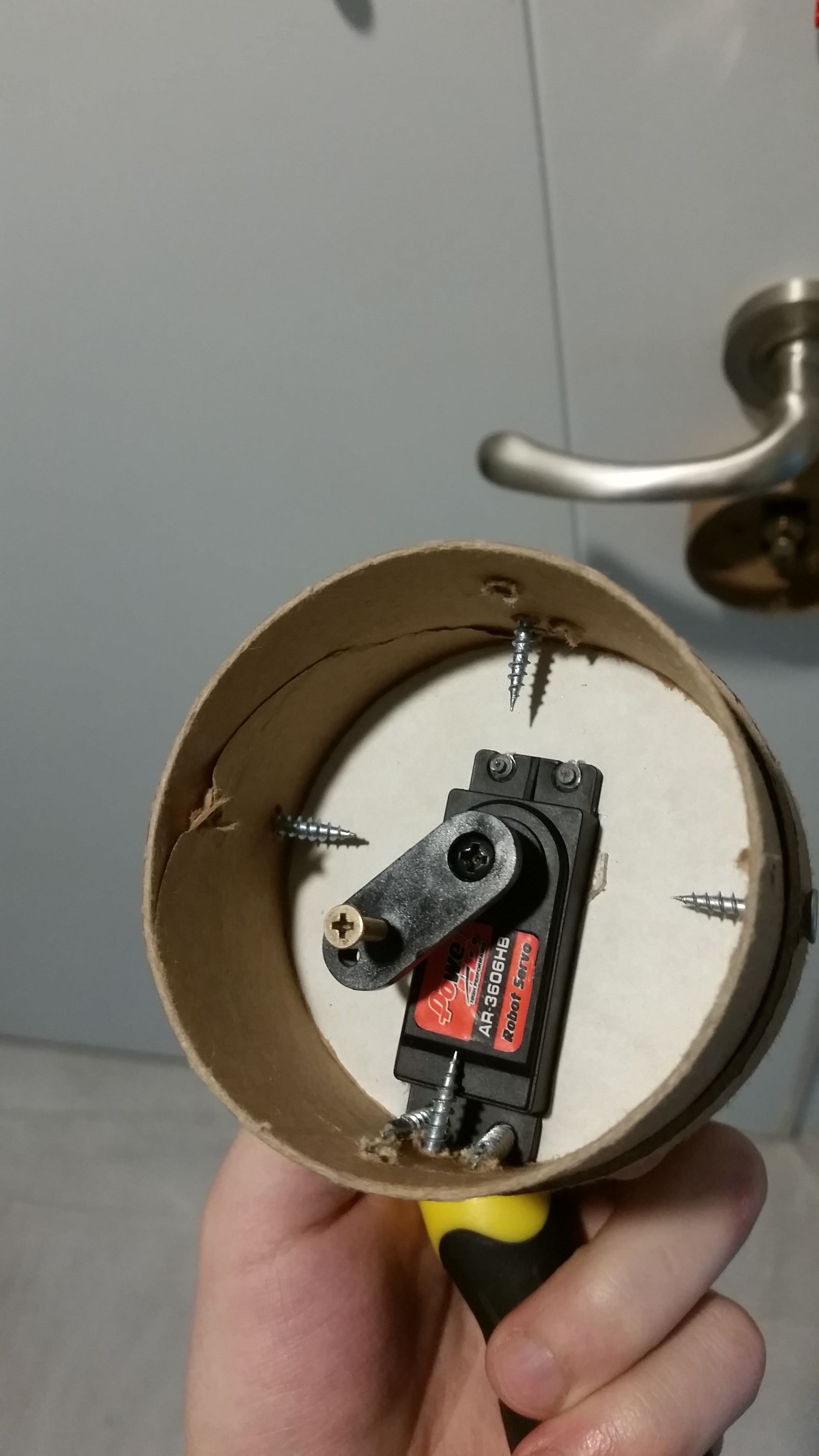
Concept uses a remote device to trigger the lock cylinder to be turned 360 degrees to both lock, unlock or open the door by using an geared motor which is attached to the inner face of the door.

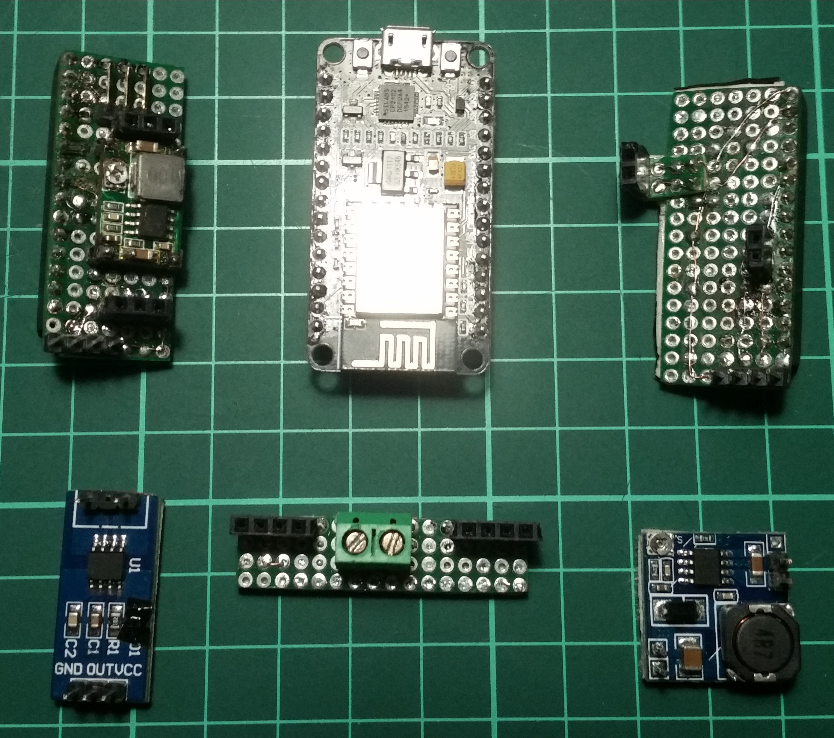
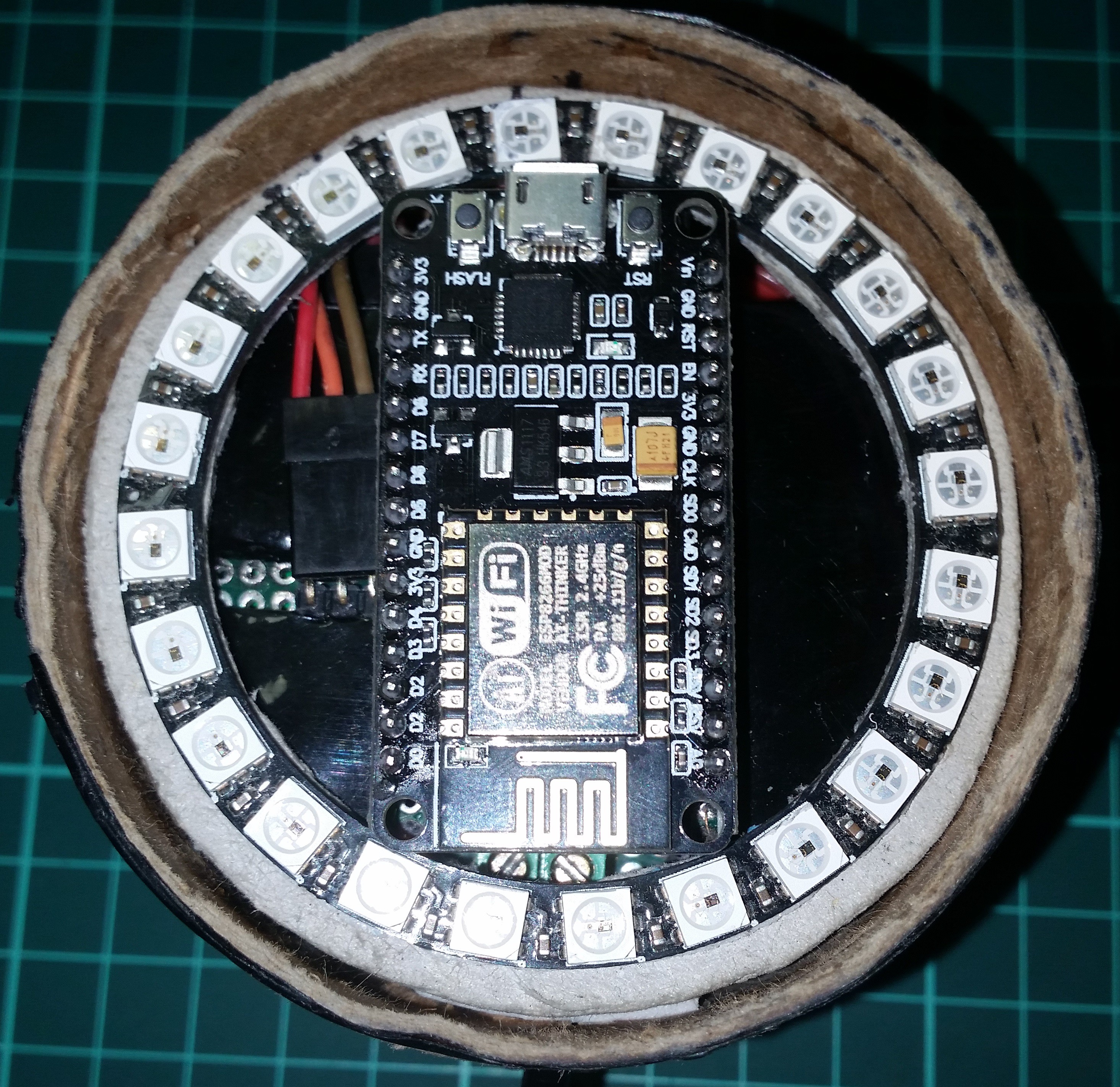
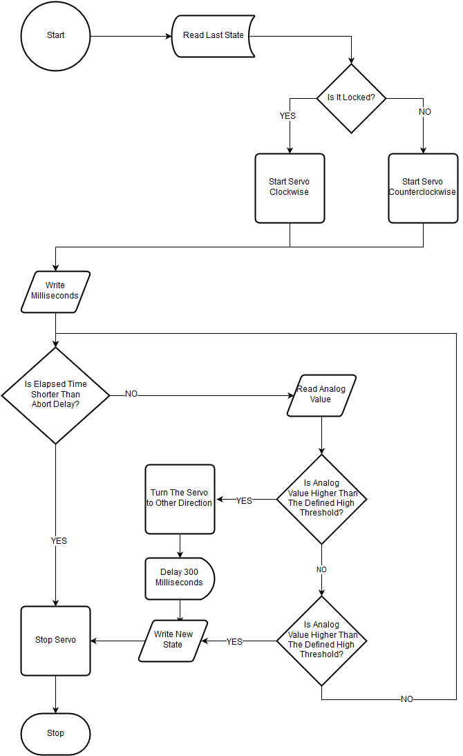
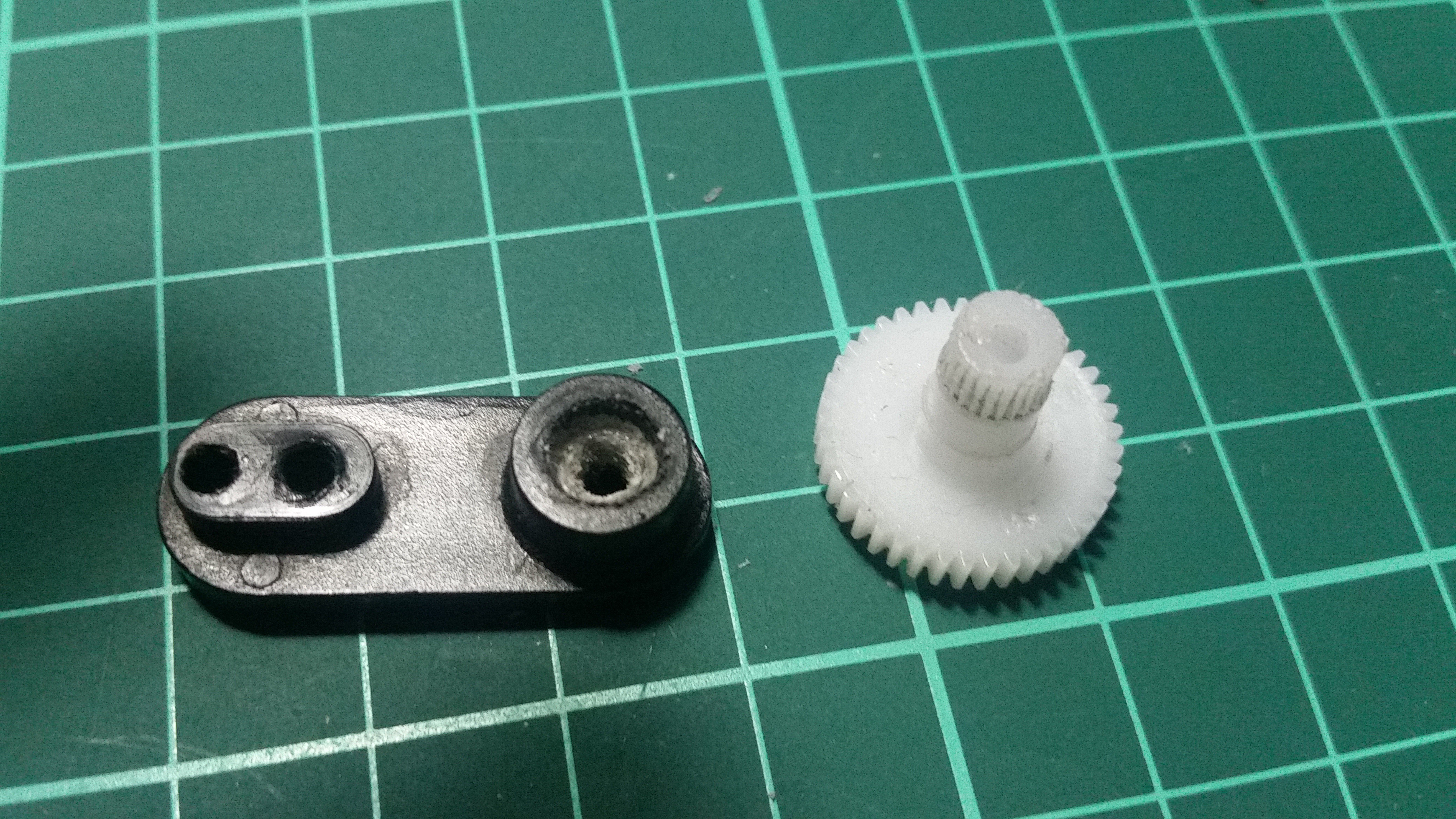
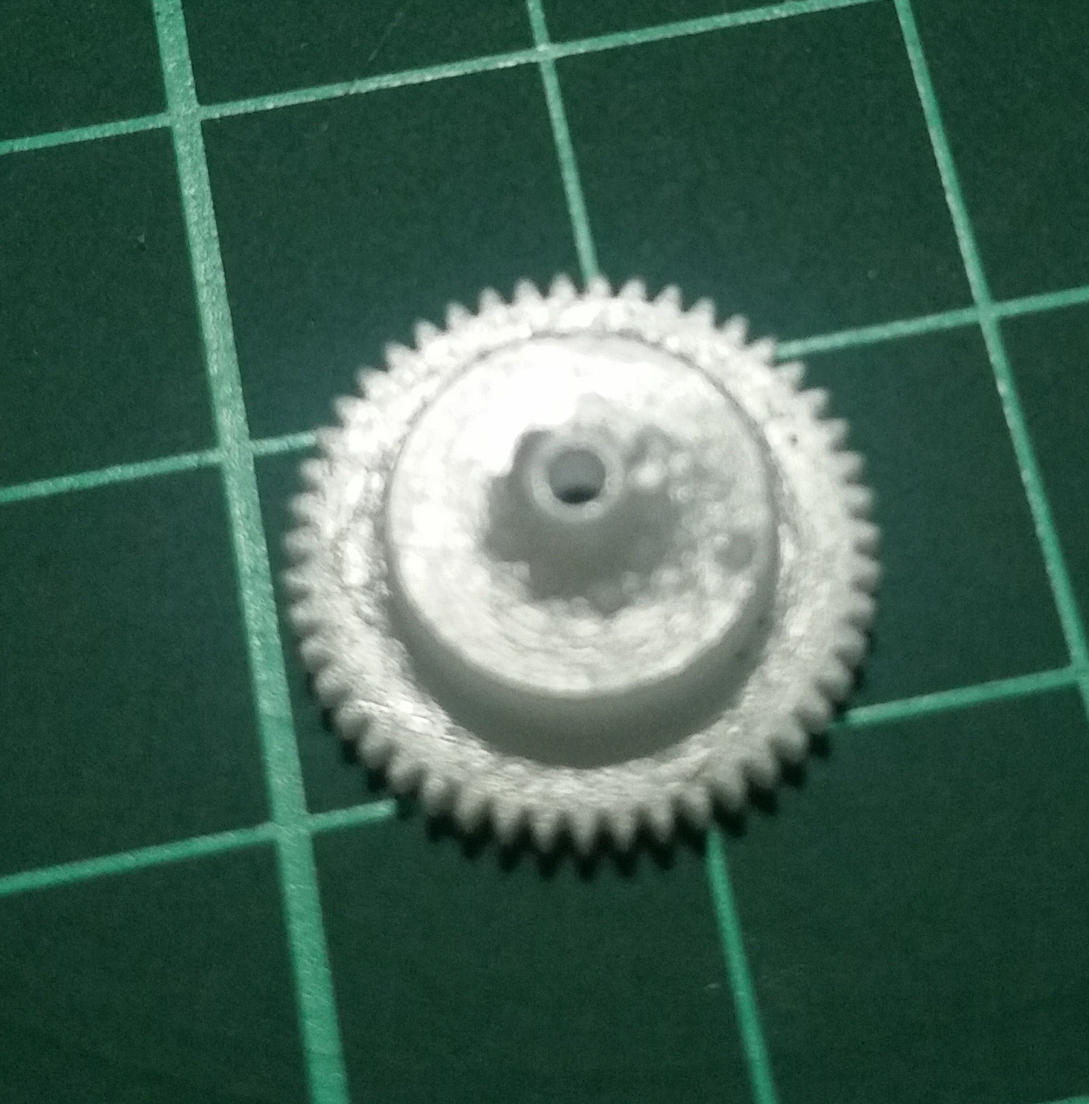
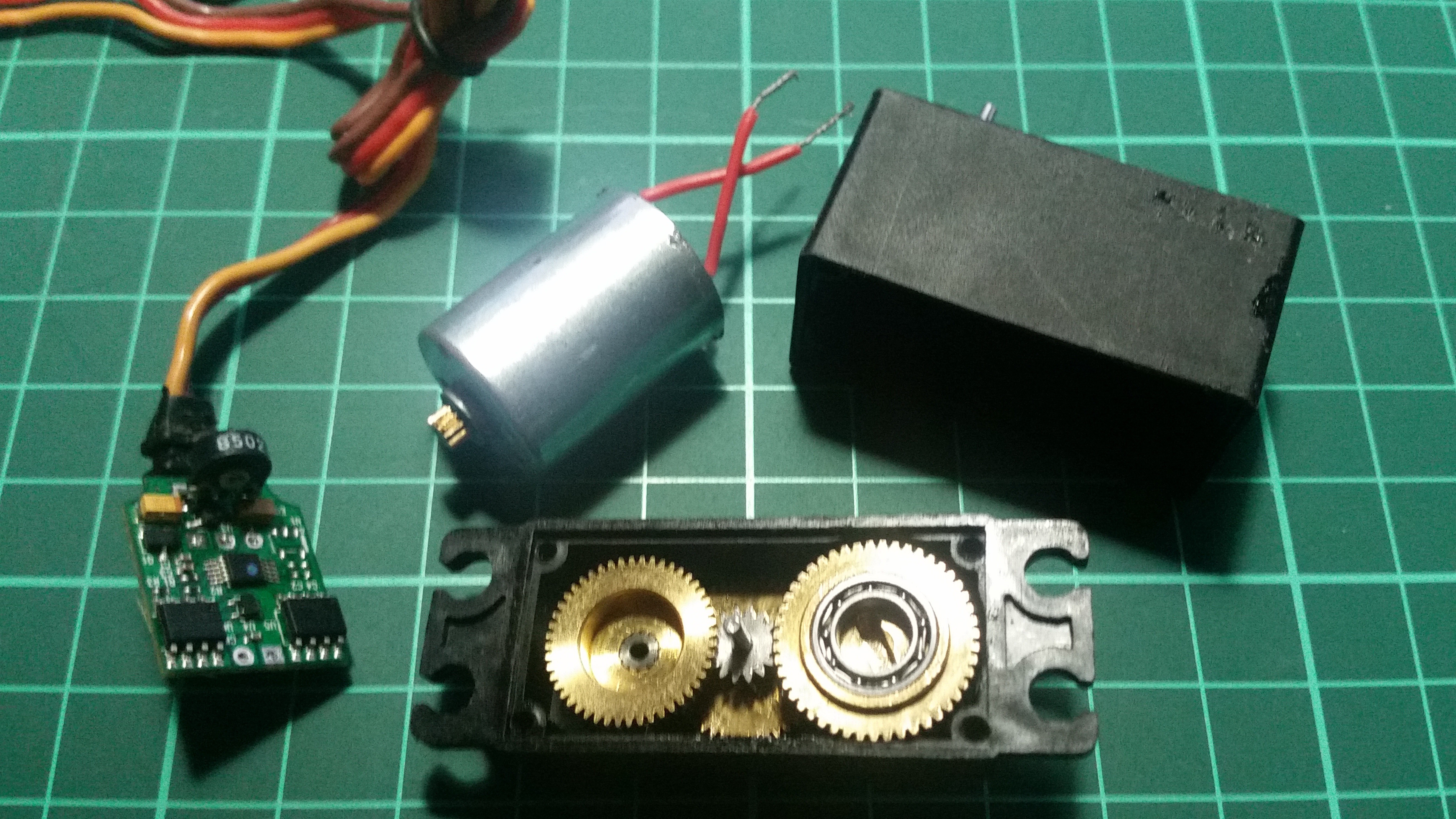
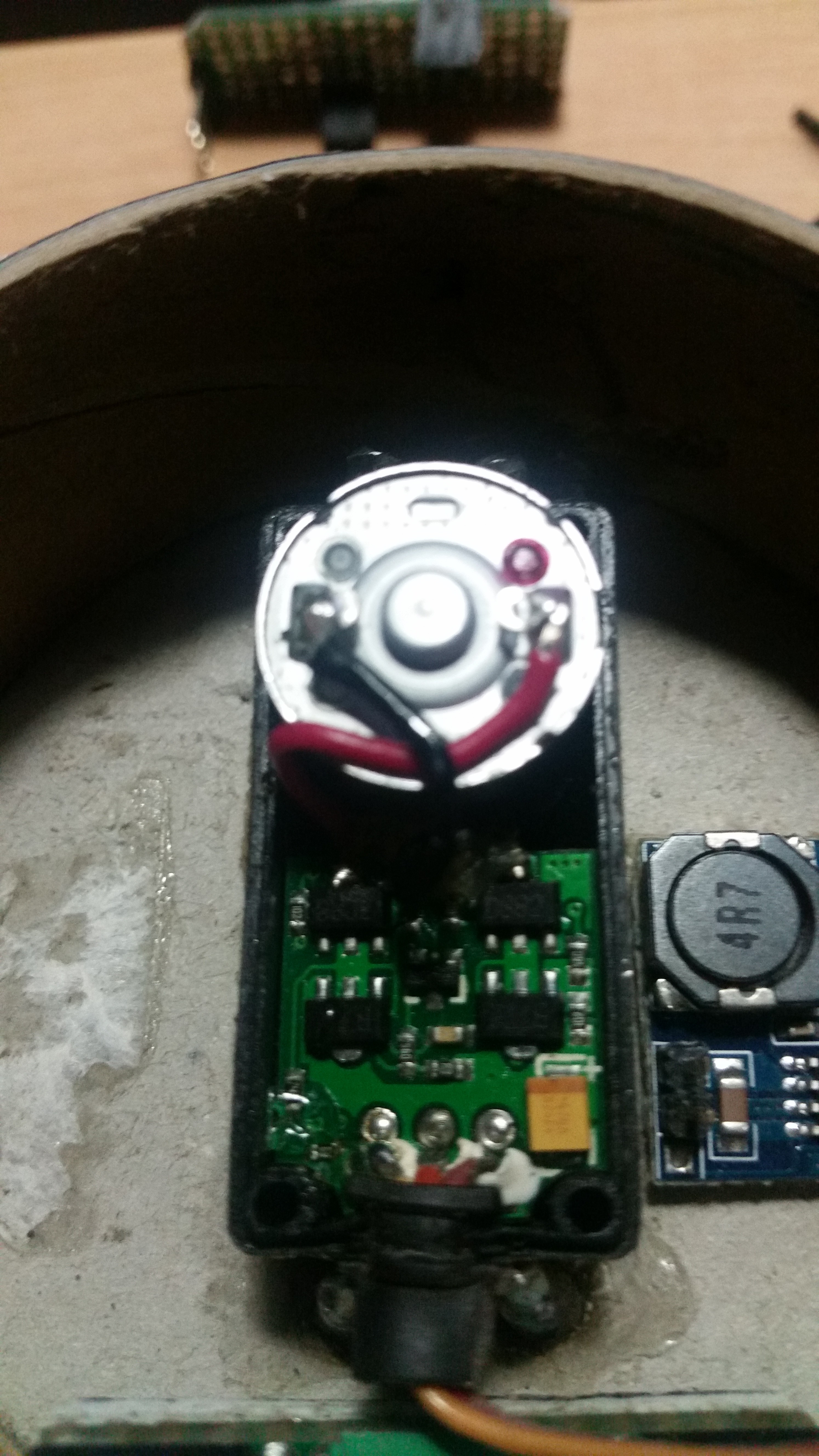
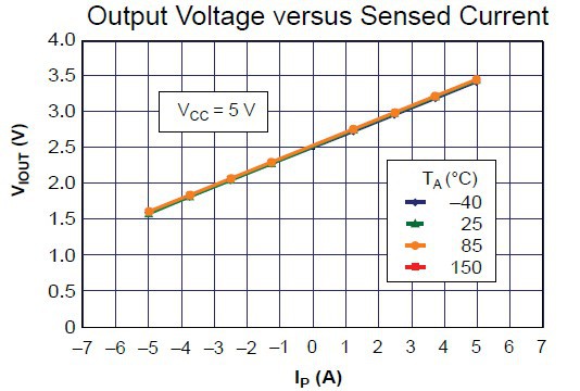
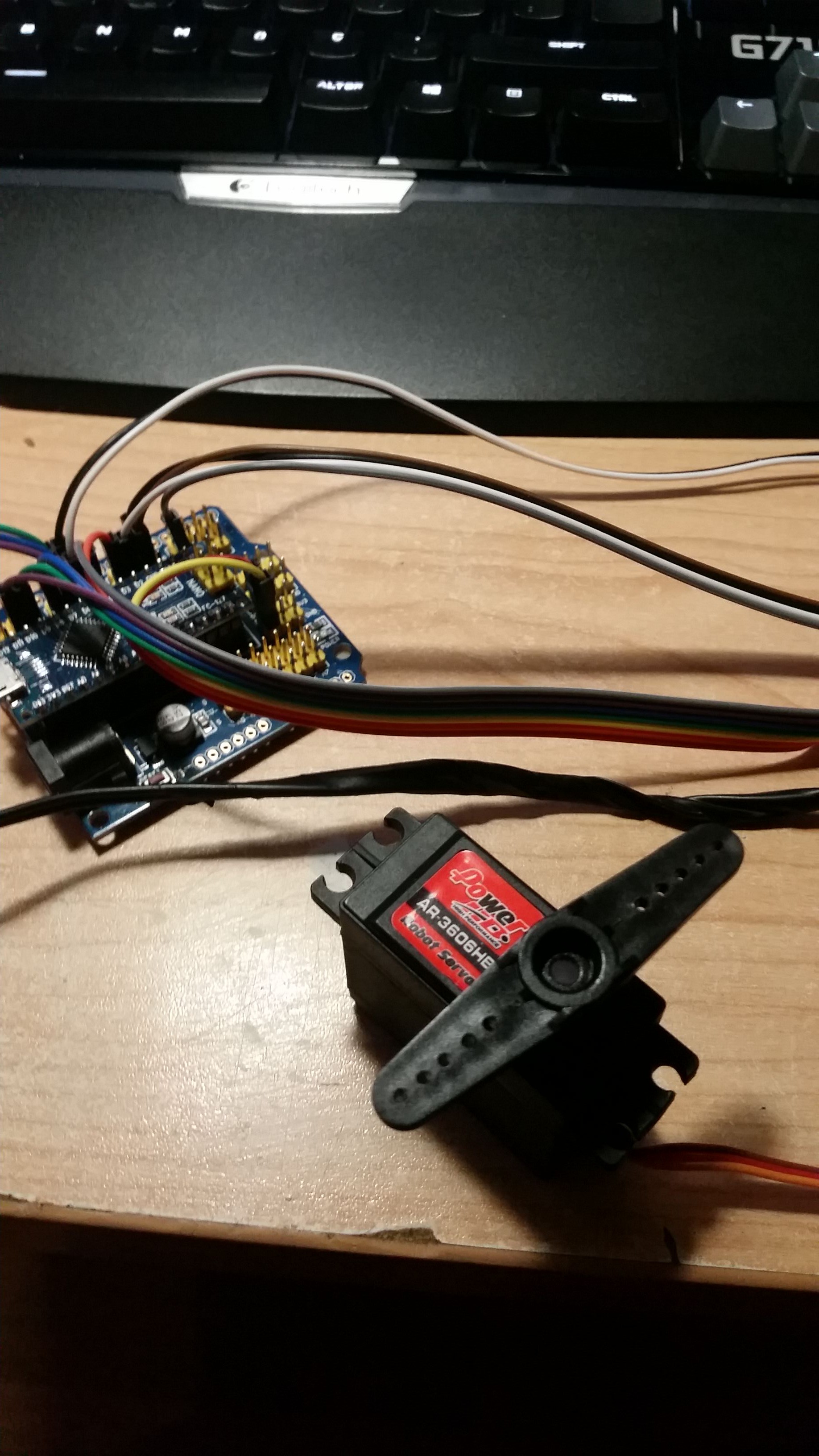
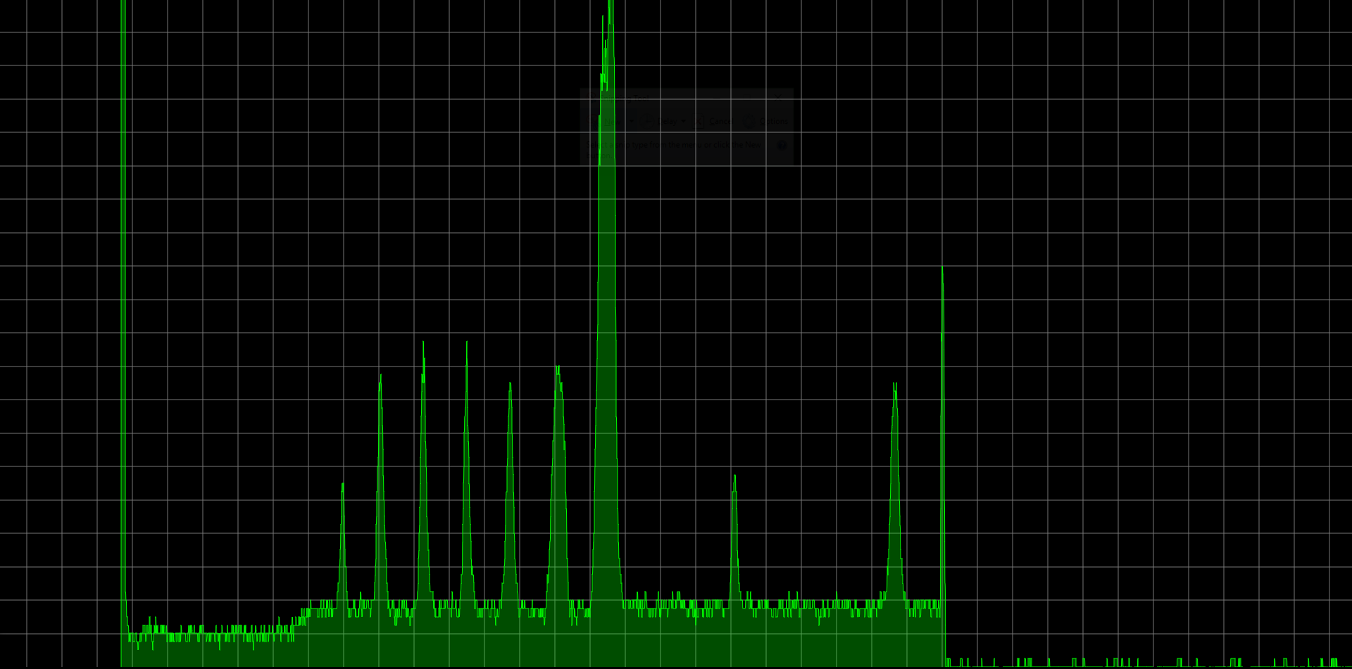
When I'm looking for a cheap way to position servo accurately, I've realized that I don't need to know the position of the servo. I only need to know when lock cylinder is triggering the mechanism of the lock. I know lock needs torque to trigger and torque requires enough current that I can easily measure with help of a small and cheap current sensing module. A current sensing module can be placed anywhere on the circuit and it allows me to build a more compact design.
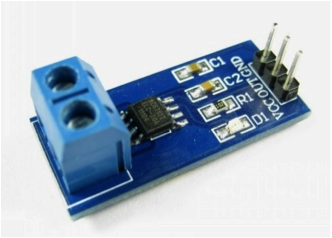
A hall effect current sensor uses electromagnetism to calculate the current. Since voltage never goes through the sensor, you can use it in both AC and DC. Sensor gives an analog output, a voltage between 0-2.5v for negative and 2.5-5.0v for positive current readings. I can use a micro controller with an ADC to read voltage and convert it to current with a formula.
Current = Voltage You Applied / The Resistance of your Load
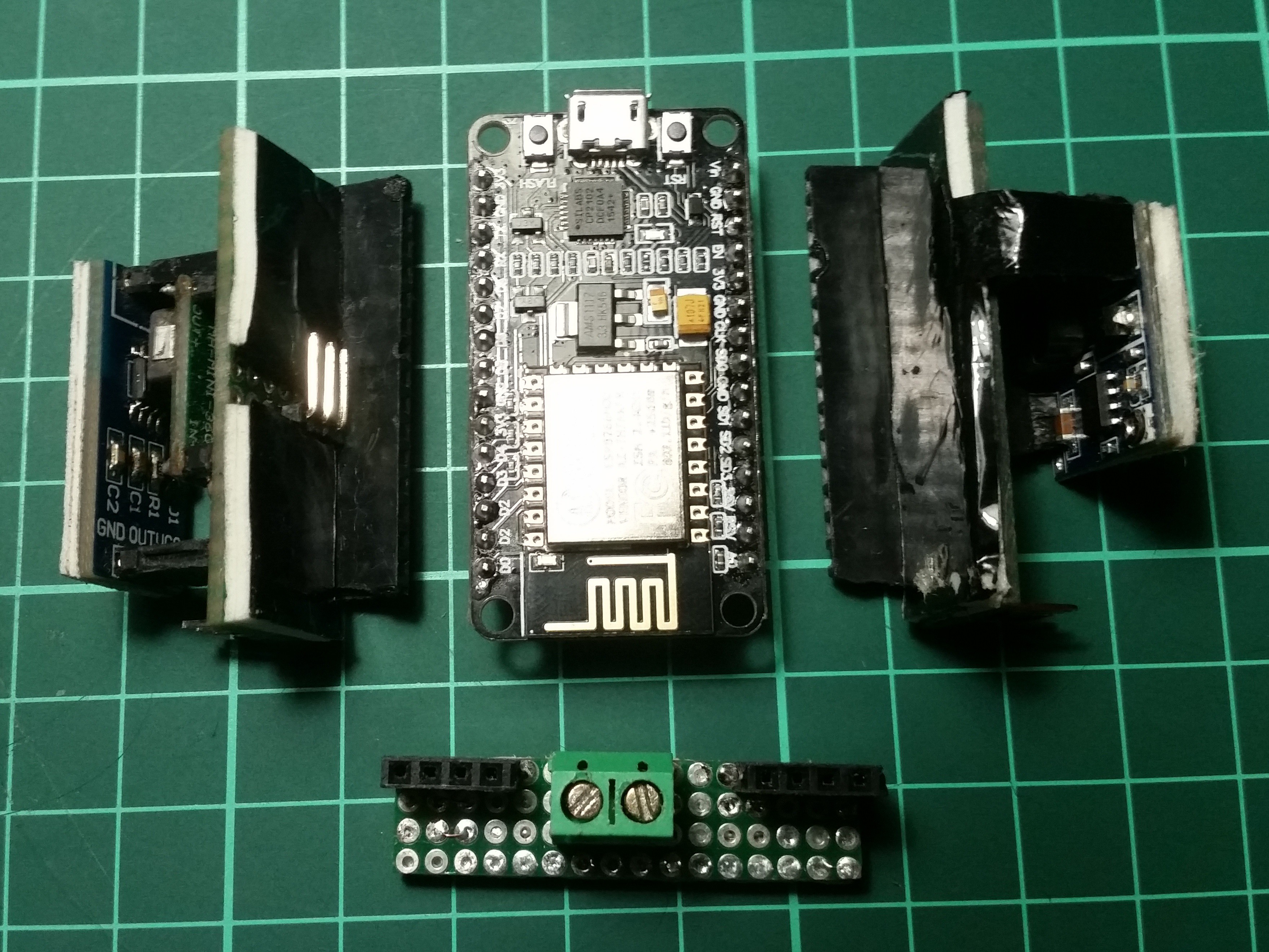
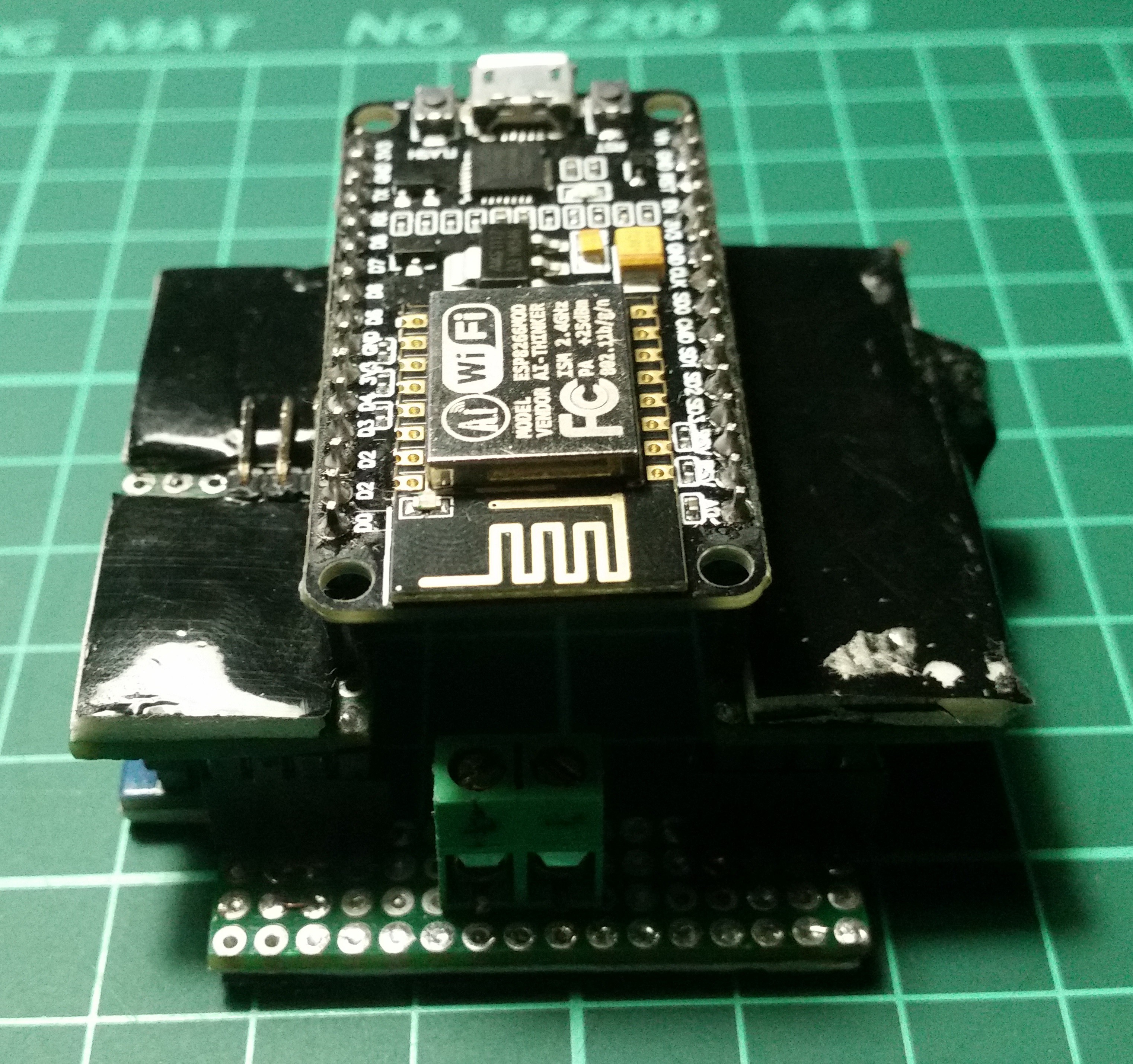
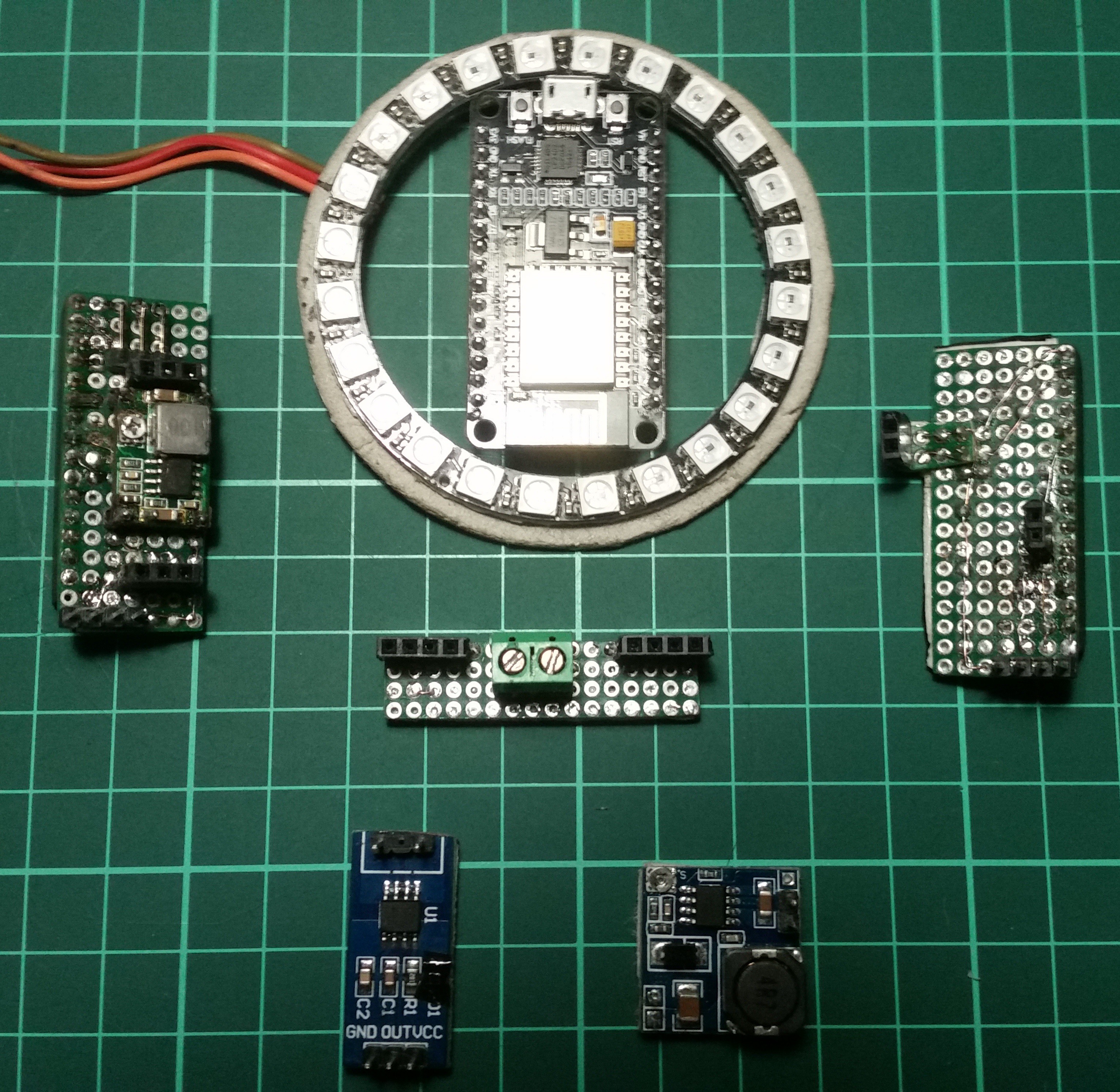
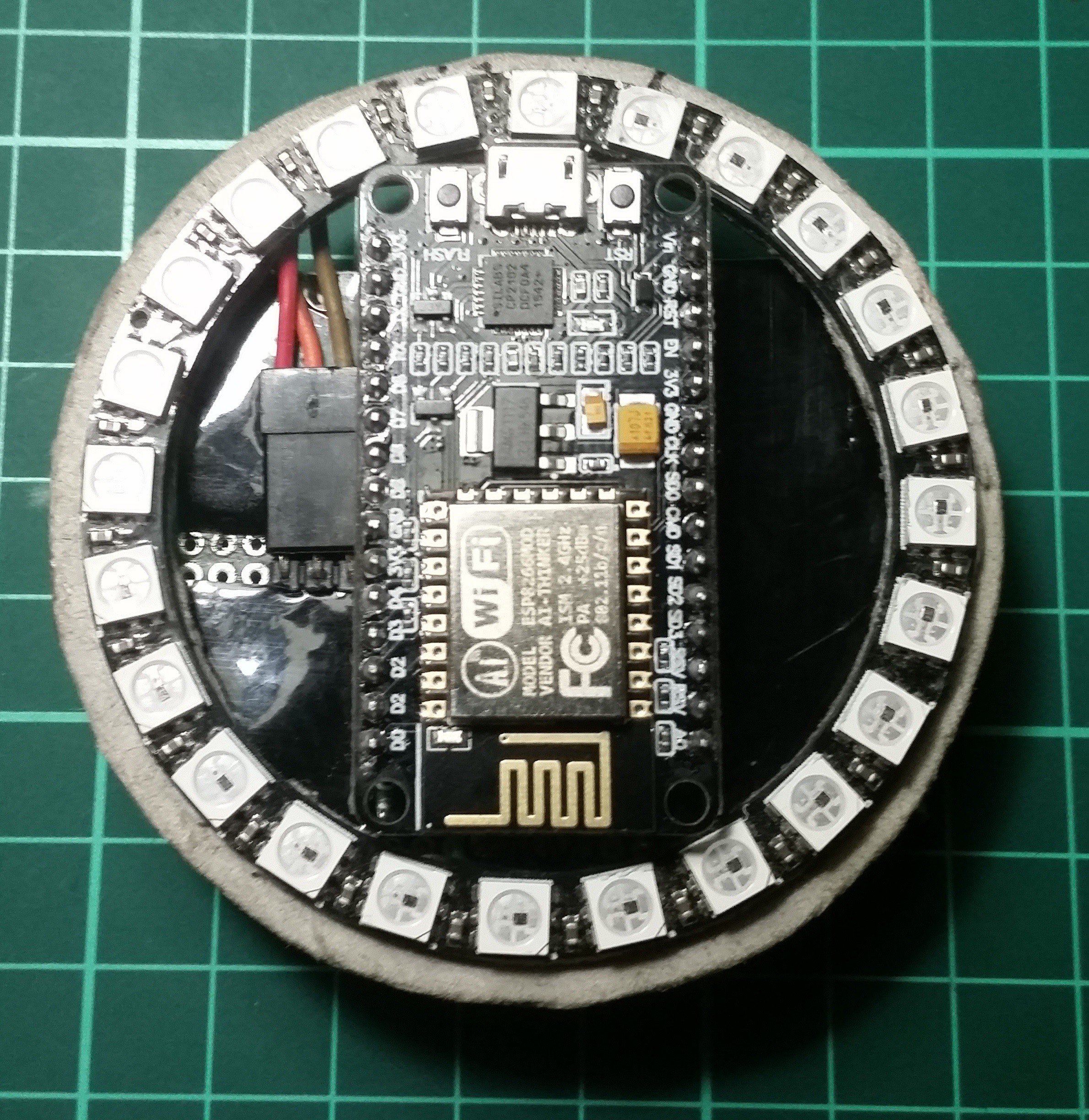
Micro controller
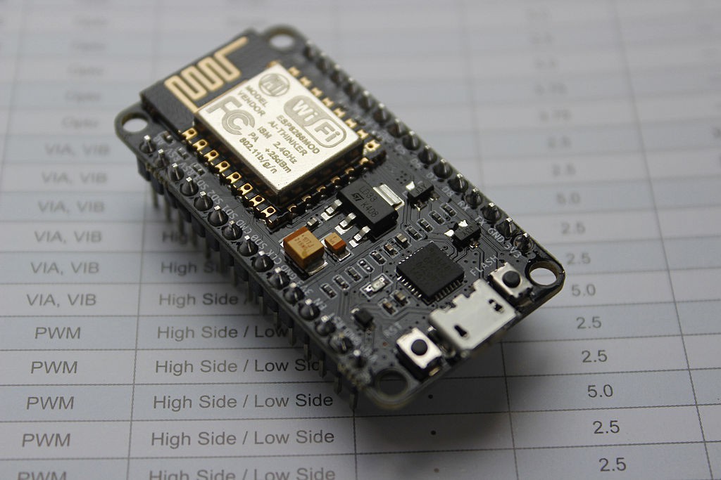
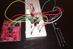
I choose ESP8266 module on NodeMCU Devkit because it handles all connectivity features that I need for this project on an single chip. It is small, cheap, it has internal ADC on it and there are ton of libraries available on the net.

 I found these
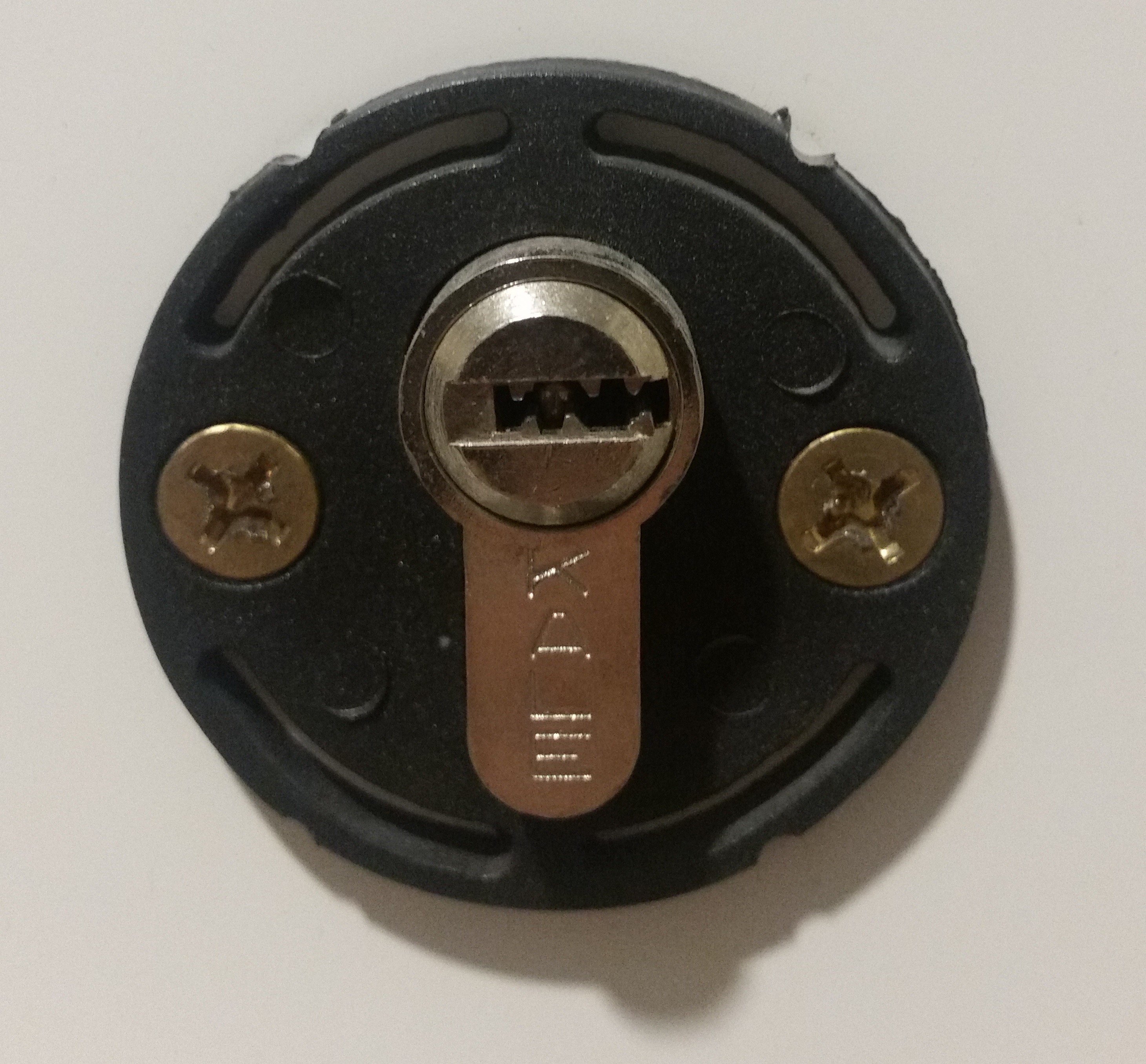


 Michael Haas
 jeromekelty
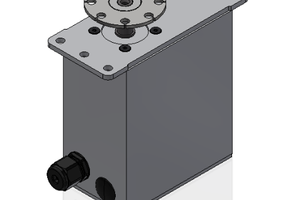
 patchartrand
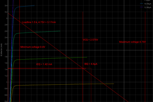
 Joseph Eoff
Hello,
What "Sensor board with servo regulator" did you use or what do you suggest to use for this design?