While every aspect of the project was being thought through, the mechanical team was simultaneously designing an assembly for the equipment.
This involves everything starting right from designing holders for every individual component like the lenses used, the mirrors, camera, etc. to designing a casing to house all the components together so they’re intact, safe and also easy to be held.
To make each of the parts of the assembly, we majorly used 3D printing and laser cutting.
The lens, mirror, camera and light source holders are designed such that they hold the mirrors, the lens, the camera and the light sources in place, such that they stay at an optimal distance to get the most desirable result light path. These parts were 3D printed and they easily fit into a laser cut outer casing that keeps the optic system undisturbed.
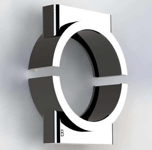
The lens mirror holders look like this:
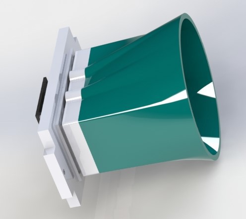
And the camera and Light source holder, with a new addition of
mount that helps remove glare and reflections:

done with the laser cut parts.

Take this for example. It is a support we designed for the batteries, primarily.

The device being self powered, has a strong battery back up. To hold the batteries in place, the following part was made, which easily screws on to the outer most case. this holds the batteries intact in their place, bu also serves as a base to the power bank PCB. And its location is such that its microUSB port very much accessible. So, all in all, the battery supports were designed such that they serve more than just one purpose, thereby eliminating the need for the more independant components. This helps assembling the device less time taking, compact and as optimised spacially as it can possible get!!
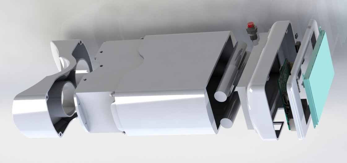
And now, this is an exploded view of the whole assemble of his project, we like to call OWL. This image shows exhaustively, the components of OWL.
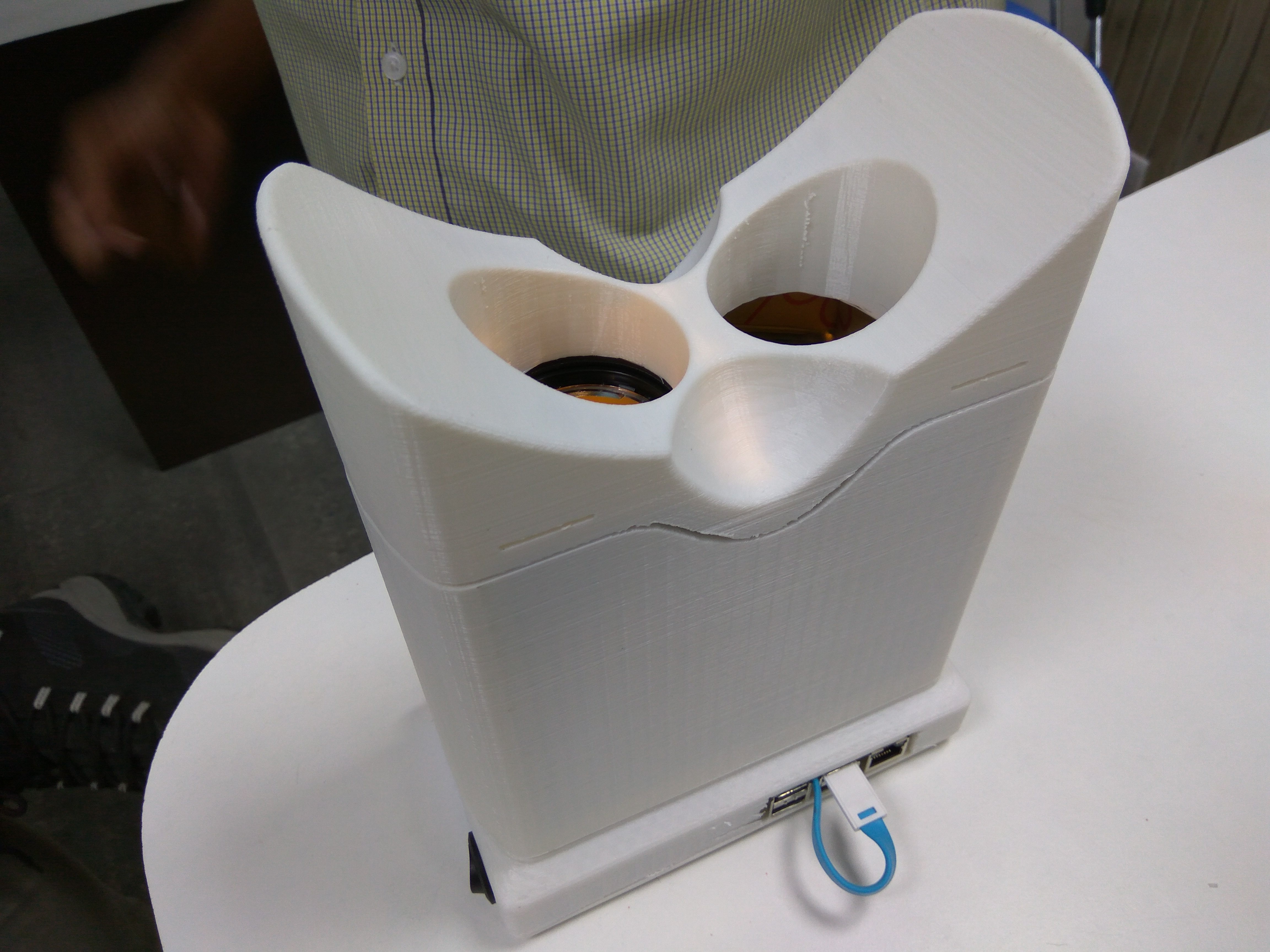
The most important elements of Owl in this housing. The optic setup. The design didn't take as much time as its printing did! It definitely turned out better than expected. An easy fit, the optic setup gracefully snaps into the 3D printed housing. This is one of the three primary outer most housing which are later combined into one simple and elegant looking case.
The assembly is designed such that every independently functioning element of the device can be detached separately without disturbing the remaining.
This here, is the assembling of the Raspberry Pi with the LCD screen, both in a separate case that snaps into the optics casing.
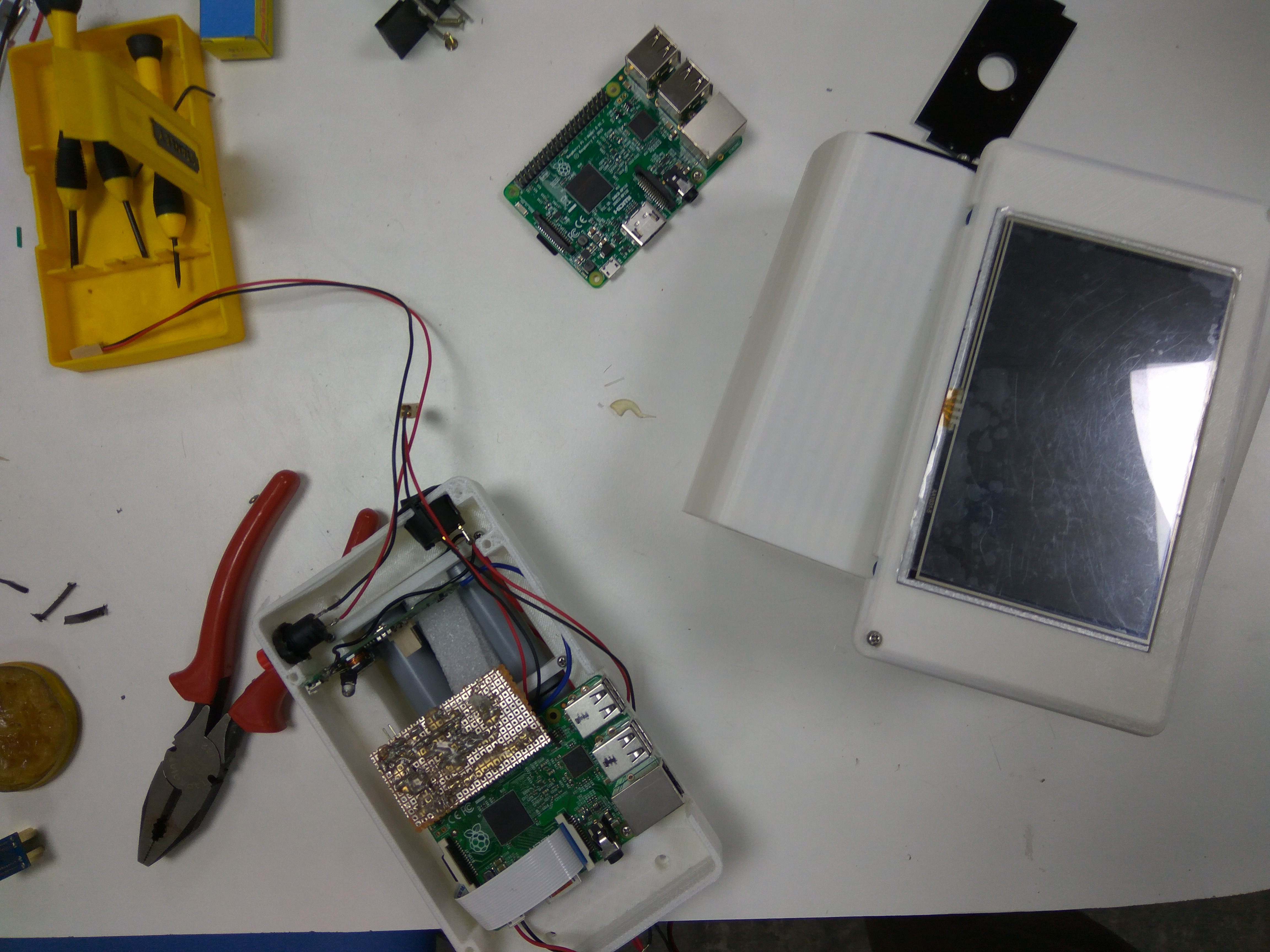
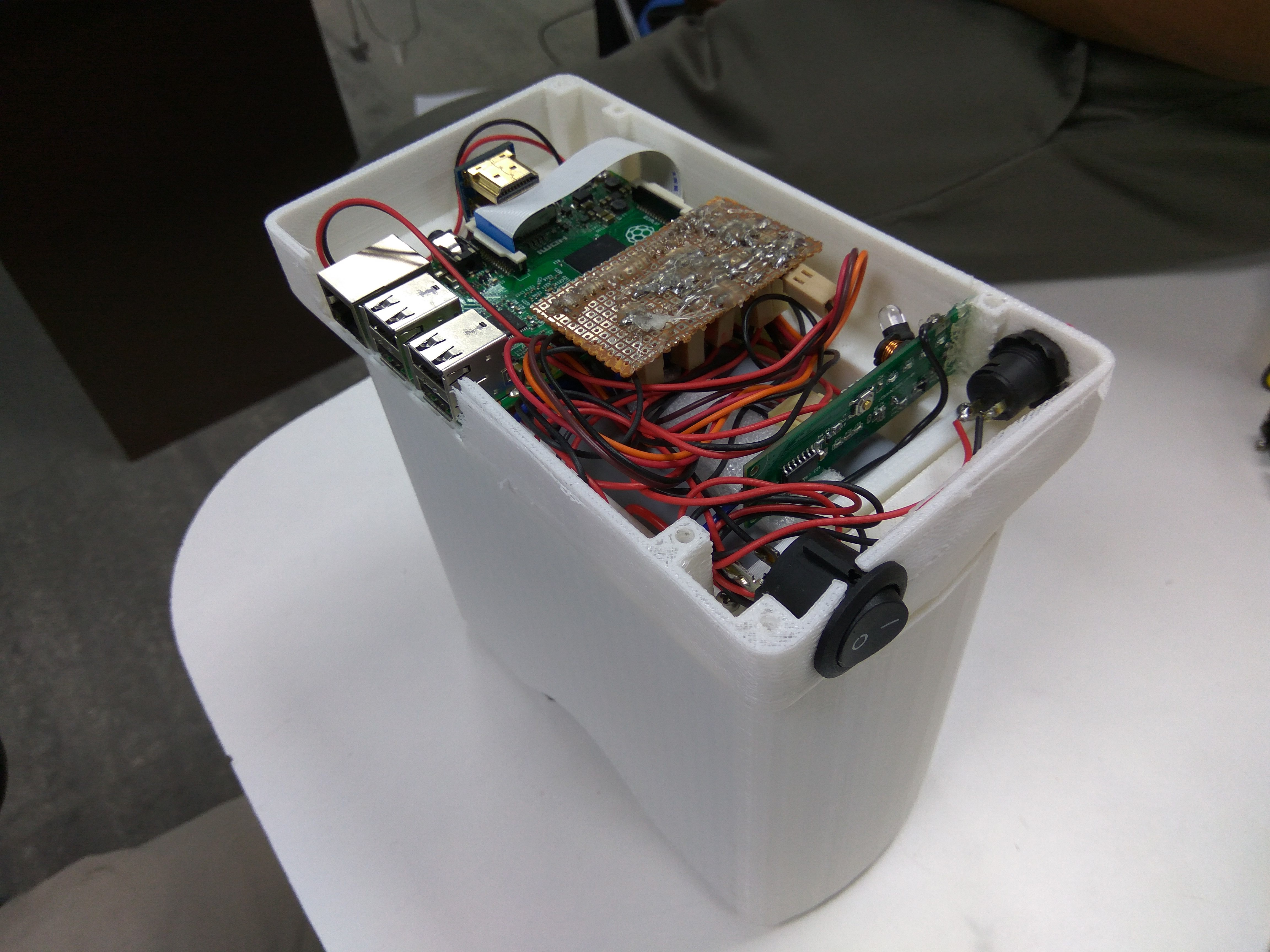
There are two switches externally accessible. The rocker switch is the master power switch. The push button switch in the first quadrant is an external access to click images of the retina. On this, is another cover that holds the 5 inch LCD screen, connected to the rPI via a HDMI connector.
These two sub parts of the assembly are now fit in with a third and final sub part, the eye gear. The eye gear is also 3D printed, but the designing of this part was the most challenging. While keeping in mind the spacial constraints as well as the fact that the optimal distance between the eye and the lens has to be maintained, the eye gear had to be made such as it has a comfortable fit on the eyes. In fact, because the device is flipped horizontally for capturing the second retina, i.e, of the right eye, the eye gear has to be symmetrical about the X axis. Still, the output seems to be reasonably good.
The image below shows the three sub parts of the casing before assembly.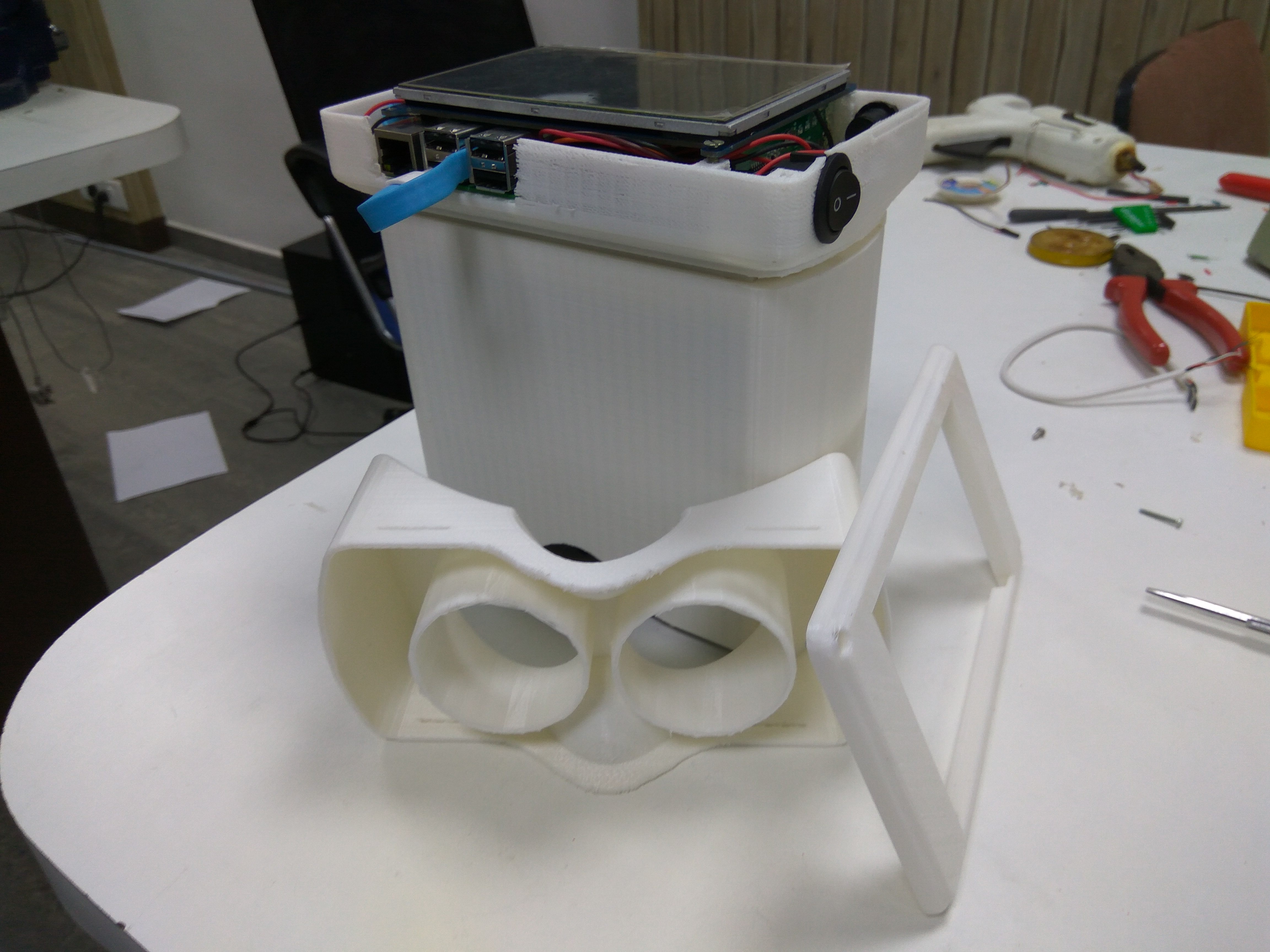 The three parts are easy to snap-fit, but also have screw fixes just to make it safer.
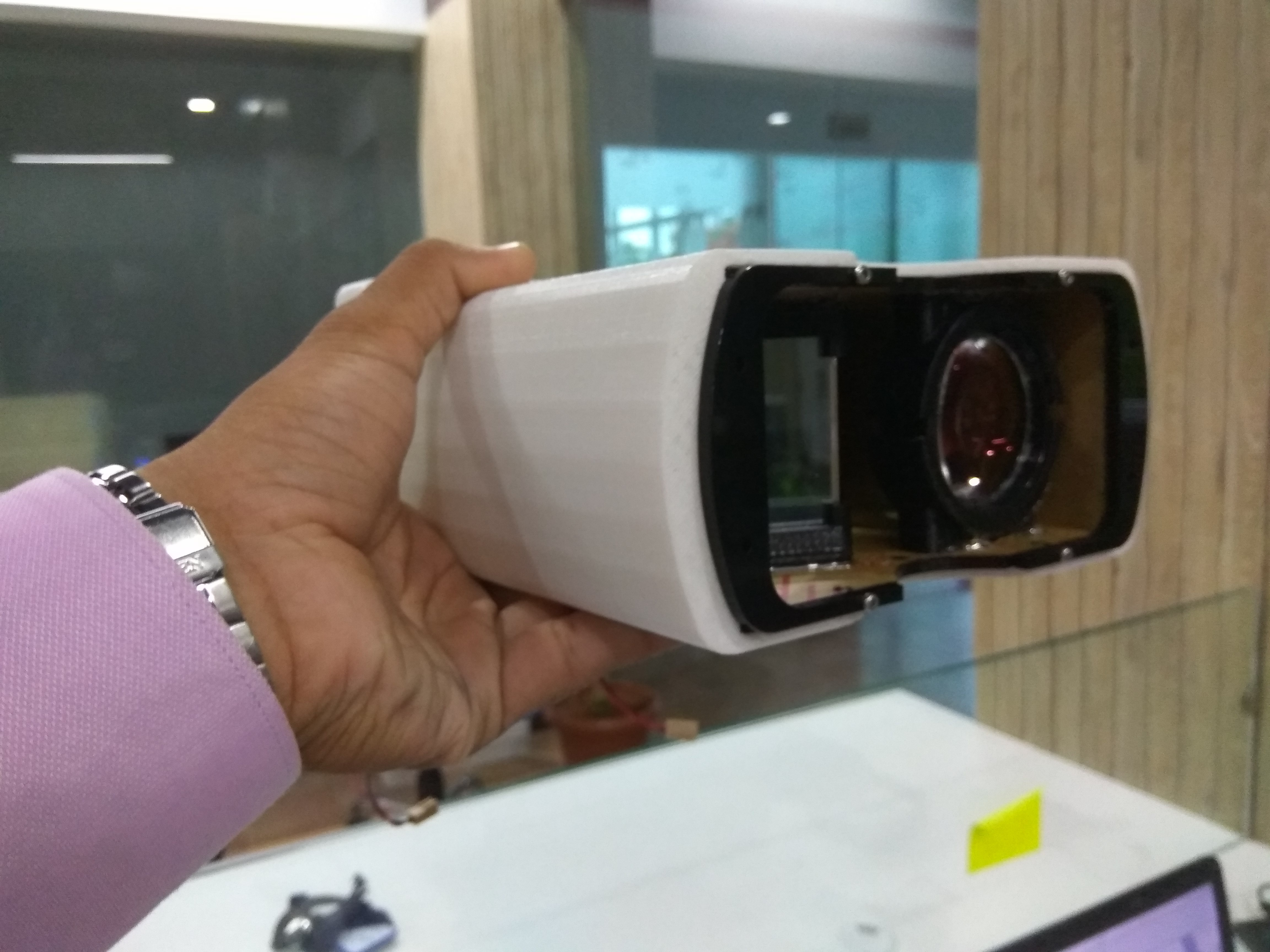
And this below, is an image of the final assembly.
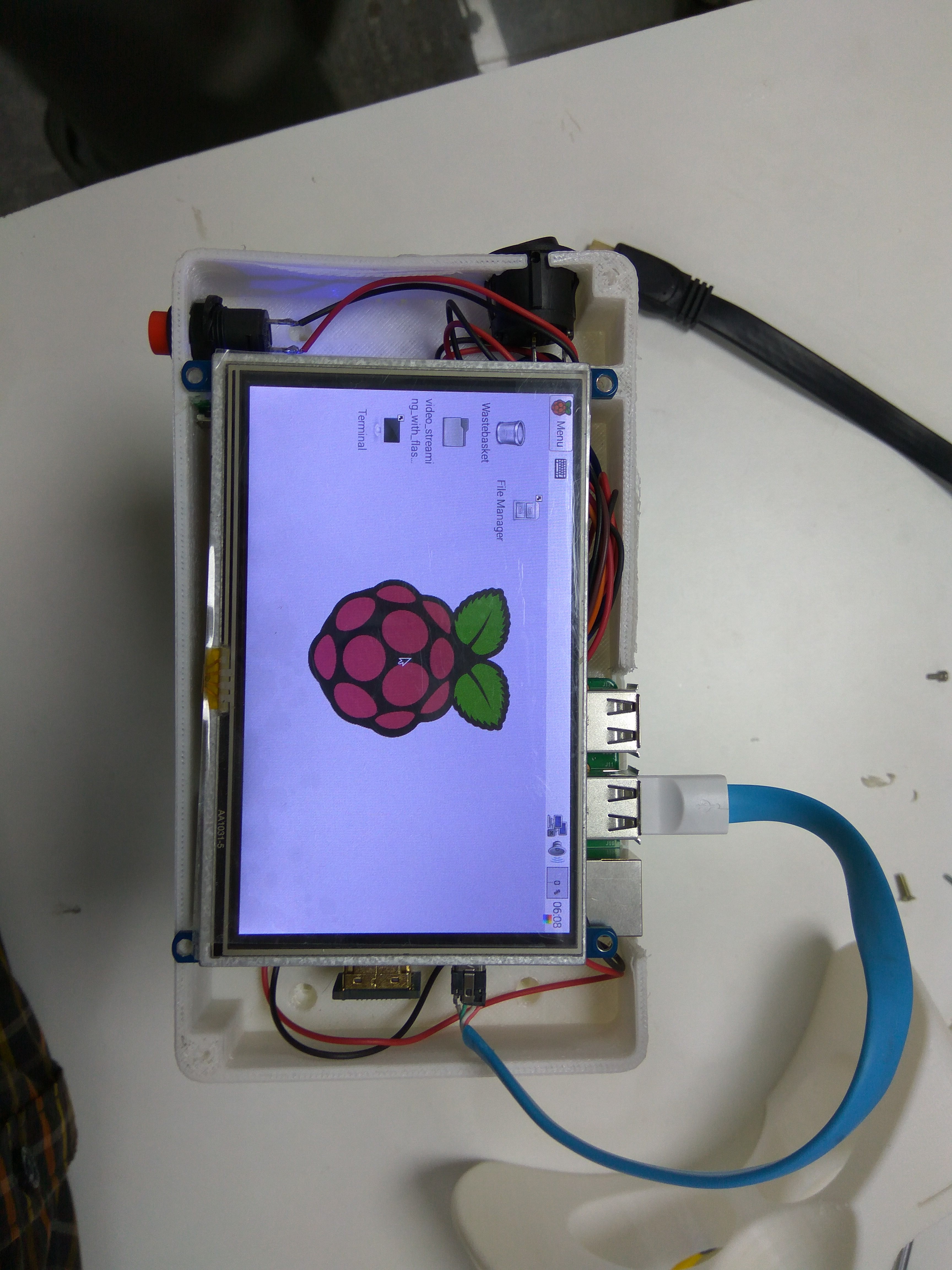
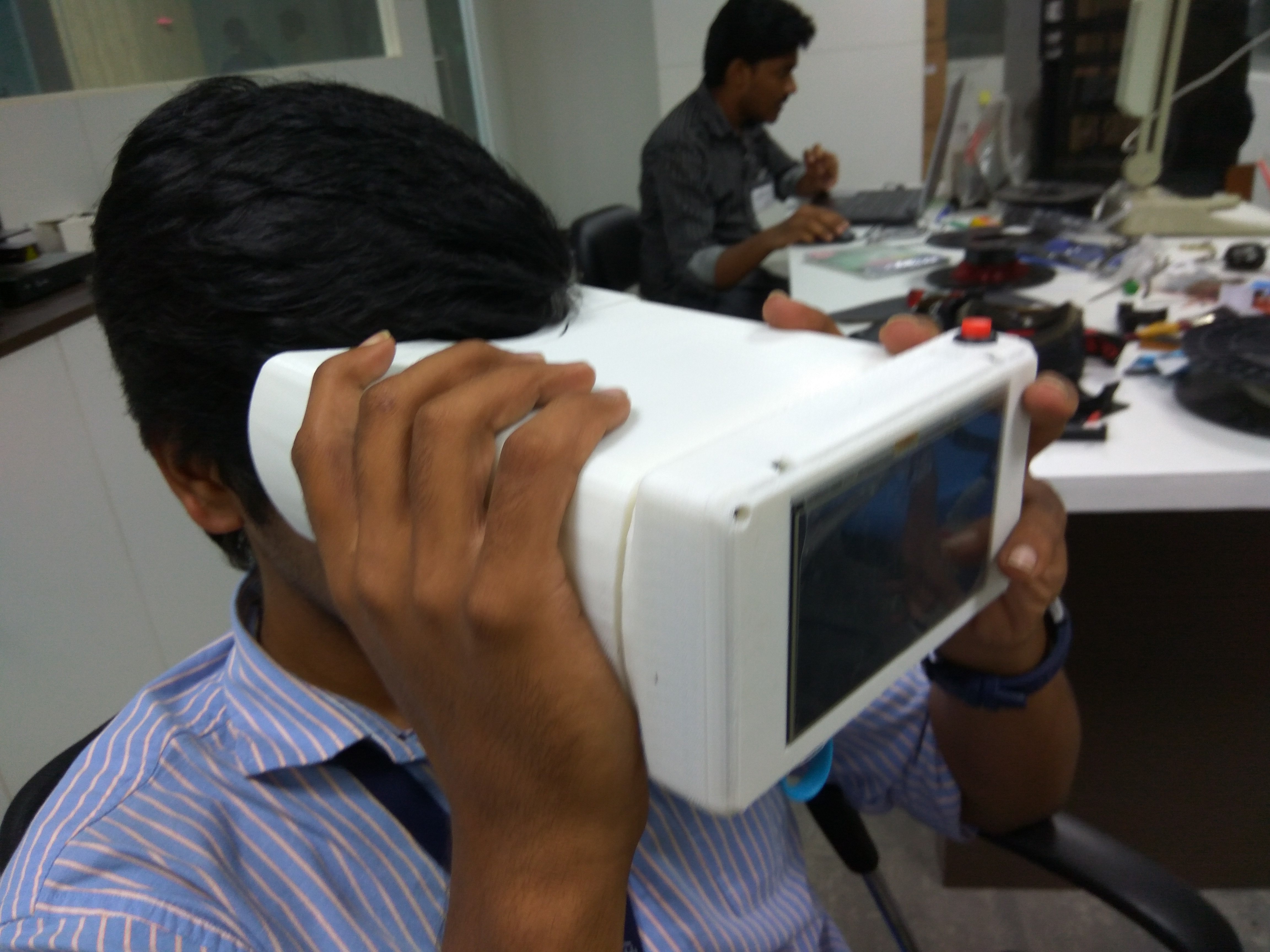 And this is how it roughly looks from the eye, when switched on.
 This is a testing of the device during the assembly. The retina doesn't exactly look like a piece of art, but that is because the test wasn't done with the optimal distance maintained, it was only a test for the switches and the screen display.
Better images and output of the device will be updated on the log later.
Discussions
Become a Hackaday.io Member
Create an account to leave a comment. Already have an account? Log In.