Hey all!
This is another project log to update the latest developments of OWL (Just in case you forgot, we call it OWL because, well, Open Indirect Ophthalmoscope, OIO).
So, since the last time I made a log, we’ve been working on-
- -making an elegant GUI for the device
- -improving the image quality, playing around with optics
- -removing the reflections caused in the image.
- -a polarizer arrangement to remove the formation of the spots
- -mosaic stitching.
This, besides the basic tweaks every now and then.
The GUI will be covered in detail by Ayush Yadav in a different build log.
Coming to the optics, we basically were experimenting different ways to somehow eliminate the bright spots being formed on the image.
Once the device was assembled and tested, we realized that the reflections wouldn’t stop forming unless we use a polarizer setup (Will be explained later in this same log).
Each LED was forming four reflections, two because of the mirrors and two because of the two surfaces of the 20D lens we use.
So we decided to try two things:
A glimpse in the implementation and methods of these two approaches areas follows:
Polarizer arrangement:
Polarizers are fundamentally optical filters, in the sense that they block waves of all polarizations except for one, giving a polarized light beam from a mixed polarized light beam.
The idea was to put polarizers of one orientation in front of the LEDs we use for illumination and another polarizers of perpendicular orientation on the camera lens. What this does is, when the light emerges from the LEDs and passes through the polarizers, it has just one polarization of the light passing through. And the camera has a piece of polarizer perpendicular to the orientation of the LEDs. So the spots will sure form, but the camera won’t detect them. Because the polarizer (in front of the camera) will block that polarization of light. So although the spots do exist, they don’t show in the image captured.
For this, an assembly was 3D printed. With the dual purpose of holding the LEDs in their calculated place and also housing safely the polarizers in their place, the assembly has two parts, elegantly snapping into one another. This is then screwed onto the camera holder. The image shown is of the final iteration that had been used.
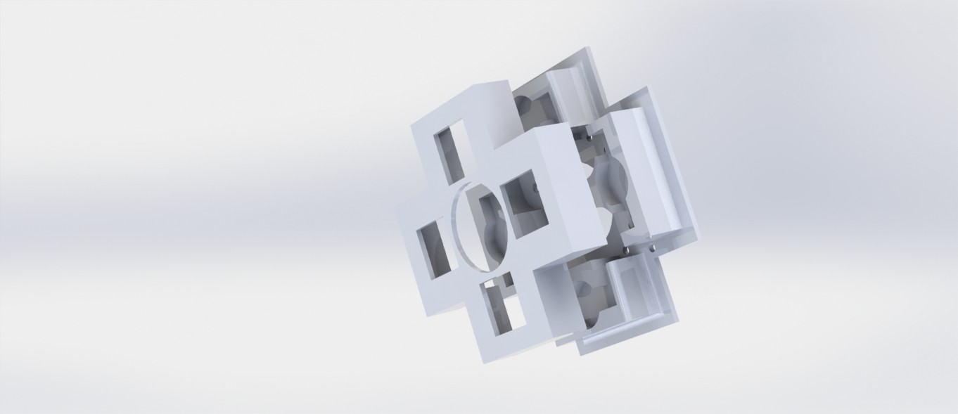
And this is an exploded render of the camera assembly with the hood, the LED holders, etc.

Like we expected, the polarizer assembly worked. The spots did not appear in the images. But we had to scrap the idea anyway. Because for some reason the brightness was hampered. We could visibly see a ‘+’ like shape form in the image which was because of relatively poorer illumination in that part of the image. We’re guessing this has something to do with the fact that our eyes also have a very thin layer of polarizer on them.
Mosaic-stitching images
Out of ideas, we took the last resort. Stitching two images together. The plan was to two images with different LEDs on, thereby removing the areas of the image with the spots.
So, we tried it out with the initial two-LED system only to realize that it is pointless to stitch the images we were getting. This is because one of the spots forming by each LED were being converged by the 20D lens to an extent that they overlap. And when overlapping, stitching can’t possibly help.
So we then tried another illumination system, this time with four LEDs, two along each of X and Y axis, and then switching two LEDs on at once. That is, we switched the horizontal LEDs once and take an image and then with the vertical LEDs on, we take another image. Because the LEDs are now along perpendicular axes, the spots formed will be at an angle of 90 degrees, so making the images easy to stitch.
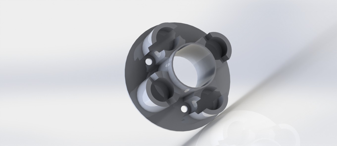
This is where we started using a 4 LED system. This again, gave a disappointing result. The horizontal LEDs hardly gave any illumination of the fundus. We gave it another try with reduced distance between the camera lens and the LEDs to the least possible. A render of this spatially optimized part is below. This also proved to be useless. So, we had to scrap this idea too.
Next, we briefly experimented with a shape X instead of + because we expected an X might give a better illumination when compared to the + orientation. Although we did getter better illumination, it came with the dark Plus at the center of the fundus again.
So, having no point in using 4 LEDs, we shifted back to the 2 LED system.

And that is what we’re using now too. With the hood in place, we’re getting two spots instead of four, which is progress, but we’re yet to remove the remaining two.
Discussions
Become a Hackaday.io Member
Create an account to leave a comment. Already have an account? Log In.