 insidecircuits
This documentation describes Open Hardware and is licensed under the
CERN OHL v. 1.2.
You may redistribute and modify this documentation under the terms of the
CERN OHL v.1.2. (http://ohwr.org/cernohl). This documentation is distributed
WITHOUT ANY EXPRESS OR IMPLIED WARRANTY, INCLUDING OF
MERCHANTABILITY, SATISFACTORY QUALITY AND FITNESS FOR A
PARTICULAR PURPOSE. Please see the CERN OHL v.1.2 for applicable
conditions.
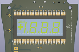
 chris
chris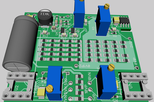
 Bud Bennett
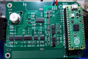
 NNNI
NNNI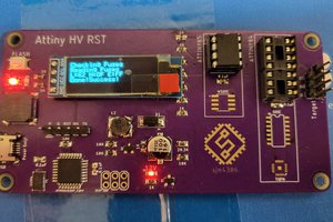
 sjm4306