 insidecircuits
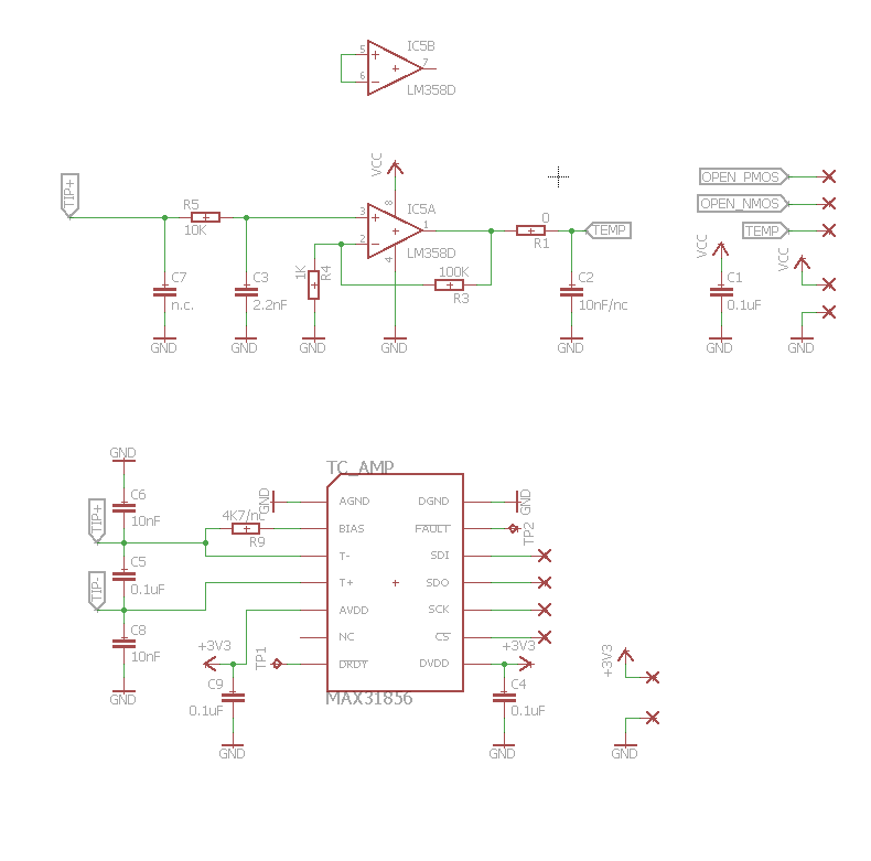
I started creating the schematic adding the MAX31856 and also included a simple op-amp (LM358) for backup just in case my solution won't fit together. The purpose of this is to directly amplify the voltage across the thermocouple and output a reading in volts proportional to the temperature.
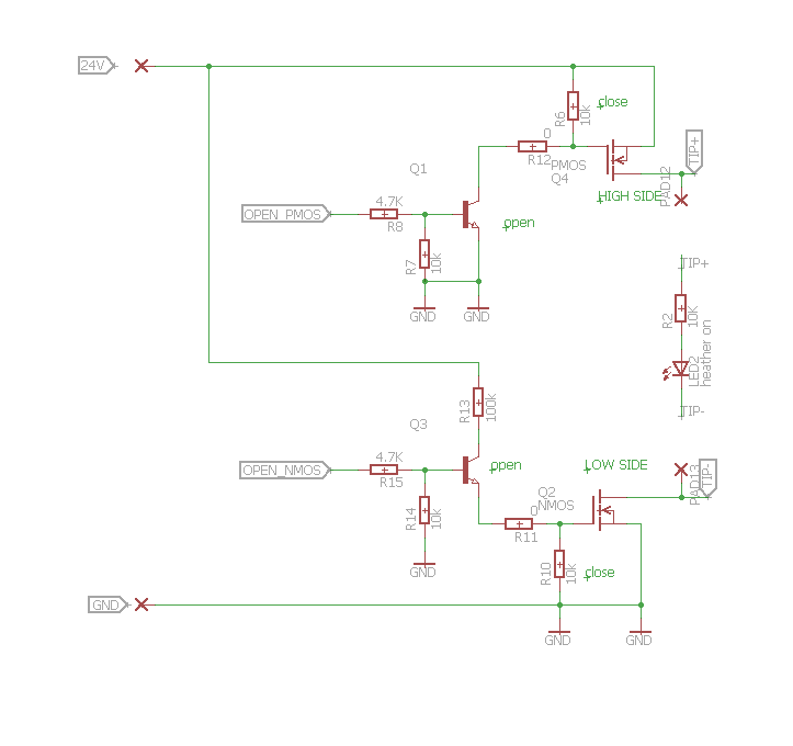
For the switching part the best solution would have been some relays, to completely disconnect the tip while reading the thermocouple so no external voltage would drop on the junction. I was thinking of some reed relays that have longer life than traditional ones but I dropped the idea in favor of a more elegant solid state solution using MOSFETs. I had to use a N-channel on the low side and a complementary P-channel on the high side (to avoid charge pump complications driving a N-channel high side). Also I inserted two driving transistors, the low side one also acts as an inverter so that the command signal will open/close both sides at the same logic level.
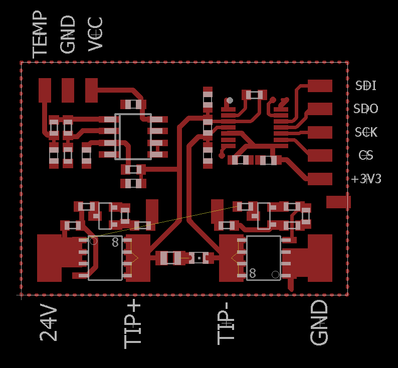
Here is the layout of the board that includes all the components above. Actually there is a mistake here on the sensing terminals (they are reversed) so it has to be corrected.
Discussions
Become a Hackaday.io Member
Create an account to leave a comment. Already have an account? Log In.