Based on prices online good candidates for GPS receivers for this project are:
- $10.50 u-blox NEO-6M – Older cheap GPS used by DIY Drones
- $14.25 u-blox NEO-7M – Newer version
- $20-27 u-blox NEO-M8N – Newest, supports concurrent reception of up to 3 GNSS (GPS, Galileo, GLONASS, BeiDou)
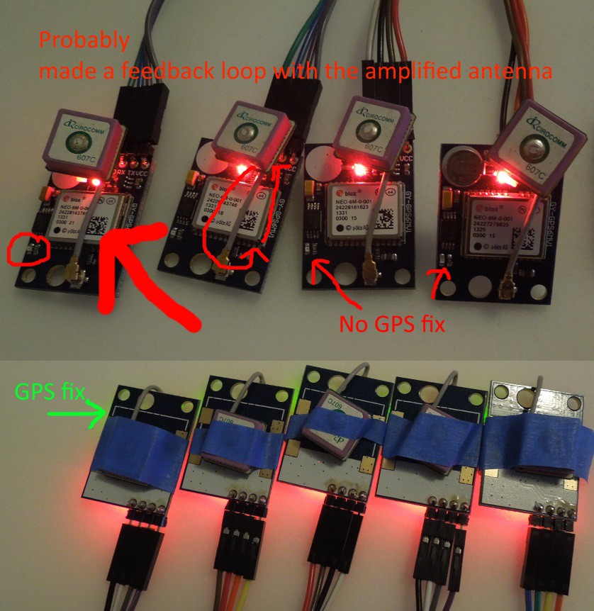
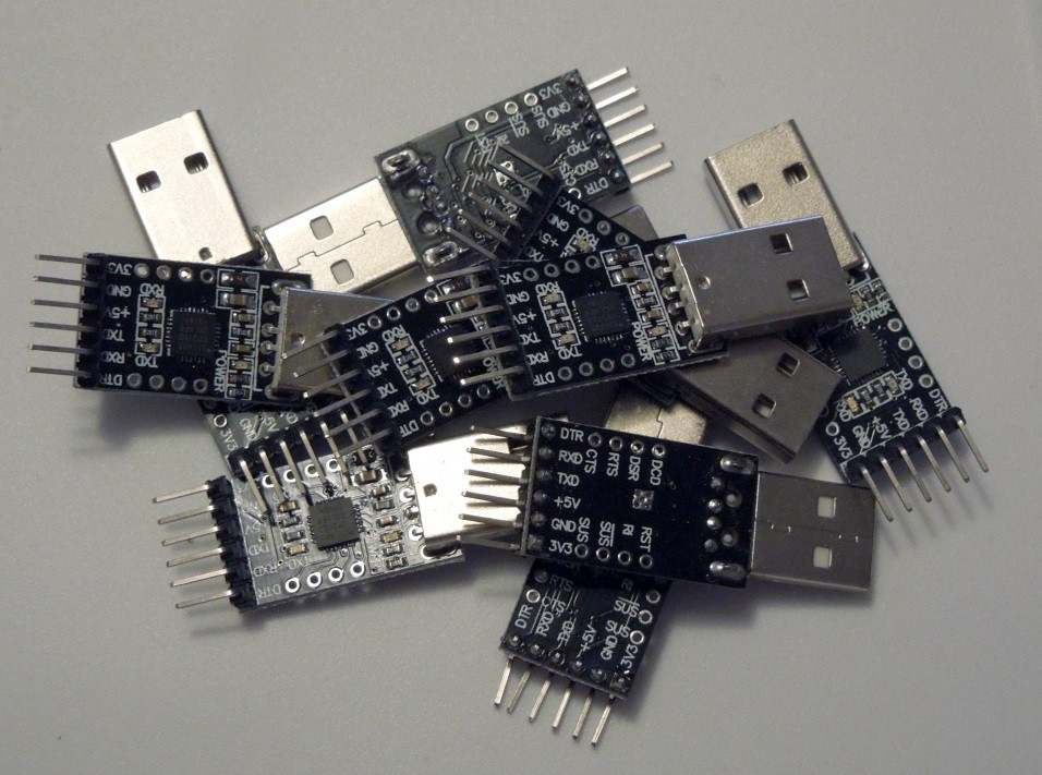
For testing I will use 9 of the GY-GPS6MV1 u-blox NEO-6M boards widely available online, and test a u-blox NEO-M8N in case it is significantly better.
Plan
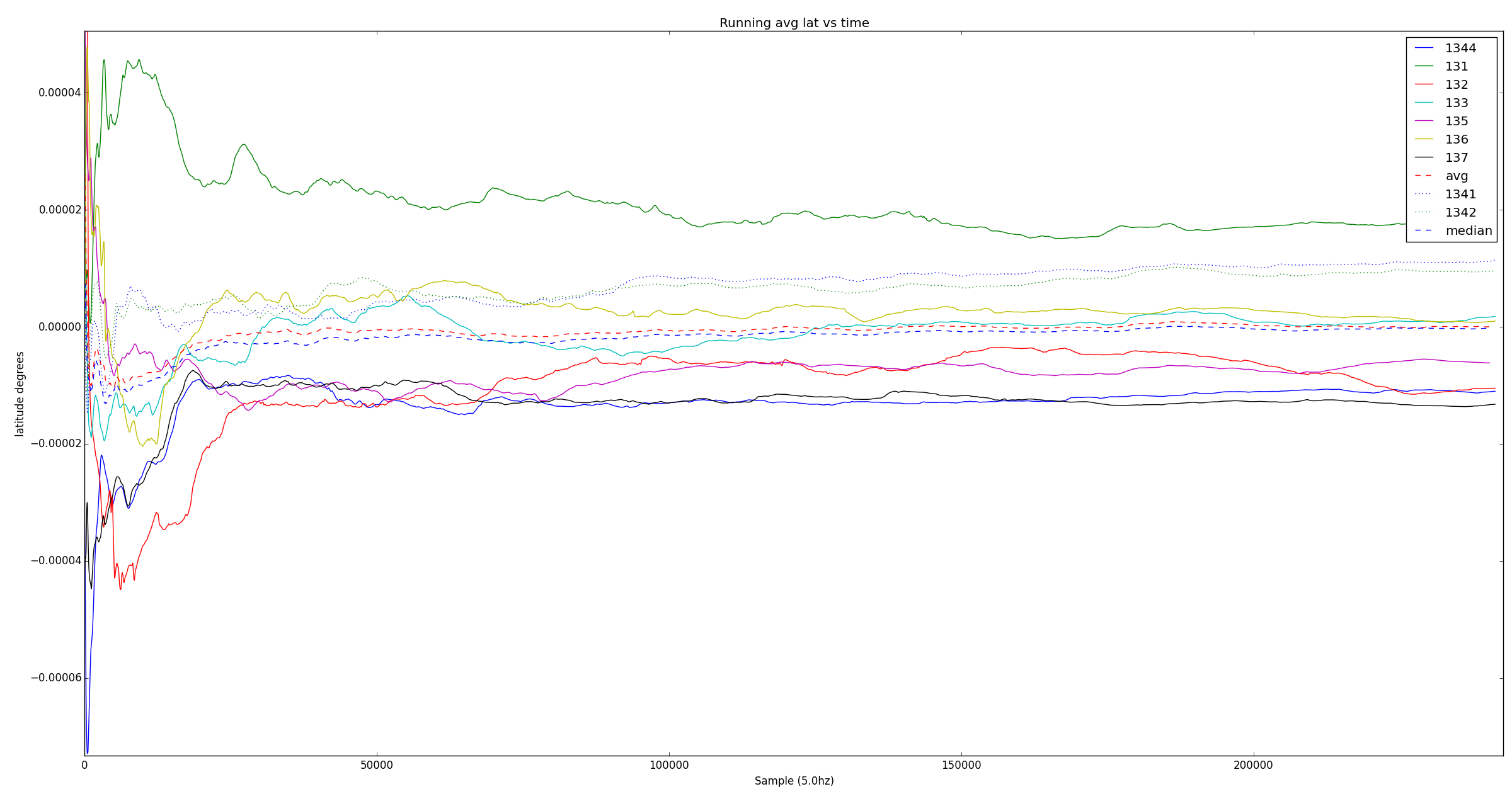
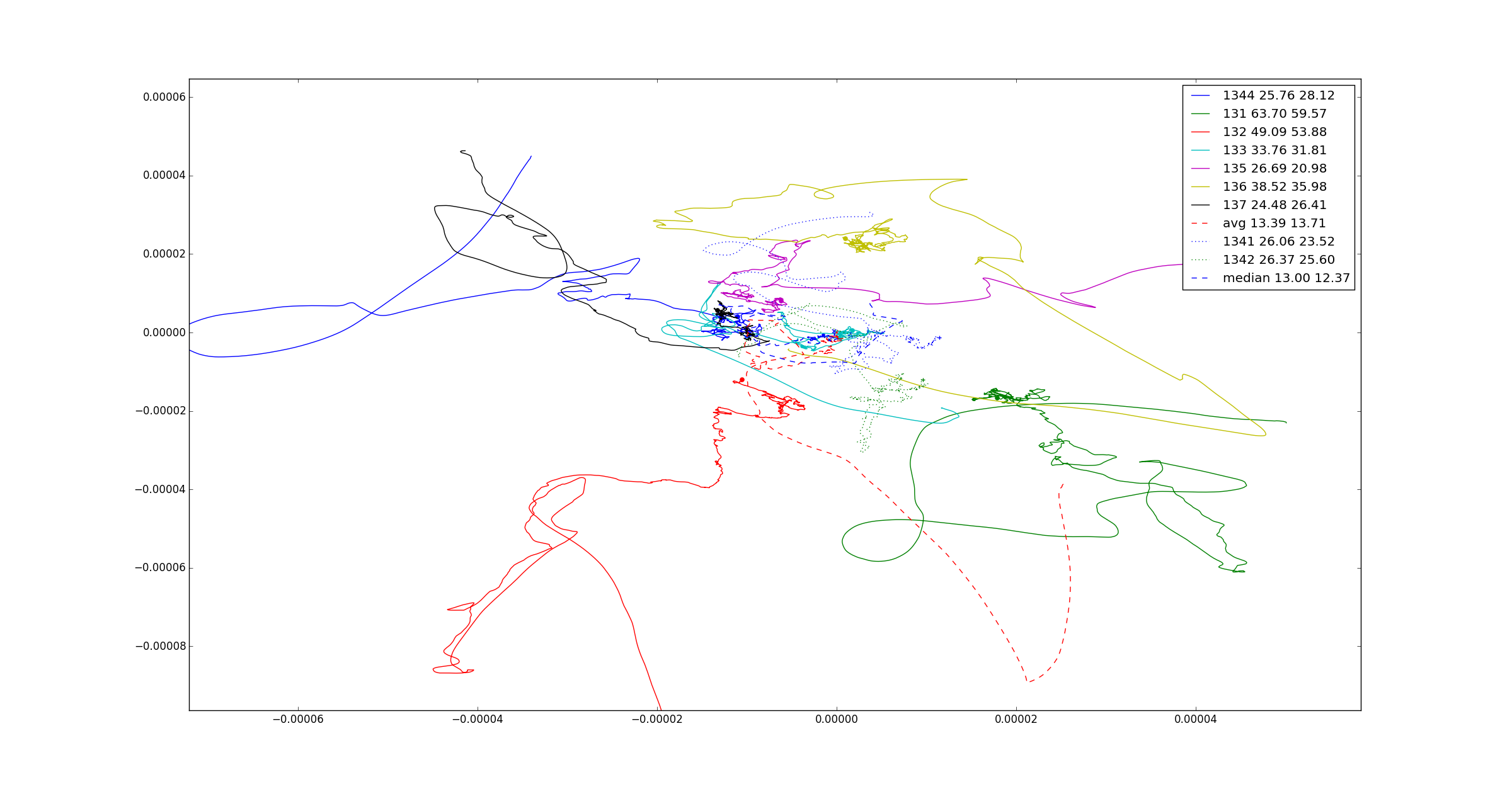
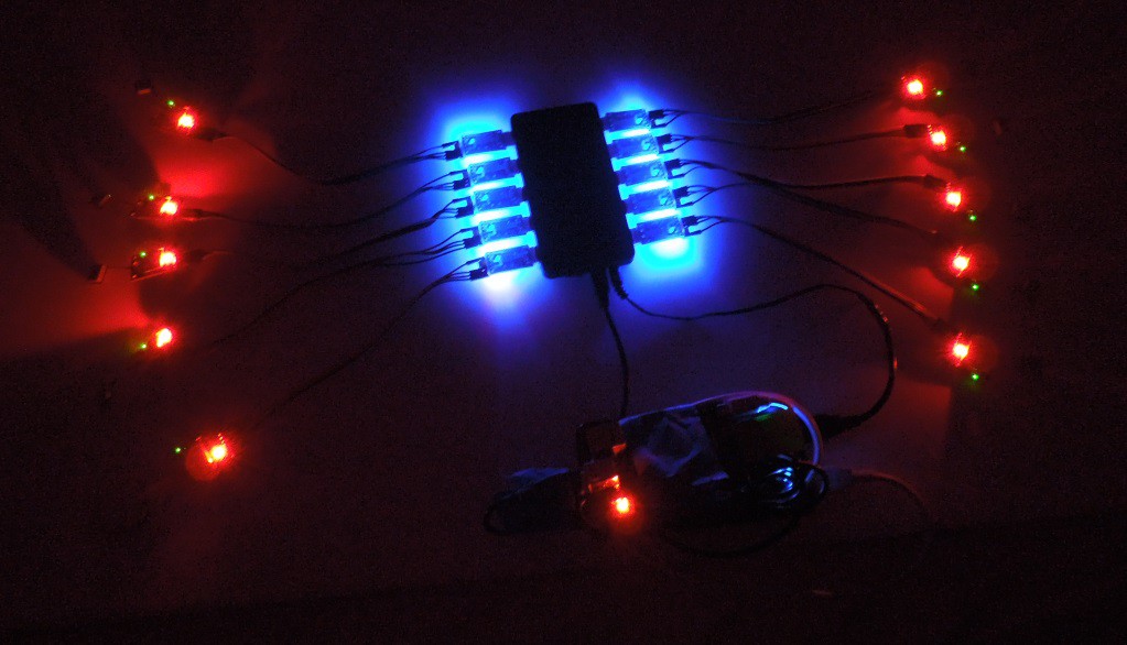
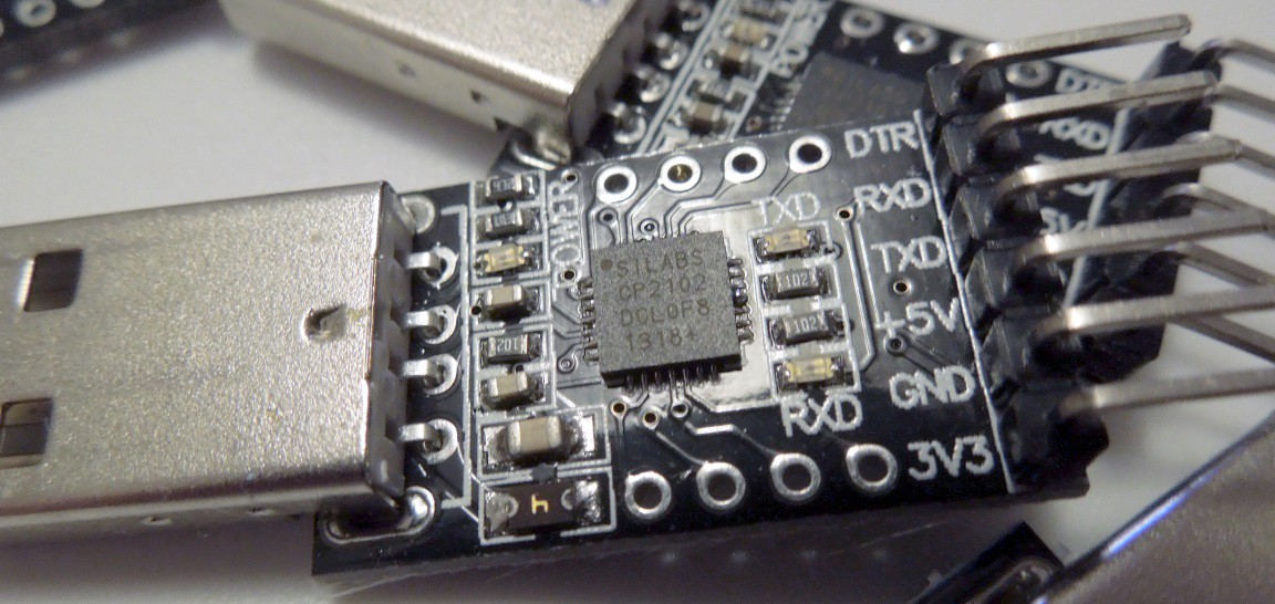
- Test 10 GPS modules using 10 USB-serial converters on a 10-port hub to check that the errors are uncorrelated. (Done, mostly uncorrelated)
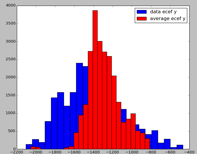
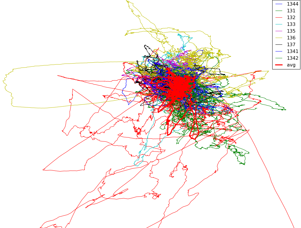
- Compare the error of the averaged position to the error of each individual module. (Done, averaged is better, some modules are performing much better than others for unknown reasons)
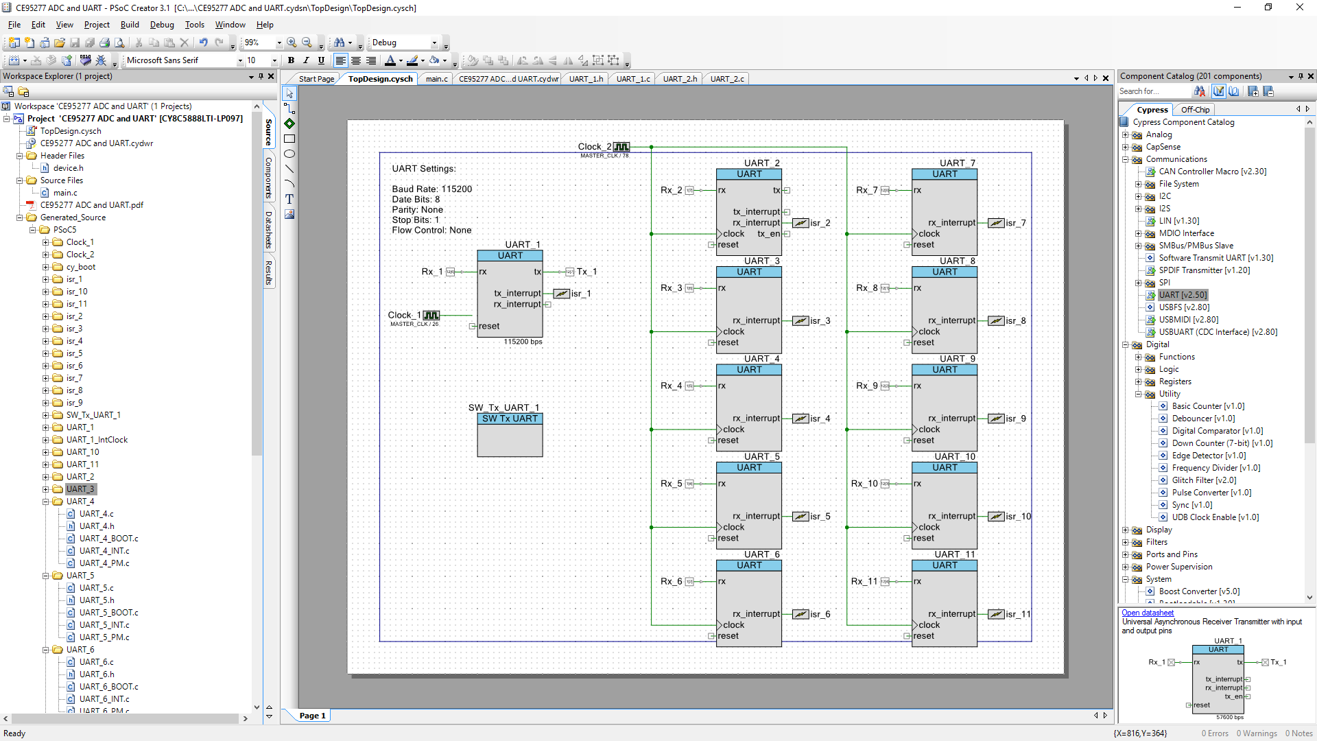
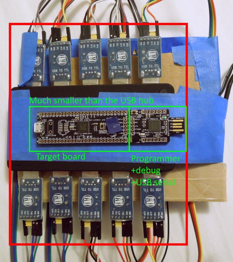
- Make it smaller – Use a PSoC5 to replace the 10 USB-serial modules and USB hub. (In progress - PSoC code works)
- Test it outside and in motion
- Do all calculation in real time on the PsoC and output the position like a single GPS with better accuracy while minimizing latency
License
The python code for analysis is my own work but I haven't decided on a license yet. It requires Python (Python Software Foundation ("PSF") license), SciPy (BSD), and Matplotlib (BSD compatible based on PSF license)
The PSOC code was based on the Cypress PsoC ADC and UART example which permits use of the code in conjunction with a Cypress integrated circuit.

 Randy Elwin
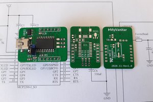
 hesam.moshiri
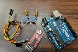
 Sagar 001
 David
David
Did you attempt averaging all of the points from a single receiver and comparing it to the average of all of the points of all of the receivers? I am just curious if just the act of averaging gives you a tighter grouping. This is similar to smoothing input data from sensors that report to quickly. Like accelorometers.