Siggi
SiggiThe Protocol
The communication channel uses the same signal as the old EIB system. The data format is similar to EIB. You can find some more informations about the successor KNX here in this wikipedia article.
Why using wires and not RF?
Using wires have some advantages:
- No batteries required for the switches as all nodes are powered over the wiring,
- no interference with other RF systems
But has one disadvantage: It's necessary to have an additional wiring in the house electrics. The best way to build it in is during building or renewing phases.
In a later phase an interface with RF is planned.
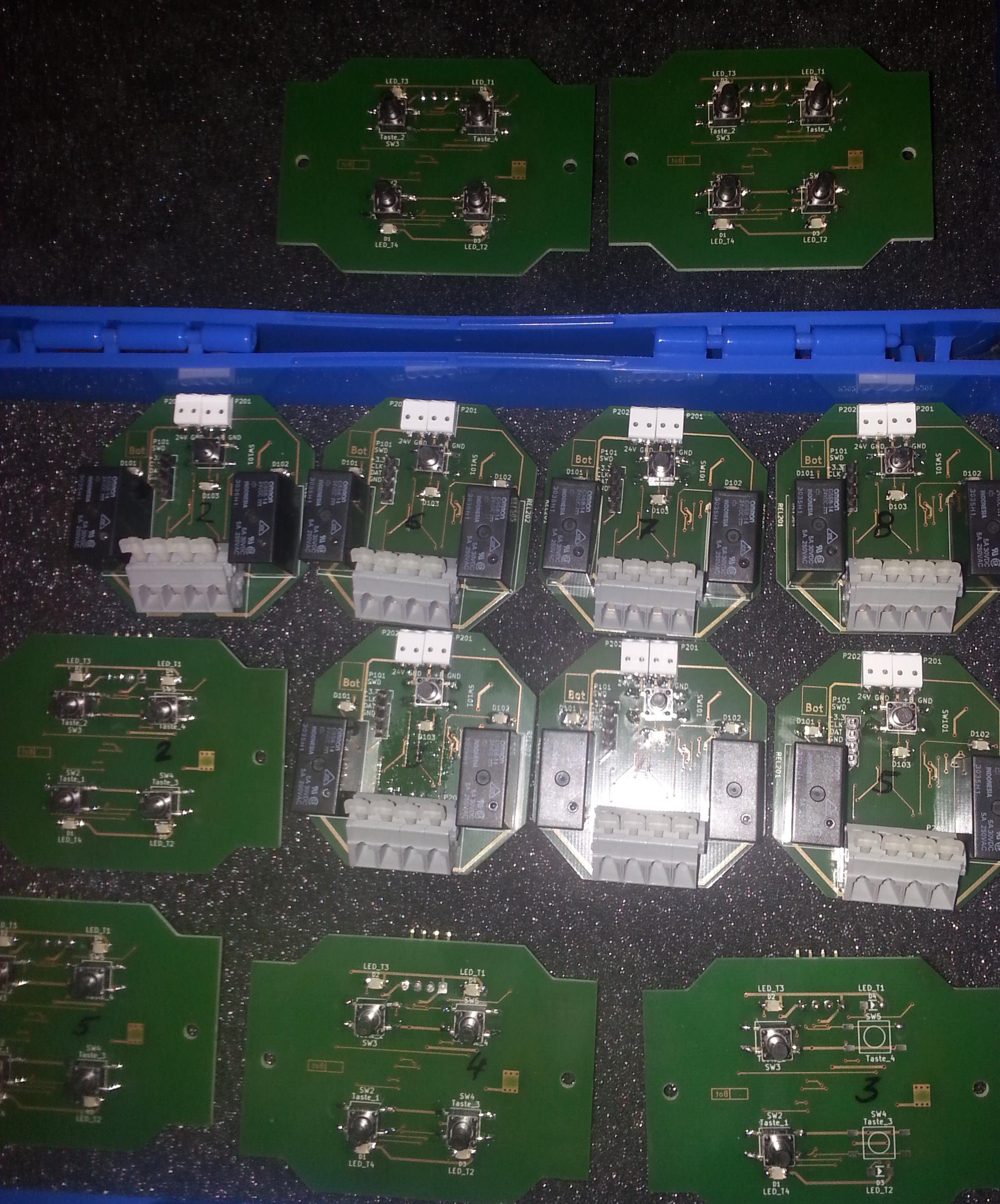
The Modules
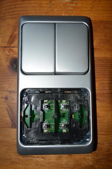
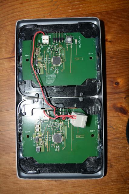
The Switch Module
This module provides four switches, which can send up to 16 different commands. The commands can be grouped, so that one switch can send e.g. three different commands.
The height of the module allow it to mount it directly on the wall.
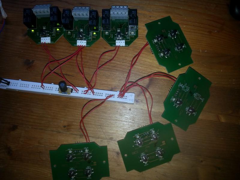
The Relay Module
Containing two relays, this module can work as
- a switch for the lights or
- a relais for blind motors.
It has the cappabiltiy to react on up to 16 different commands. These can be split between the relays as needed.
The size of the module allow a mounting inside a flush socket, even below the switch module.
The Power Supply
As the data are modulated on the power supply voltage, a special power supply is needed. The nominal supply voltage for the system is 24V.
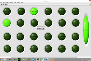
The power supply integrates also a configuration and programming tool.

 Saabman
 Quinn
Quinn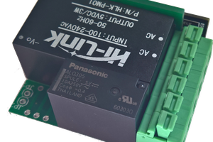
 Roger Zander