 Kevin Kadooka
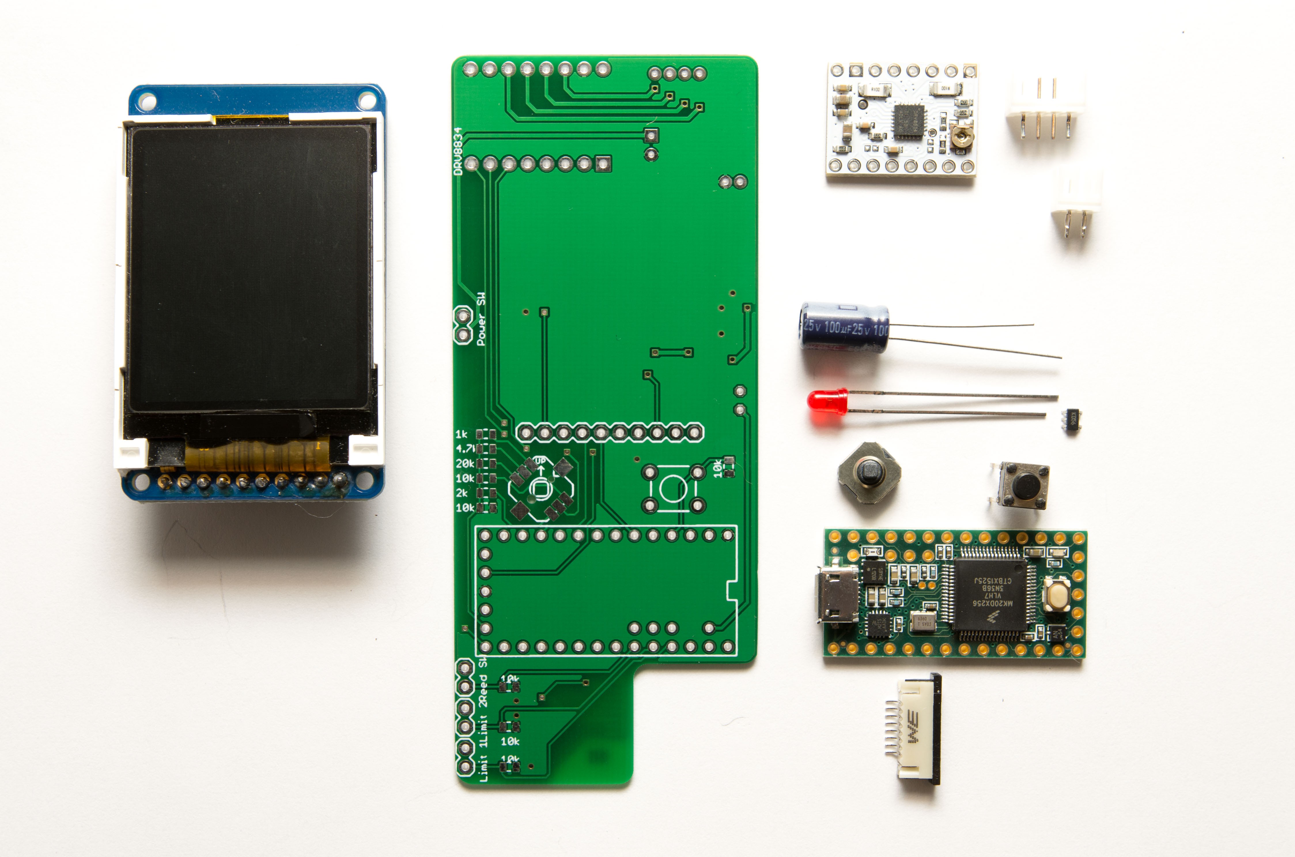
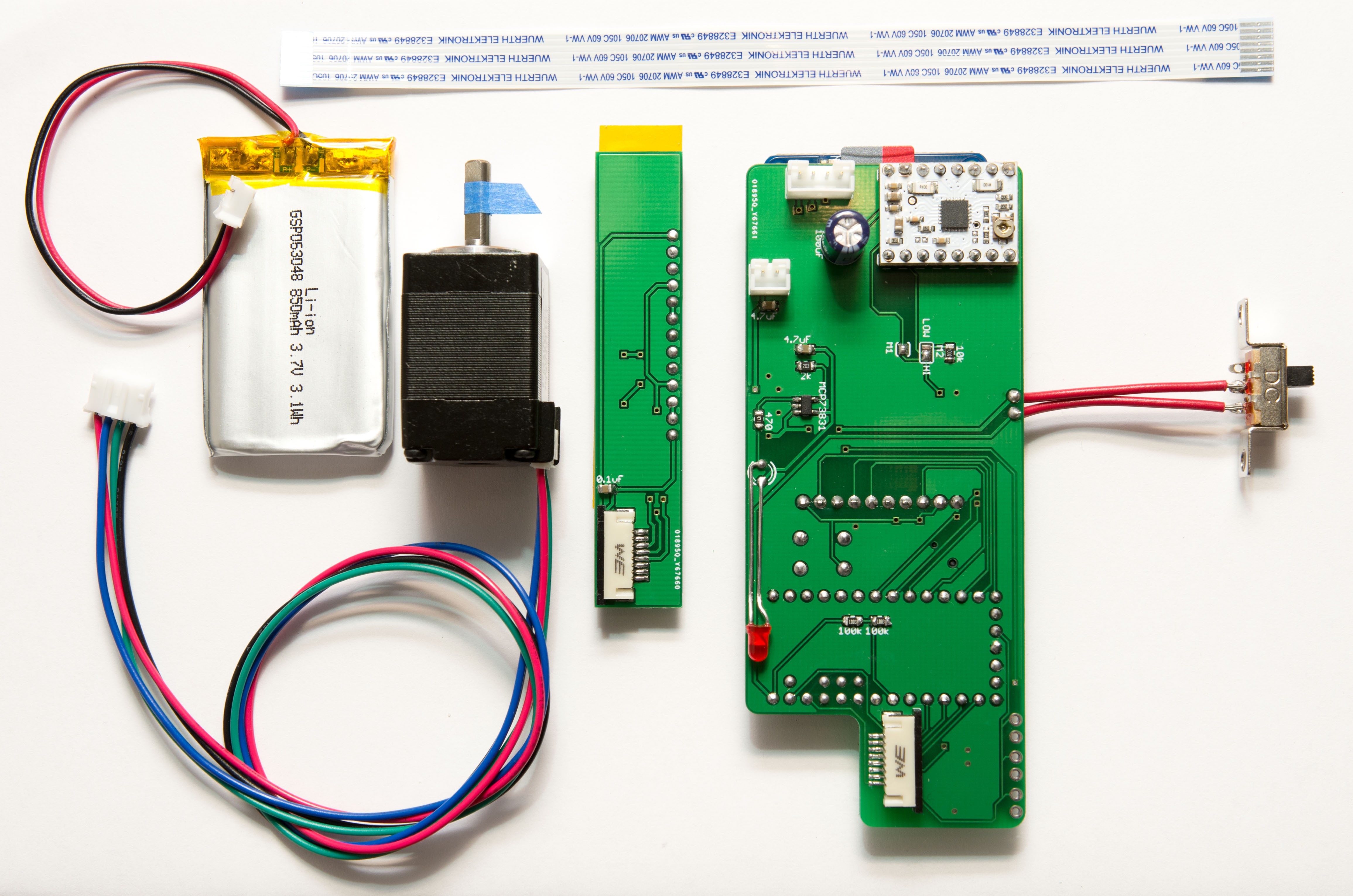
The last SMD components took a little longer than I had hoped to come in (this past Monday). With that order in, I had all the parts to start populating the Main PCB, constituent parts shown below (SMD resistors omitted).
- Adafruit 1.8" TFT (160 x 128 px)
- Pololu DRV8834 Stepper driver
- 5-way joystick (Sparkfun COM-10063), 6 x 6 x 5mm tact
- Teensy 3.1
- 8-contact FFC connector, 1mm pitch (Wurth)
- Red LED
- MCB73831 LiPo charge IC
- 2P, 4P JST-PH male receptacles
- Assorted 0805 SMD resistors (not shown)
All soldered up, minus the limit switches, which will have to be added later. I'm not a big fan of soldering SMD stuff, even the 0805's. Especially after a cup of coffee in the morning.
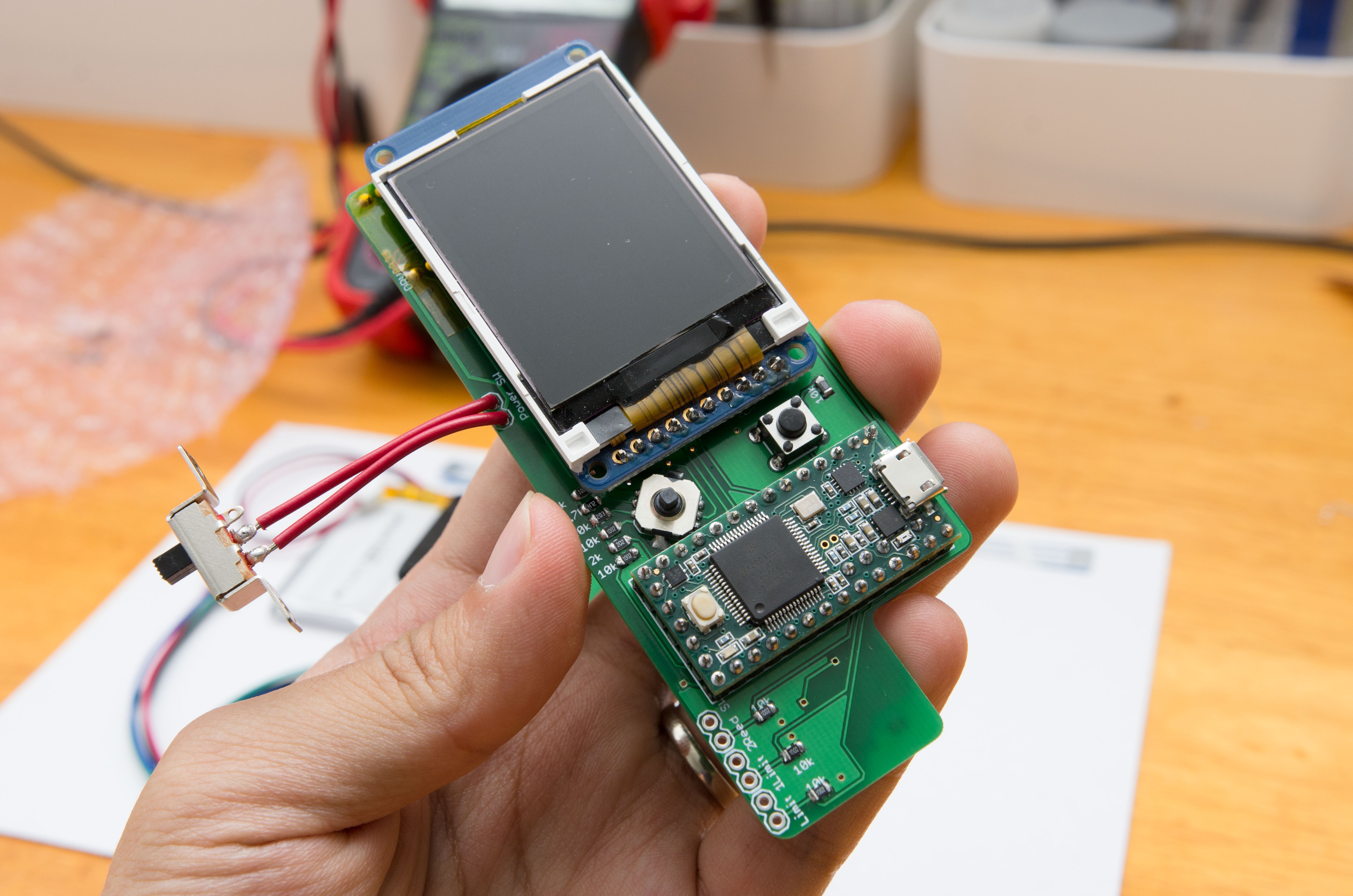
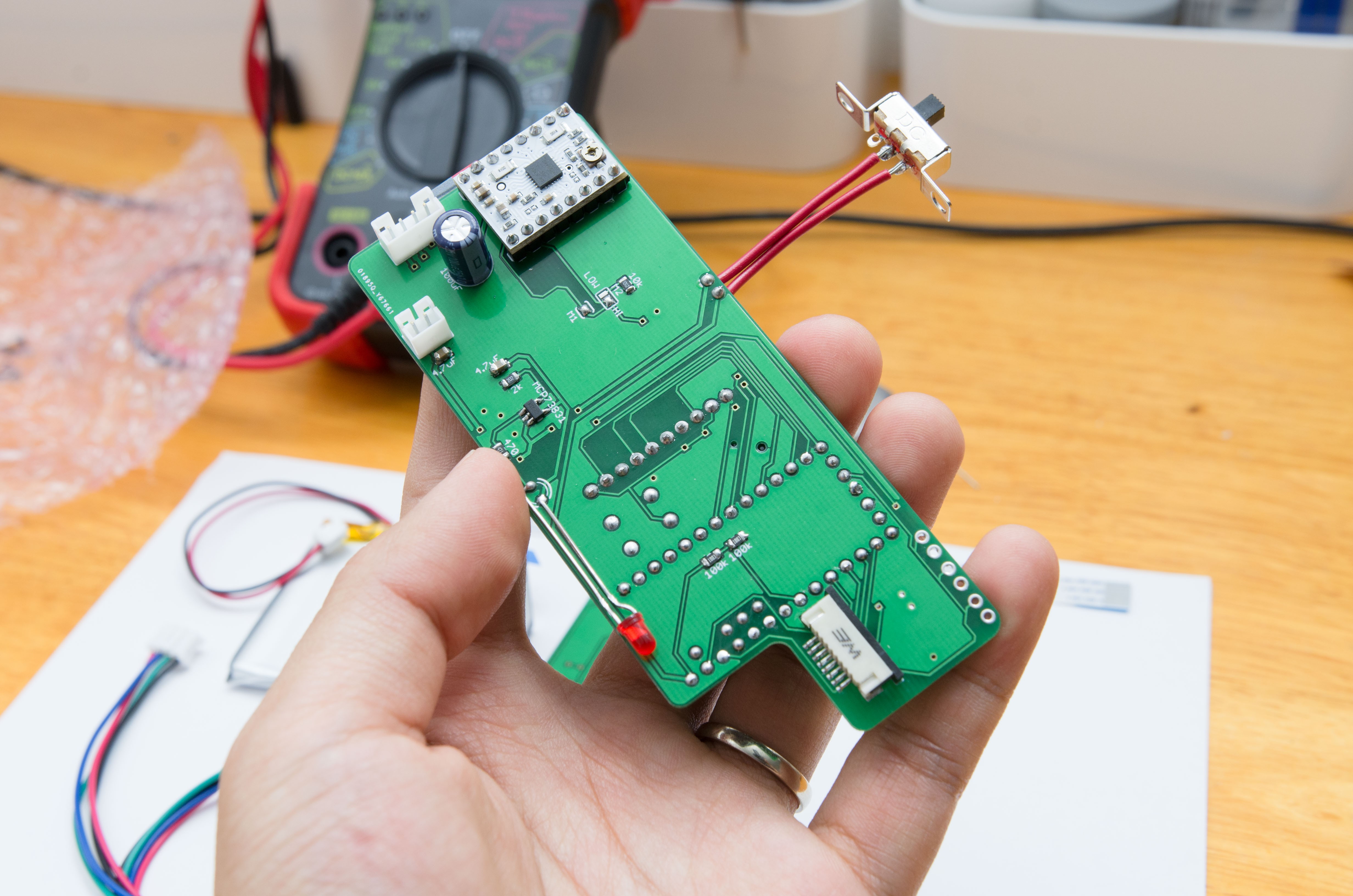
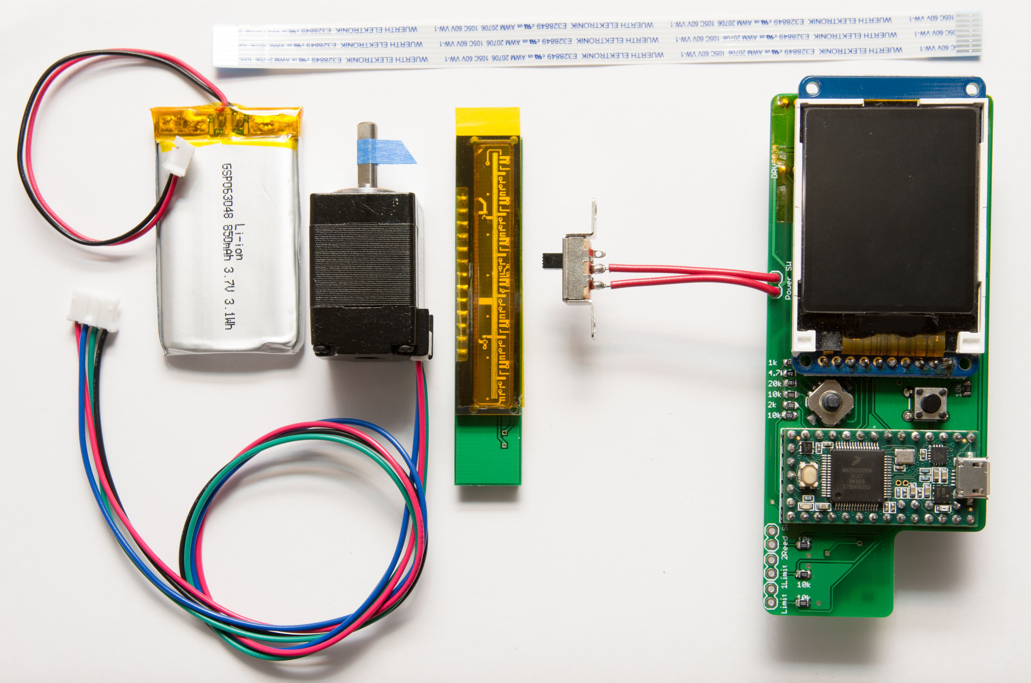
Here's all of the electronic bits and pieces. I put a piece of Kapton tape on the image sensor to avoid it getting dirty and scratched for now.
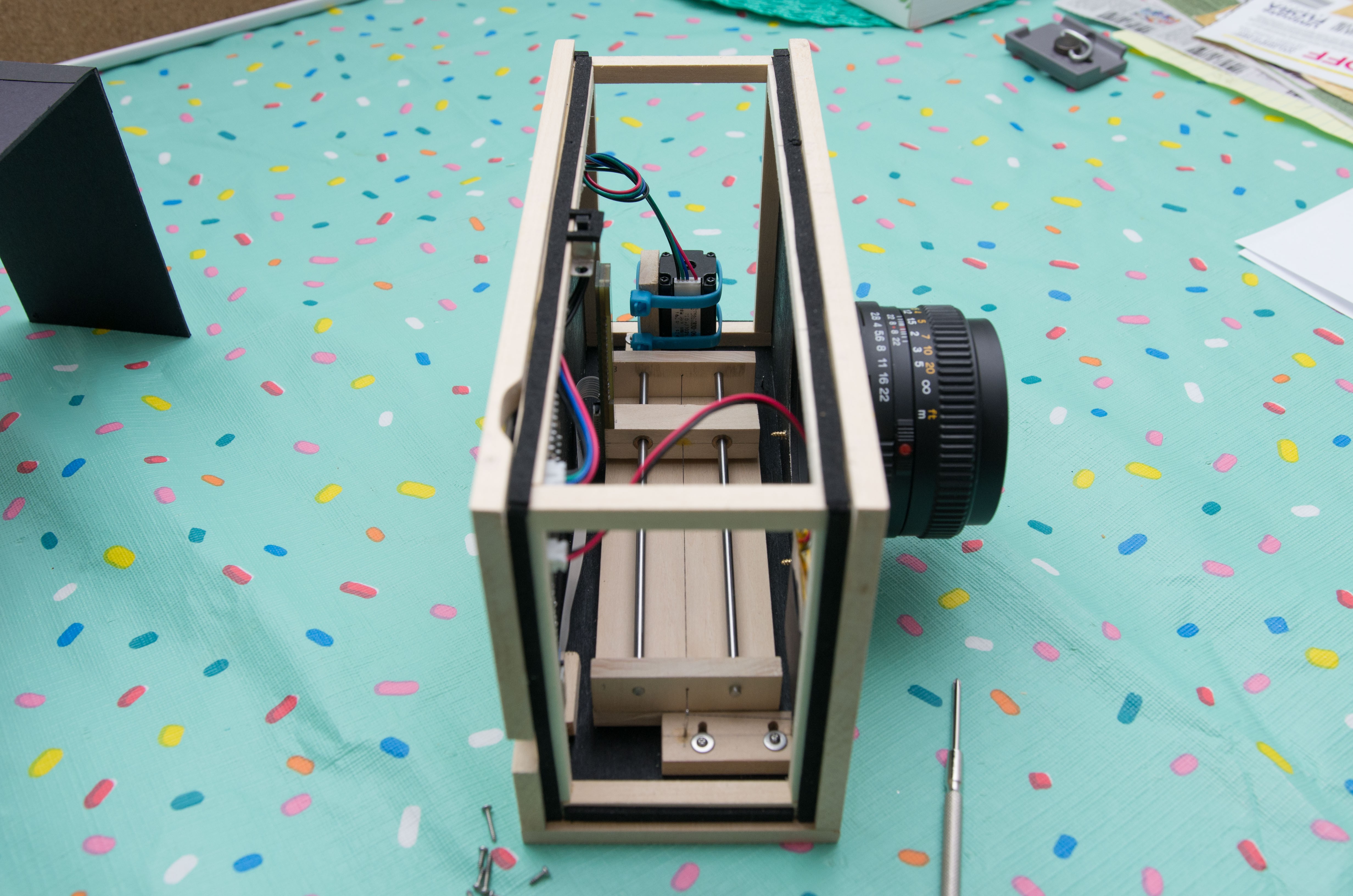
At this point I considered ordering the 3D printed parts - but then I looked at the total cost, and again at my wallet. Nope. Considering my nonexistent budget, I instead went to the university book store, and picked up several planks of basswood ($20) and decided to use parts on hand as much as possible. I had a few 1/8" steel shafts and brass bushings from previous projects, and those worked just fine to make a linear stage. It wobbles a bit, but it will do.
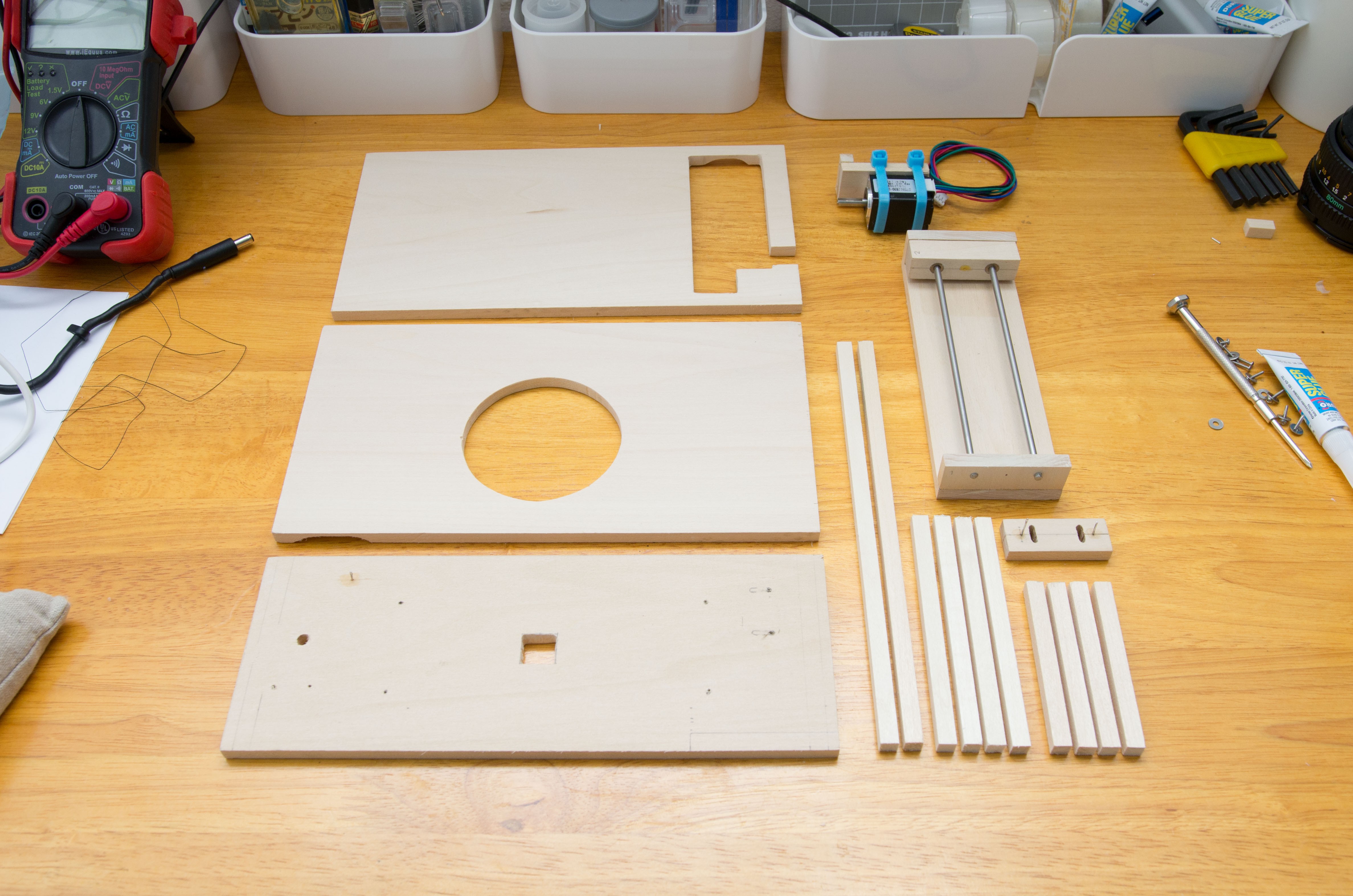
This part I'm pretty proud of! The original plan (for the 3D printed version, which may be a ways off now) was to use a belt and pulleys to drive the linear stage. But those cost $$$ and would take a week or so to come in - so instead I'm using silamide thread (waxed nylon filament used by beaders - it's resilient and pretty slippery, not to mention cheap!) run through the eyes of several sewing needles. Each end is attached to the stepper shaft so that they wind or unwind, making a push-pull sort of arrangement. Tension can be adjusted by the block to the lower left, increasing or decreasing the track of the string.
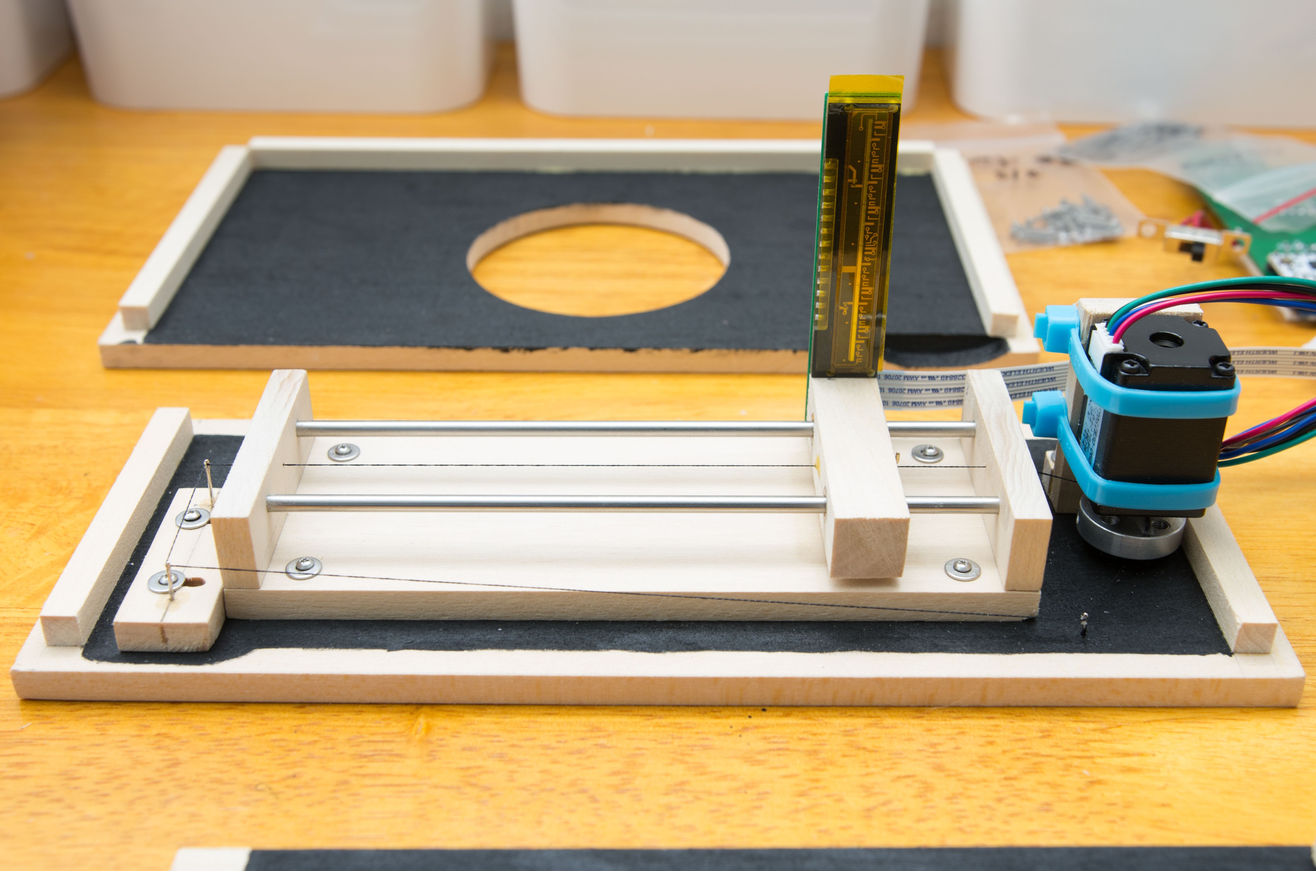
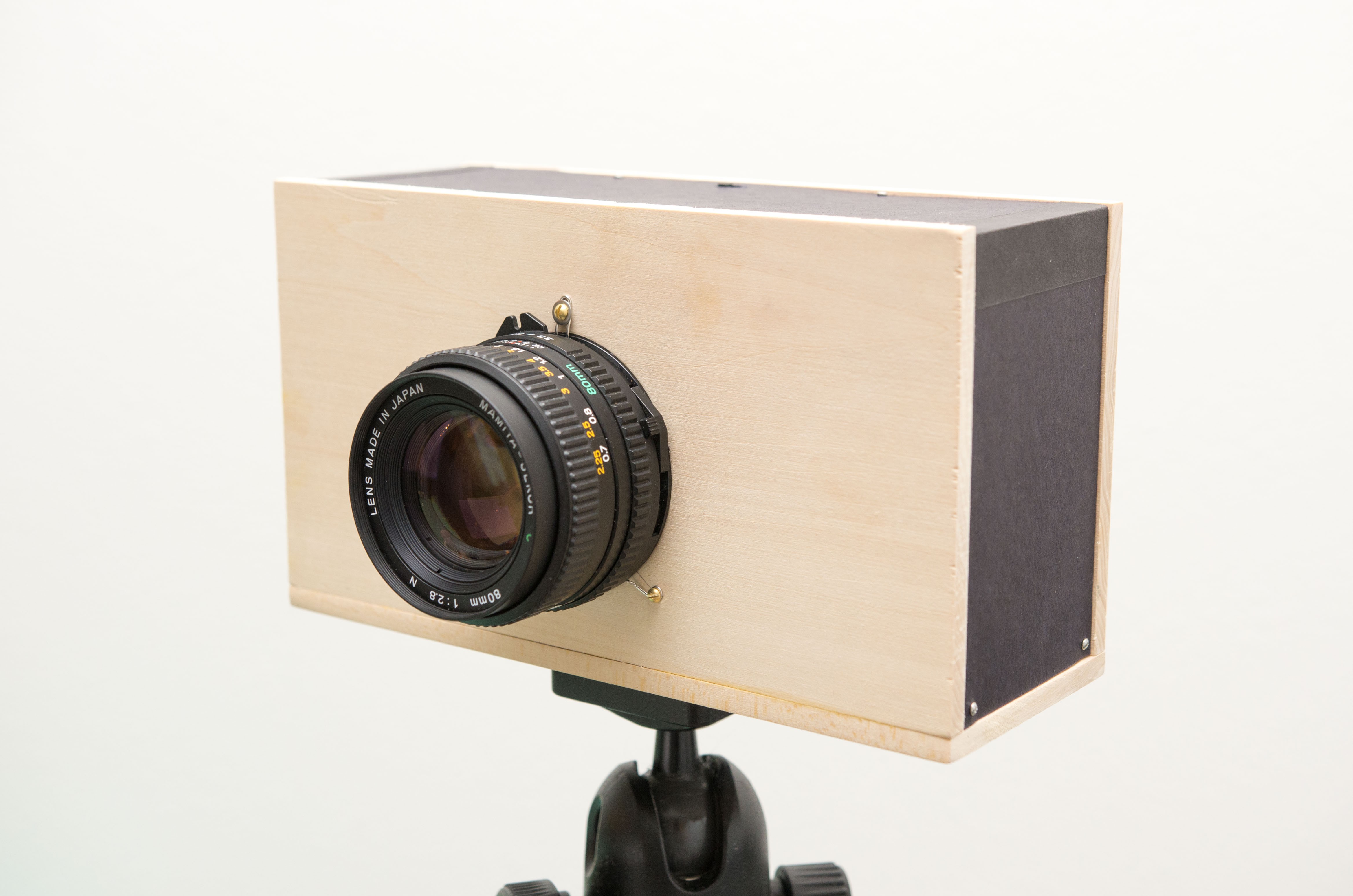
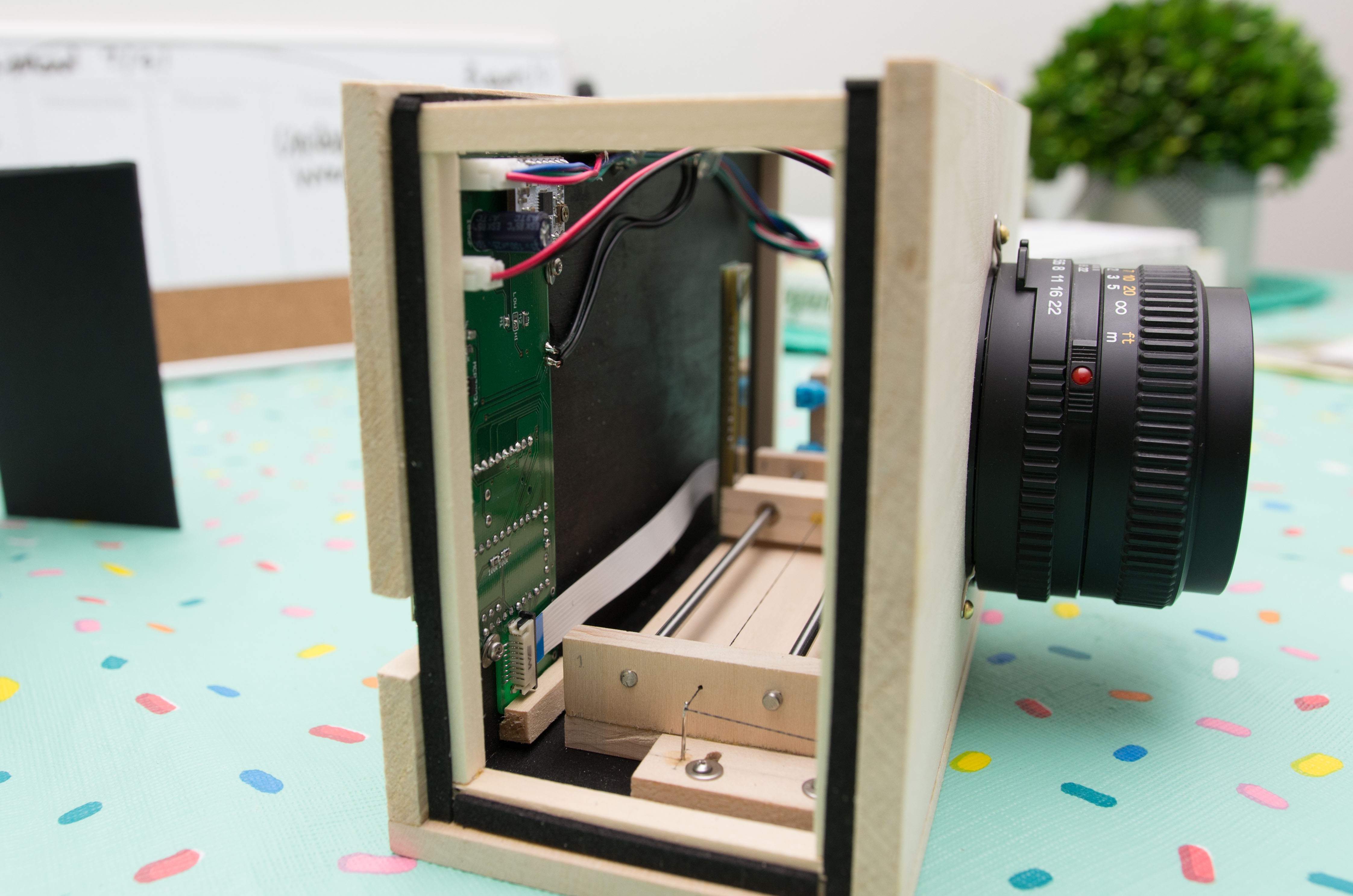
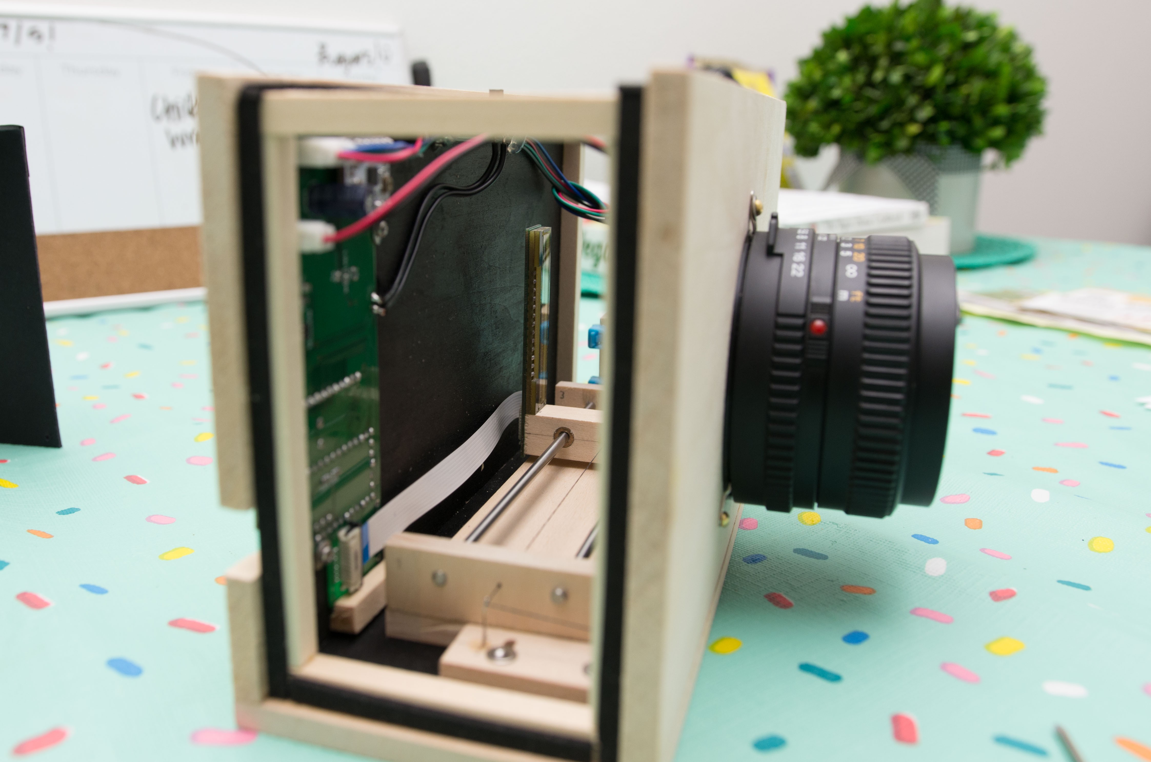
I'm skipping a few steps here - just a lot of cursing and gluing things together when they weren't supposed to be - but here's the finished first prototype. Yeah, it's pretty chunky, and missing a few of the key functionalities of the final product (namely the ground glass viewing screen). But it works! For now.
The Main PCB is exposed, as I couldn't think of a good way to cover it up and still access the buttons and USB port without routing (something I routinely try to avoid). Works for now, but later I would like to put a piece of clear acrylic over it to protect things.

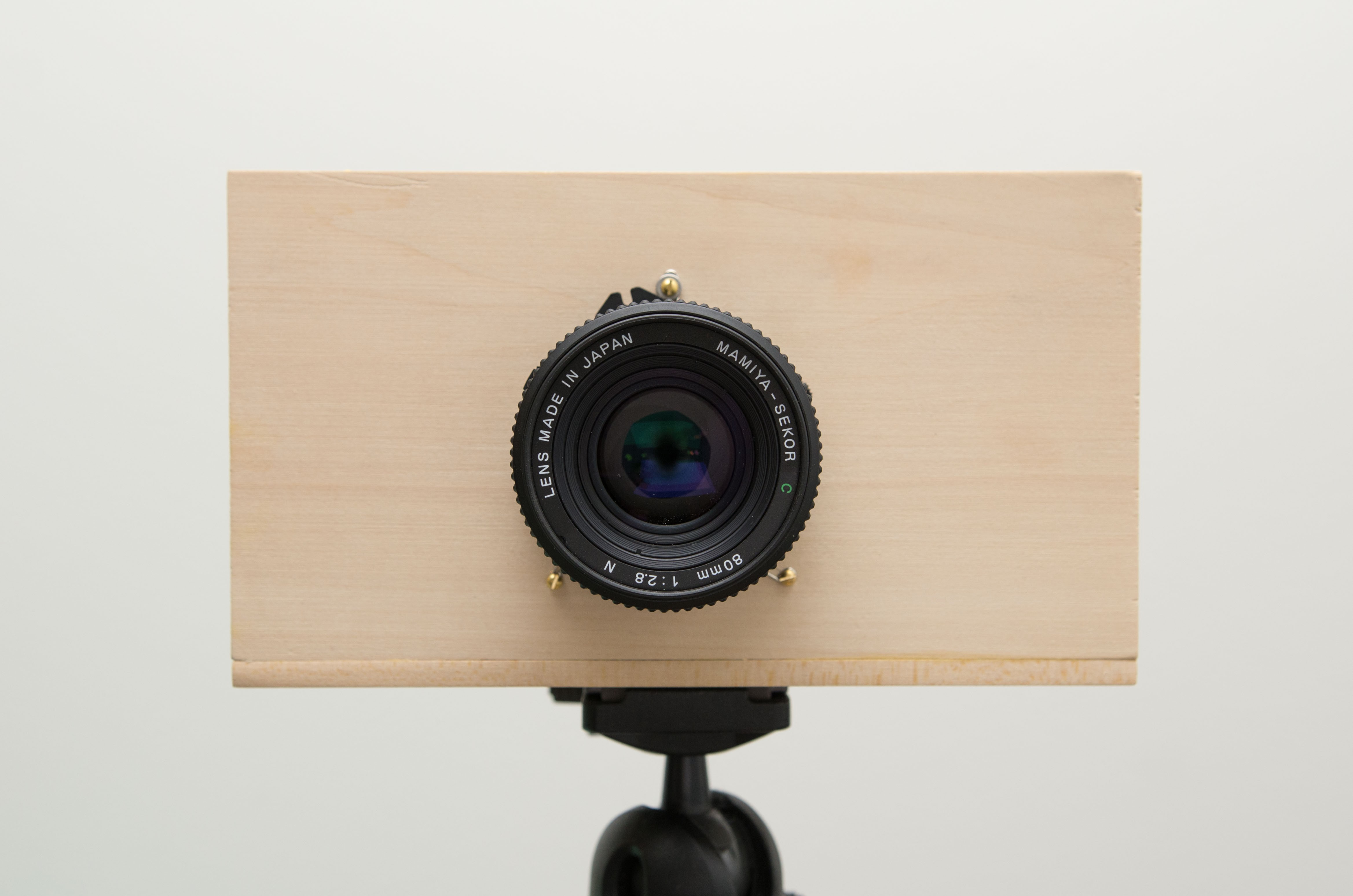
The next photos show how chunky the darned thing is - about 75 x 120 x 210 mm (without lens). The 3D printed one would have been a lot more svelte, but you get what you pay for, right?
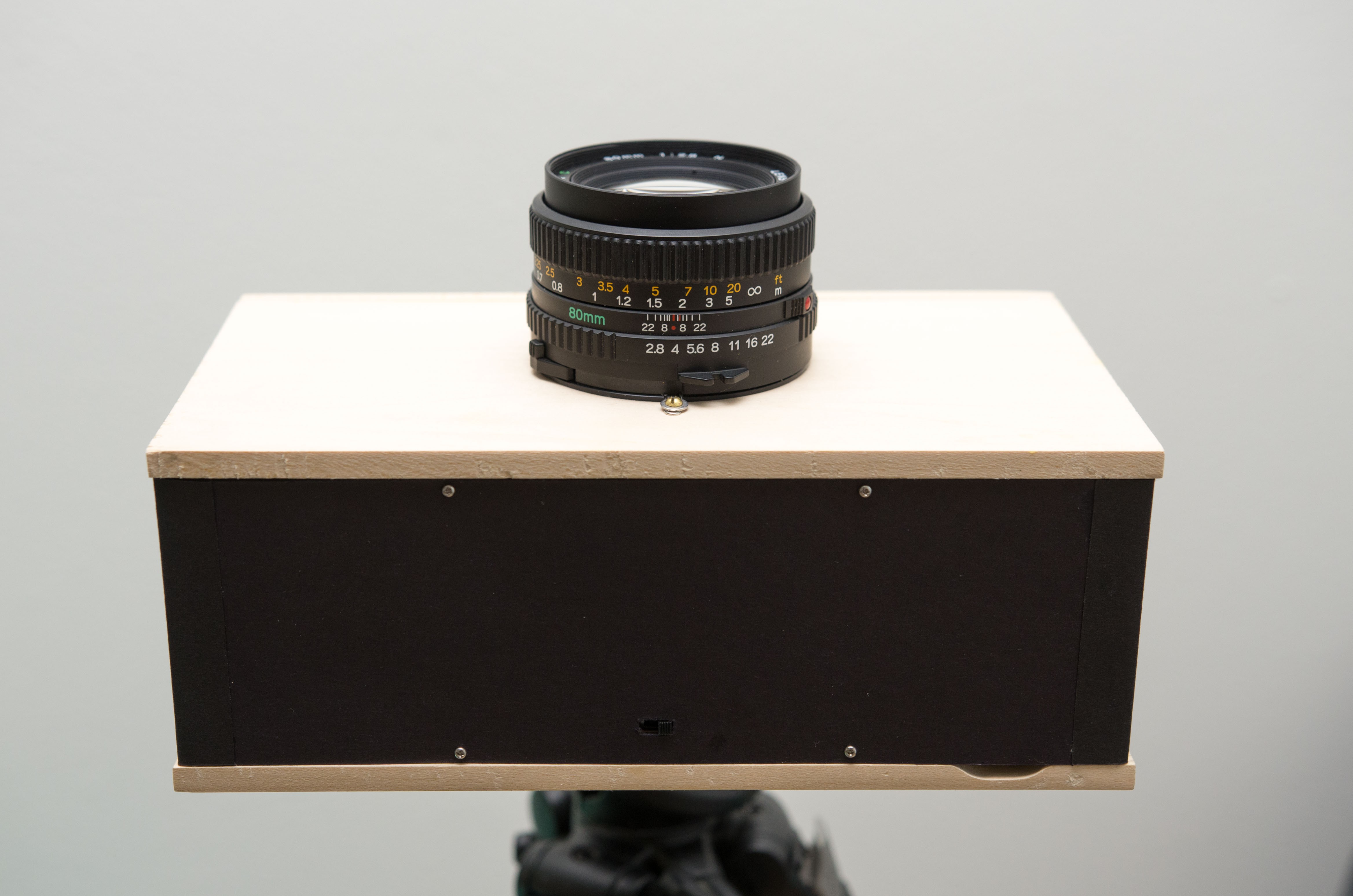 Pop the top (just some black card stock) and you'll see that it's just a basswood skeleton with the electrical bits tacked on inside. A bit of open-cell foam is used to seal out extraneous light and improve contrast.
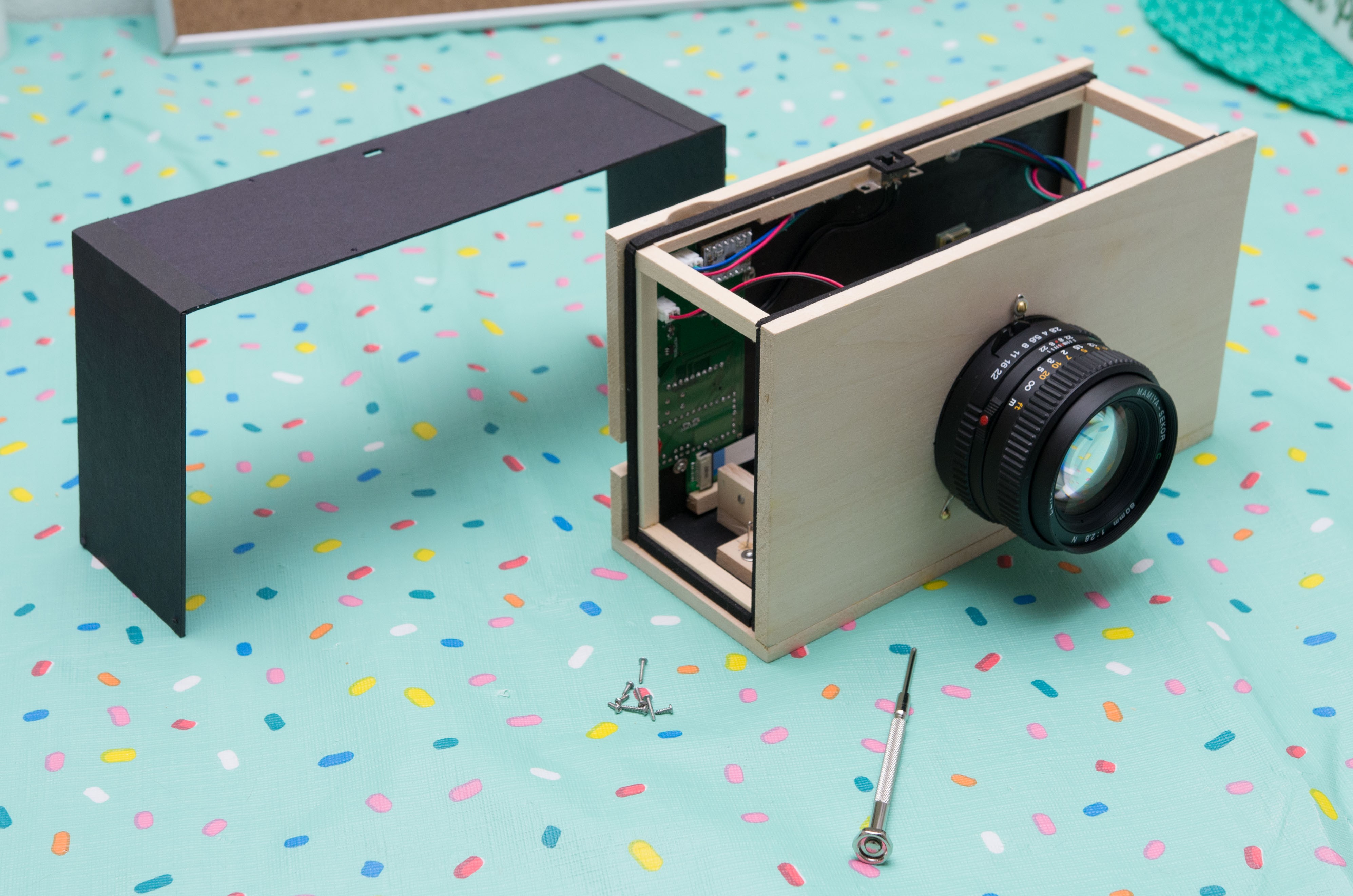
I left a LOT of room inside to avoid backing myself into a corner. That explains why it's so big and bulky.
The electrical components are just held in by screws or tacked on by some Elmer's glue-all, so they can be easily recycled. The lens is held on by screws and bent-up paper clips, but hey, it works.
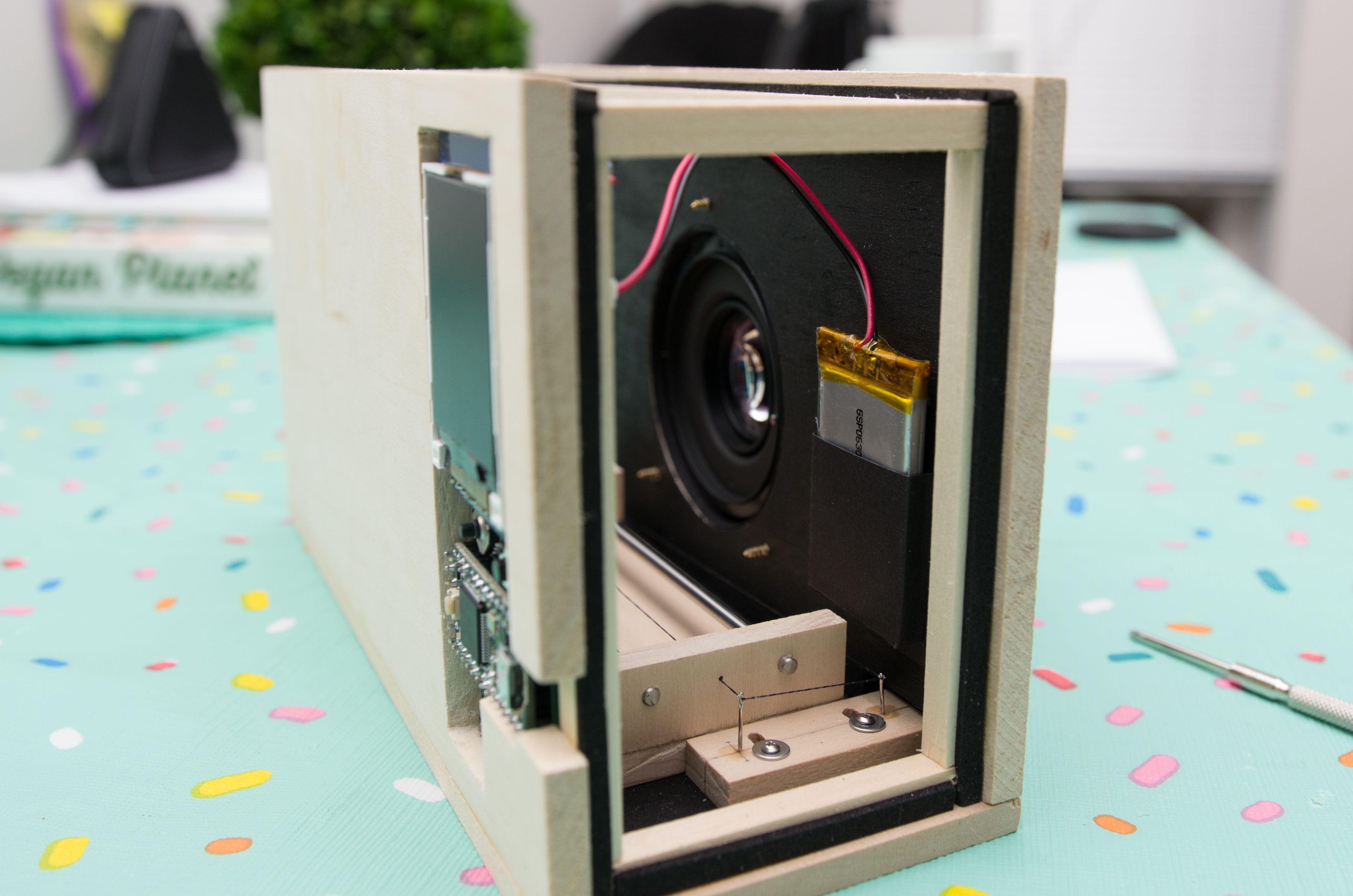
Last but not least, there's a small pocket for the LiPo.
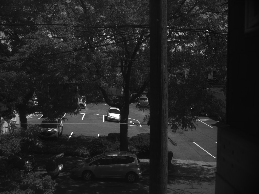
Finally - here are some photos straight out of the camera (well, imported to Photoshop as 16-bit PGM, and exported as JPEGs - but absolutely nothing changed in between).
From my apartment window (f/8, 1/500s integration time)
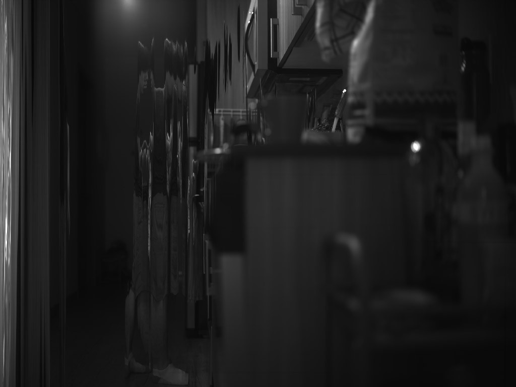
Making dinner (f/2.8, 1/15s integration time)
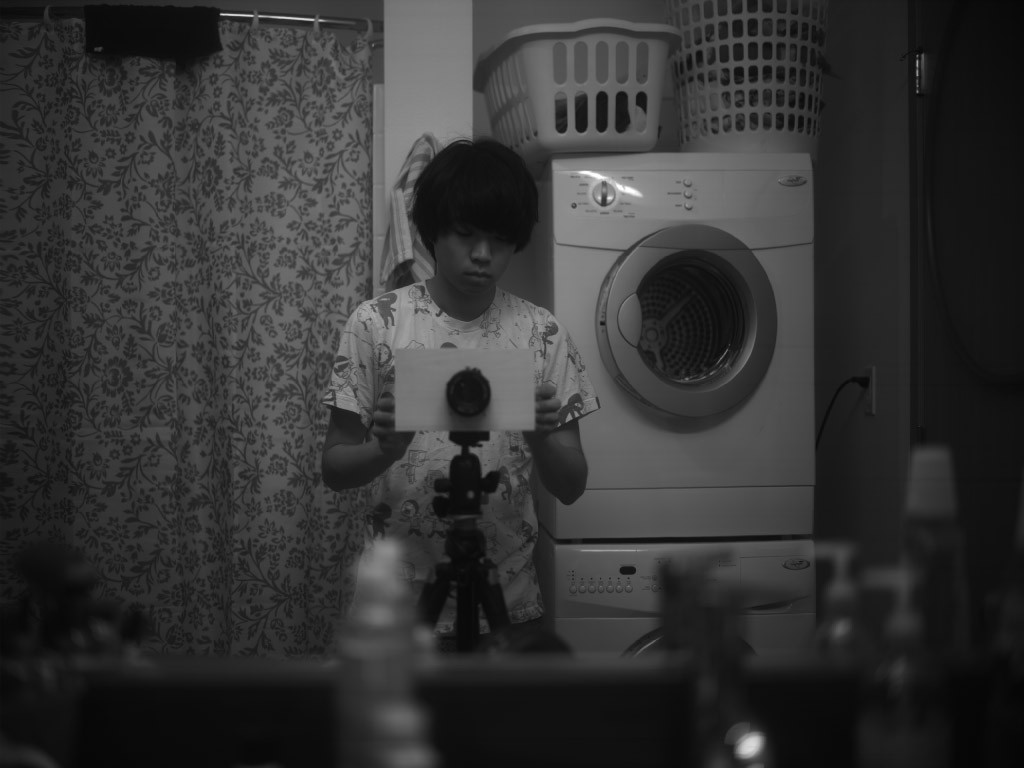
A rare selfie (f/2.8, 1/60s integration time) - this one has some levels adjustments in PS
Contrast looks way, way better now that there are fewer light leaks, but that is to be expected. I'm happy with the dynamic range and sharpness for now.
Still quite a few things to improve - like the lack of an easy way to focus and compose, and there are quite a few bugs to squash with the firmware.
Discussions
Become a Hackaday.io Member
Create an account to leave a comment. Already have an account? Log In.
Great question! Initially I was just using scale focus and guess-and-check, which was OK considering that the scan time is usually ~10 seconds. But the eventual goal will be to have a piece of ground glass that swings into position for viewing.
For now I am using a pseudo-CDAF method where I continuously scan one line from the center of the frame, and push the central part (160 x 1 px) to the display. The image data is displayed as a bar graph - high contrast and correct focus shows up as sharp peaks and valleys. So far I have found that this works OK though it is not trivial to use.
I'm working on some code that will continuously scan the central 128 x 128 px and push to the display, and use focus peaking to highlight in-focus areas. Will be slower than the line-scan method I'm using now, but hopefully more illustrative.
They are just paper clips and screws holding the lens flange against the box ;)
Are you sure? yes | no
The one-line scan focus is something like elm-chan did here? http://elm-chan.org/works/lcam/report.html
He is displaying both values as well as first derivative, showing peaks/walleys even more clearly.
How do you swing the piece of glass into the exact position where the scan-head is doing scans? I assume tuning the position of glass and scan-head pass-through plane is going to be non-trivial, as well as keeping the configuration stable against temperature changes or vibrations, but perhaps I'm a bit too much pessimistic about the required precision - honestly I have no practical experience here, just great interest in scanner cameras.
I assume the glass method will work when there isn't too much light around, otherwise you have to cover yourself
And, perhaps I overlooked something, but how do you store the scanned pictures? Is there any kind of mass storage in the camera, or you are streaming it through USB?
Are you sure? yes | no
Interesting link, I haven't seen it before! And yes, that's the same principle. I haven't yet gotten to showing the gradient yet, but I hope to do so in the future.
The glass will have to swing or translate into position, and will have to be calibrated every so often. I would say the required precision is on the order of a couple of hundred microns, which in my experience is doable.
Ground glass works OK even in strong light, as long as there is a shade around it. The bright lens (f/2.8) should also help. A Fresnel screen would also help to keep the illumination even across the whole frame.
Scanned images are stored as .pgm binary files (openable in PS/GIMP) stored on a micro SD card.
Are you sure? yes | no
Thank you for replies, Will keep an eye on this project, I like the way it develops.
By the way, the whole elm-chan's website is awesome, containing a lot of great projects.
Are you sure? yes | no
Thank you for the tips and feedback! It's much appreciated.
Are you sure? yes | no
Great progress.
I know you are going to reveal more in future project logs - but could you, please, tell me about how are you planning to focus the thing? And how are you doing it now? From what I read, this is just box with lens and relatively low-res display, so focusing is not simple, especially considering scan time.
I can see some metal part with screws mounting the lens in wooden box - what is that?
Are you sure? yes | no