 mosaicmerc
A custom laser cut template permits the direct mounting of TO-220 heat sinks (oversized for extra cooling) to the 4 x small TQFP trigger chips that run hot. Direct screw clamping pressure is achieved via plastic 6-32 hardware mounted on the bottom of the O'scope case aligned to the heat sinks for optimum results. Plastic screws limit the max. pressure that can be applied as a safety vs flexing the multilayer PCB. A 30°C improvement has been measured.
0%
0%
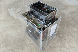
Tektronix TDS 694C Trigger cooling & workaround
This 3Ghz scope suffers trigger chip burn out- this project suggests workarounds/repairs & mods to mitigate this problem.
Become a Hackaday.io member
Already have an account? Log in.
Just one more thing
To make the experience fit your profile, pick a username and tell us what interests you.
Pick an awesome username
hackaday.io/
Your profile's URL: hackaday.io/username. Max 25 alphanumeric characters.
Pick a few interests
Projects that share your interests
People that share your interests
 Roger
Roger
 baaskaas
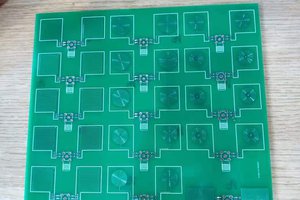
 MG
MG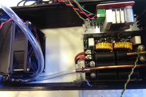
 Costa
Costa