 DTeel
DTeelIll get to this later.
0%
0%
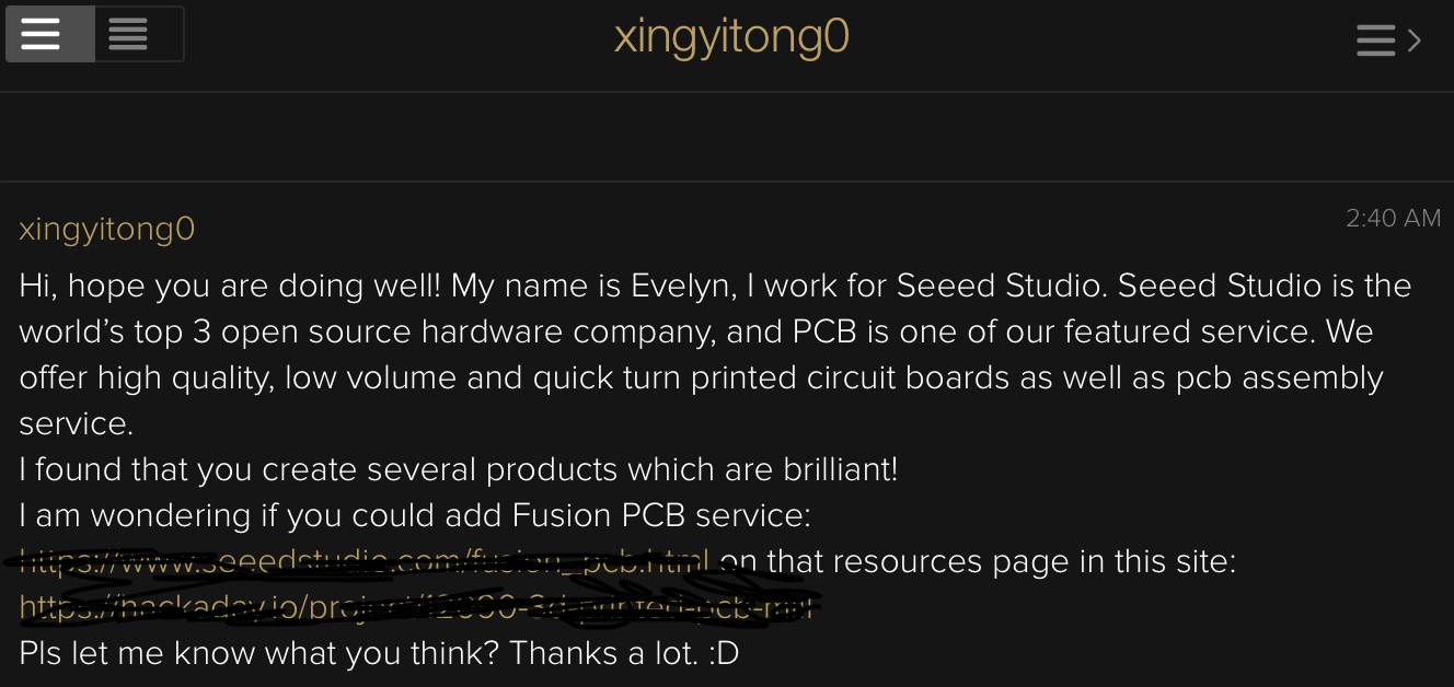
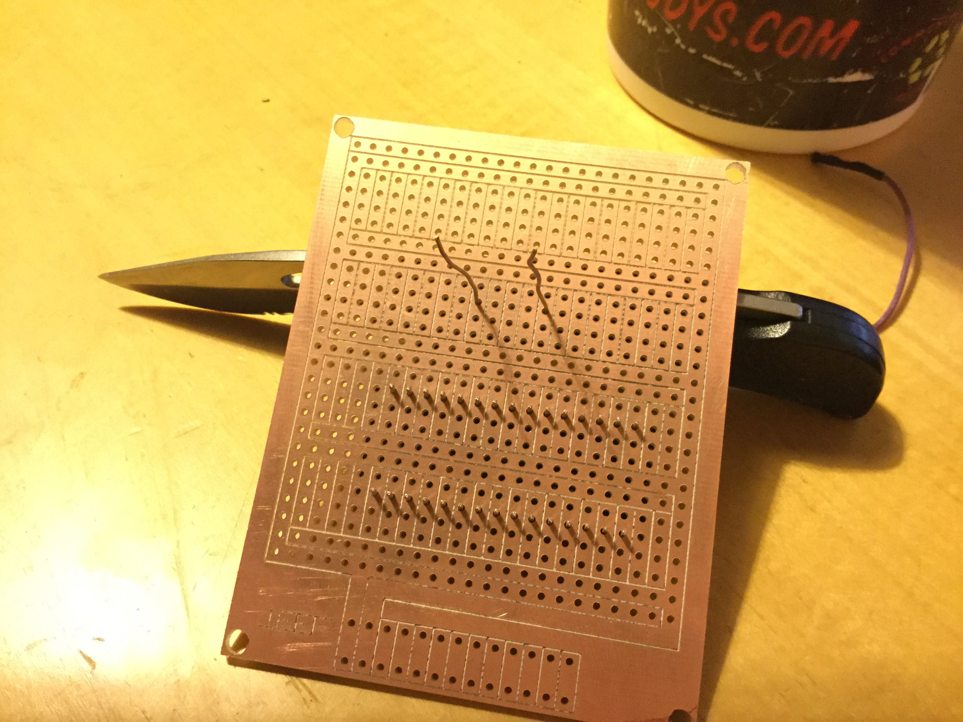
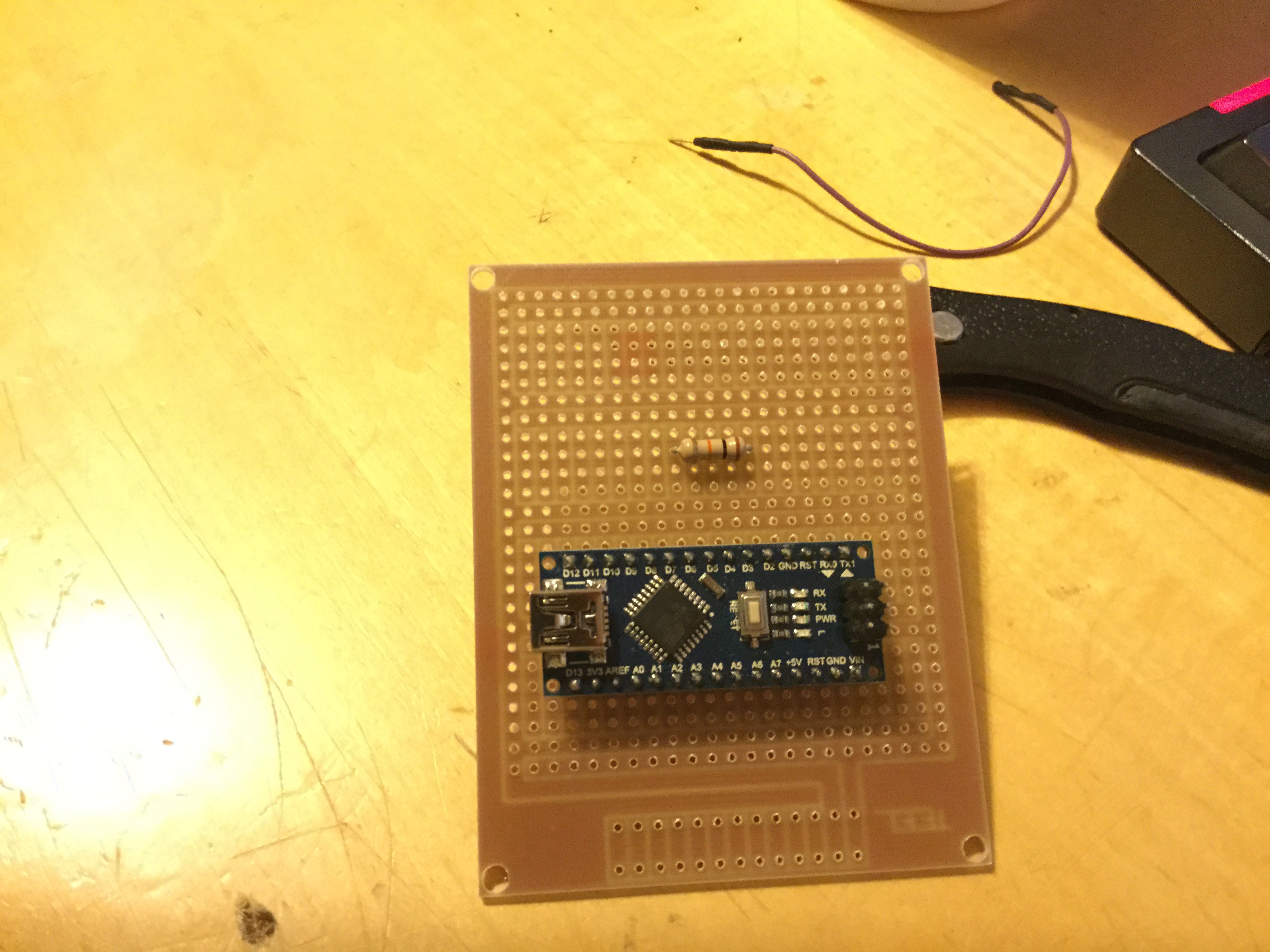
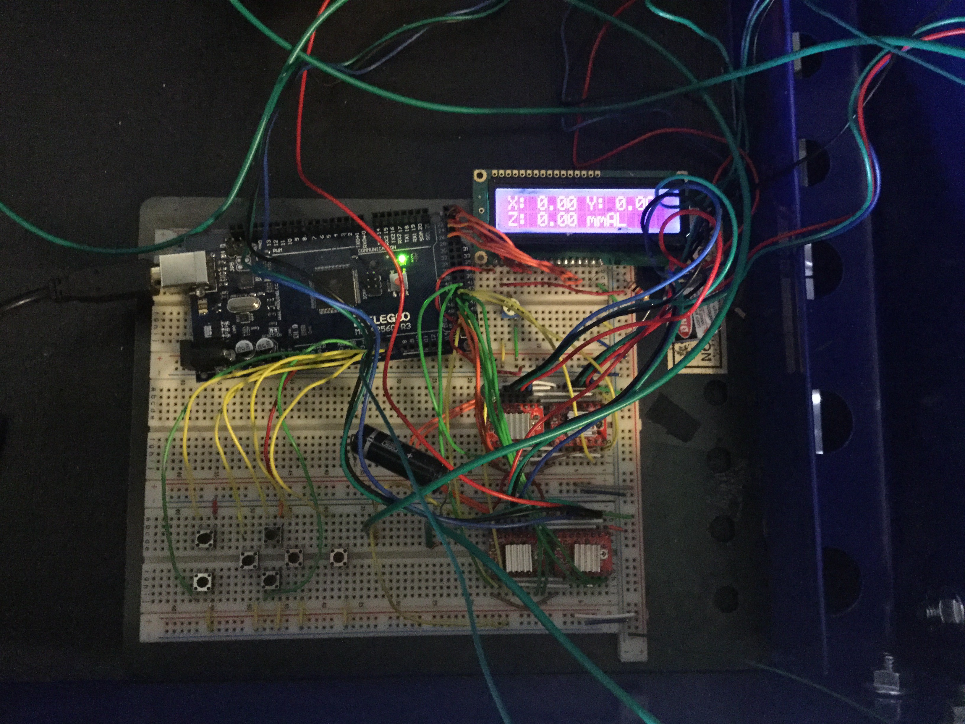
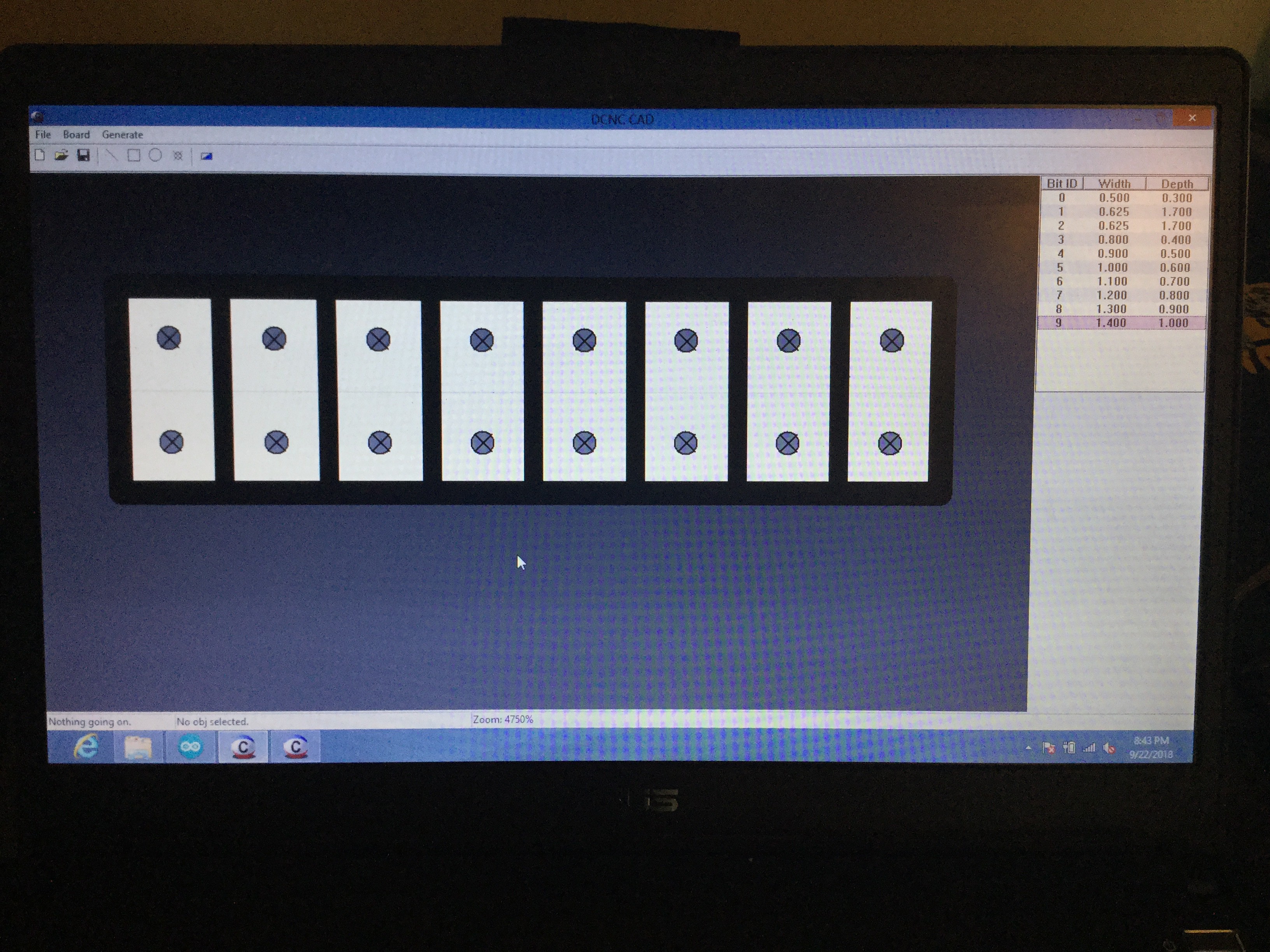
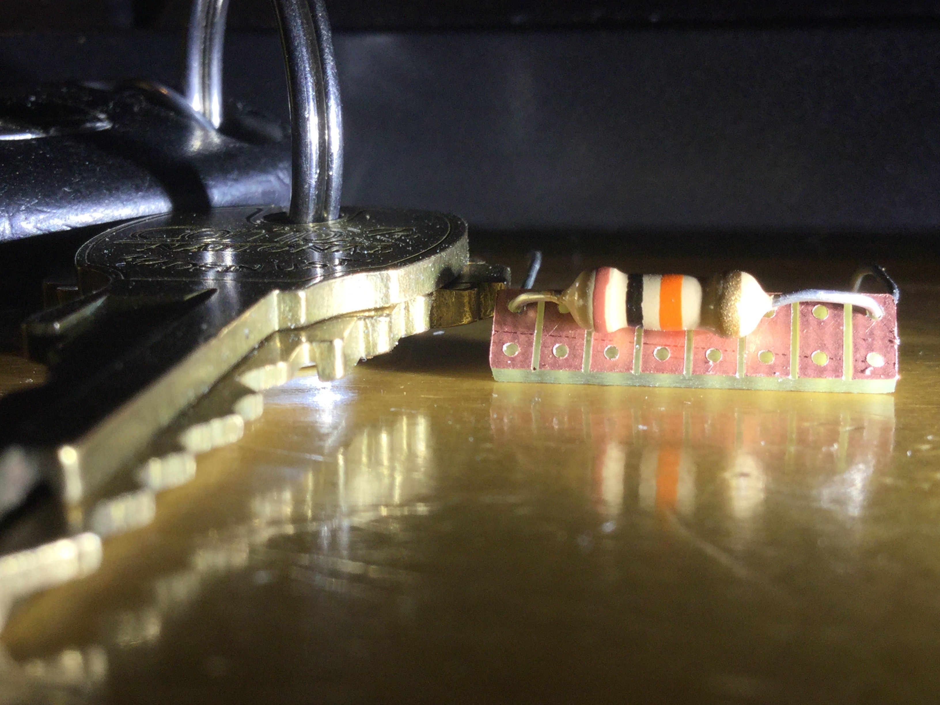
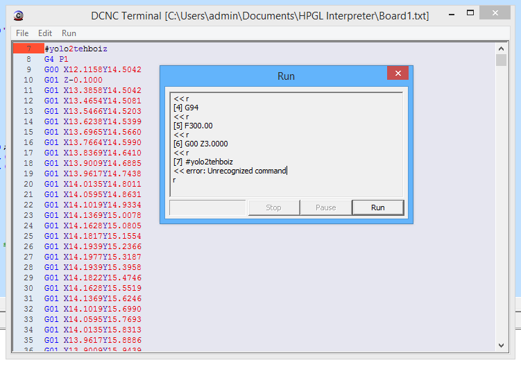
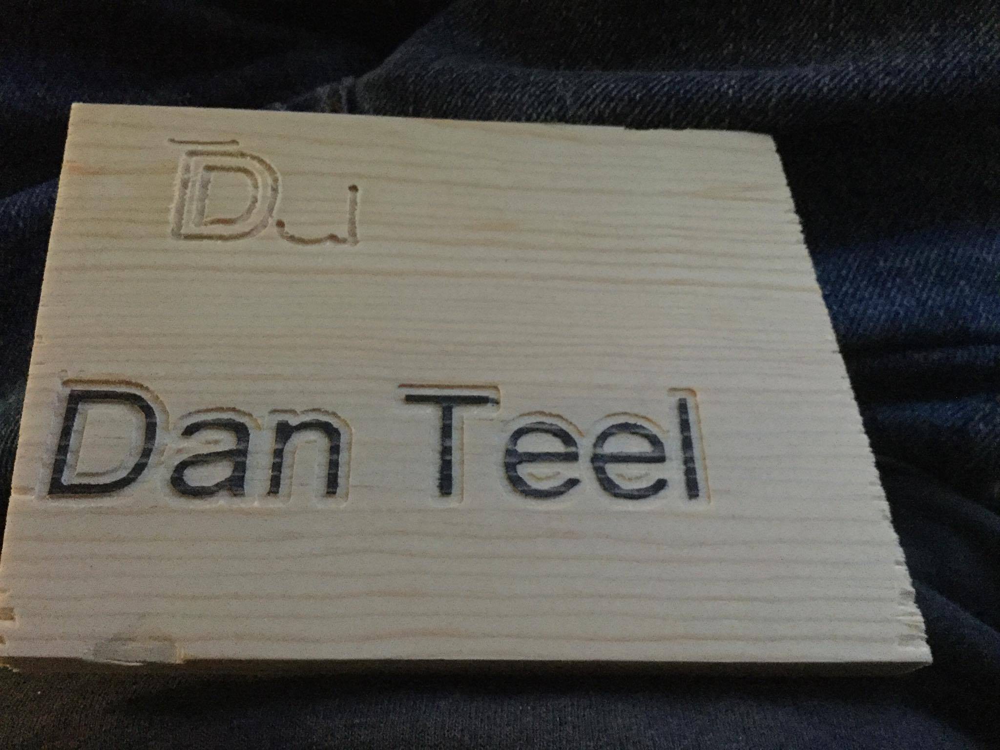
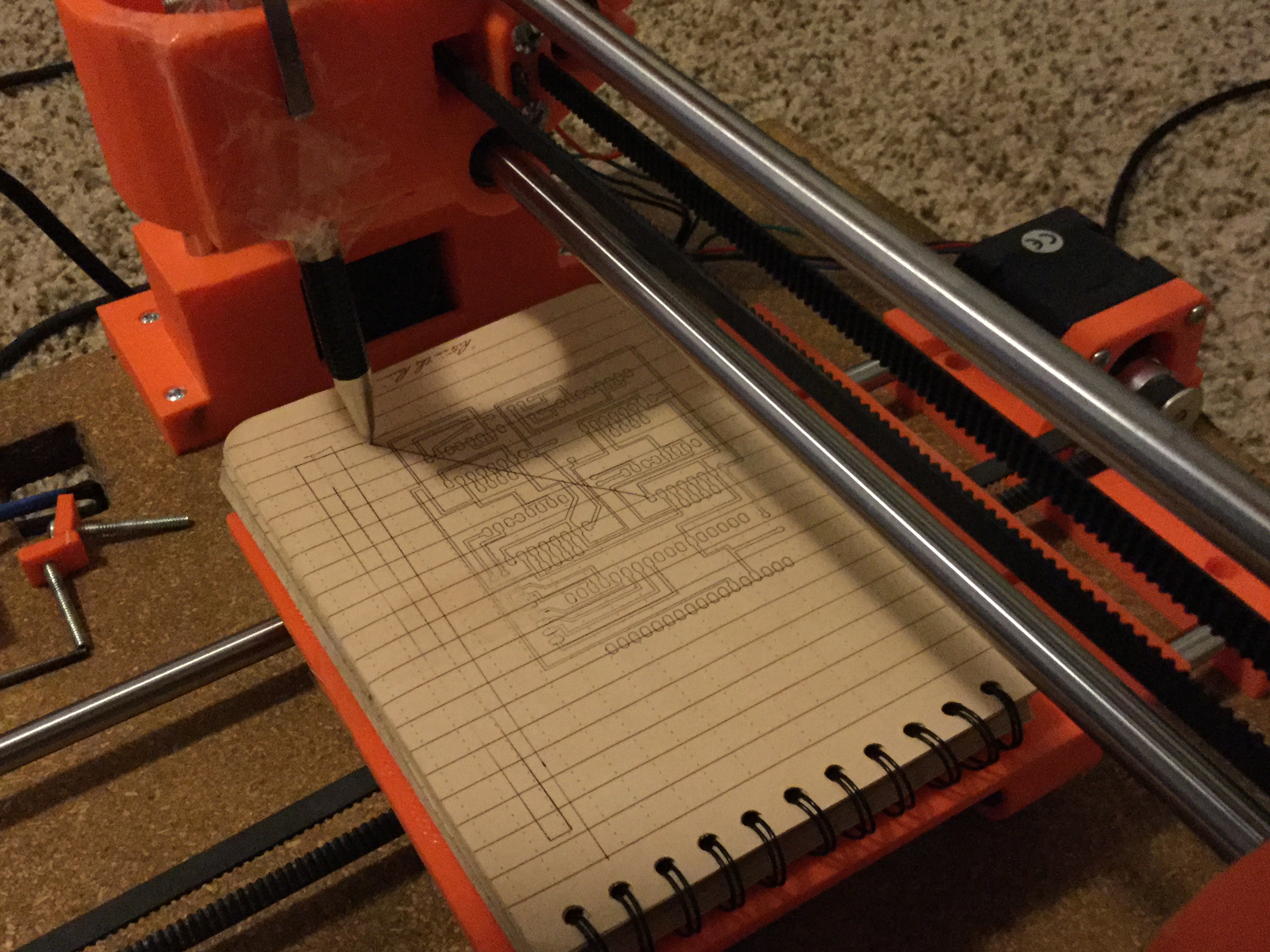
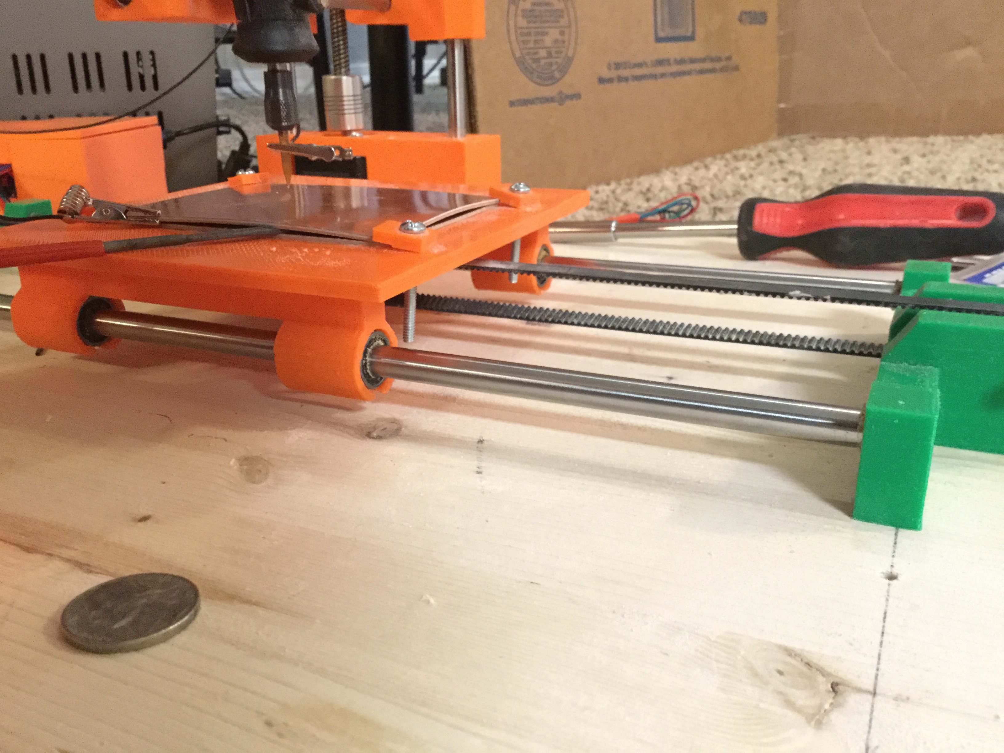
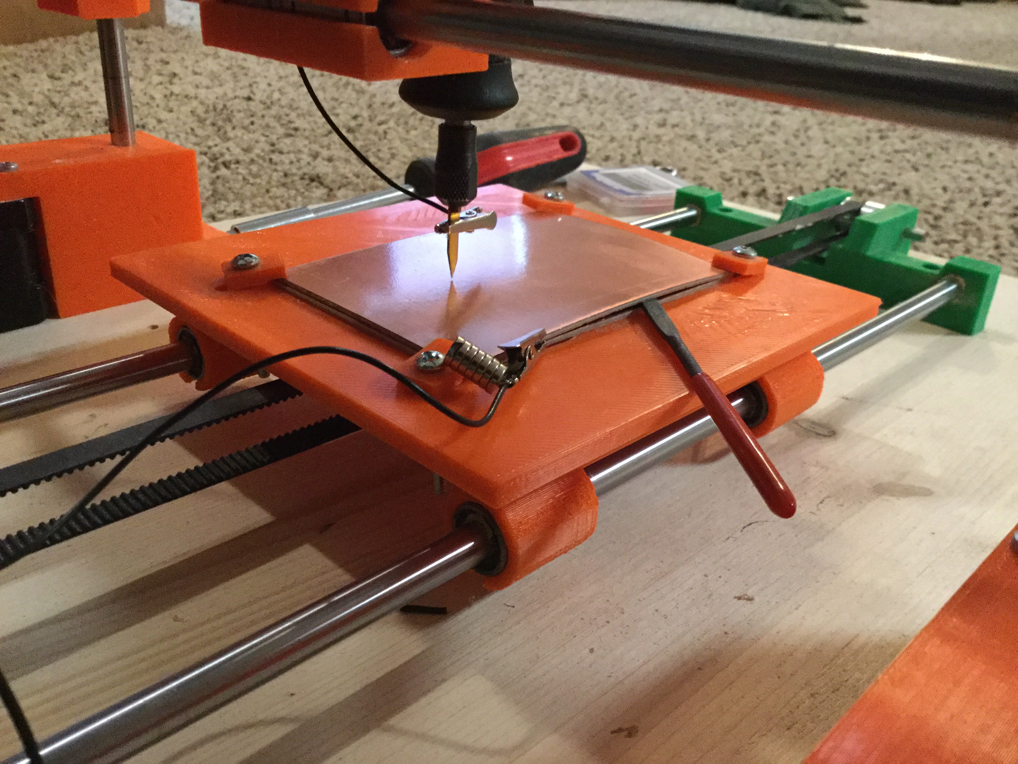
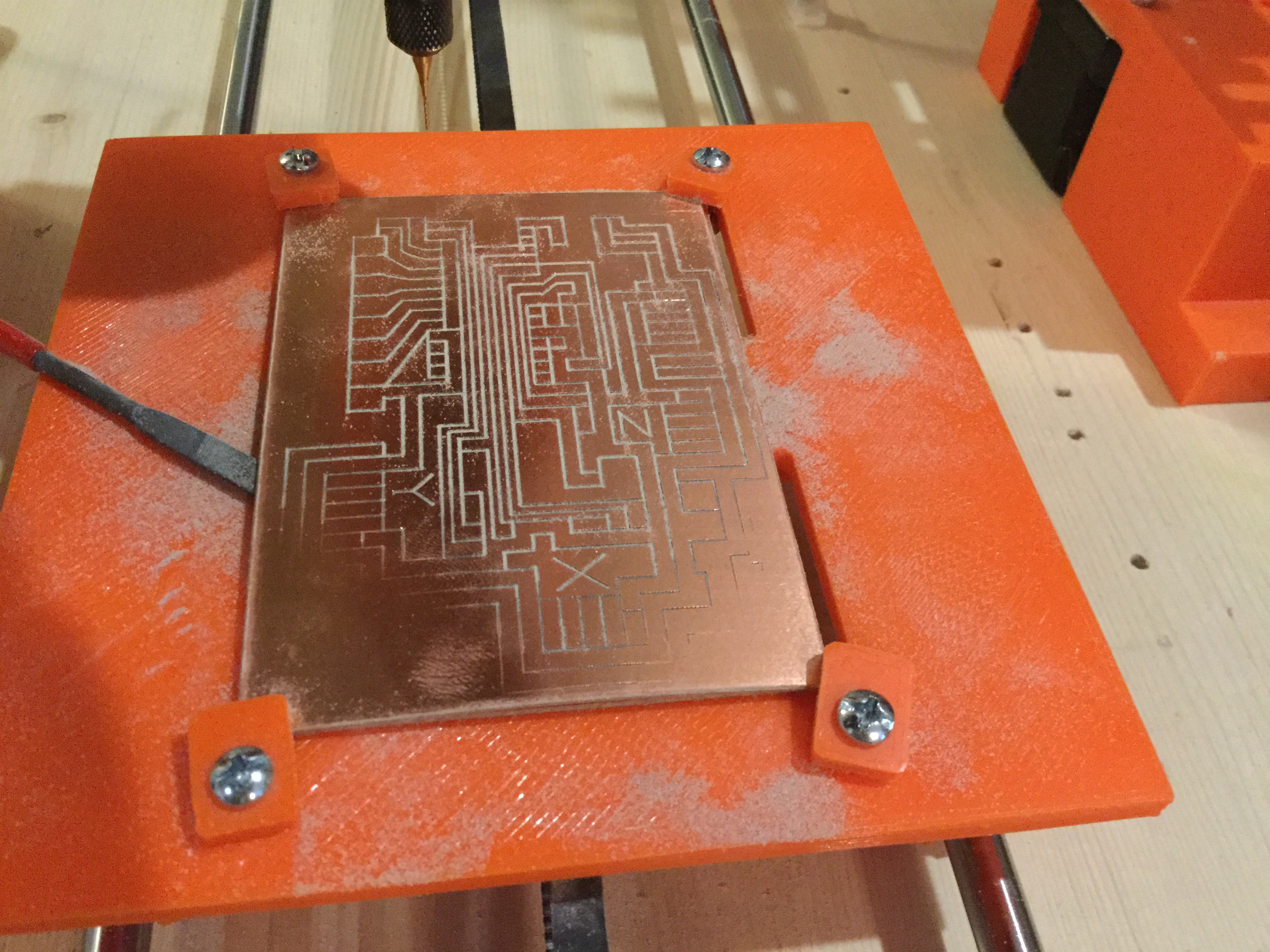
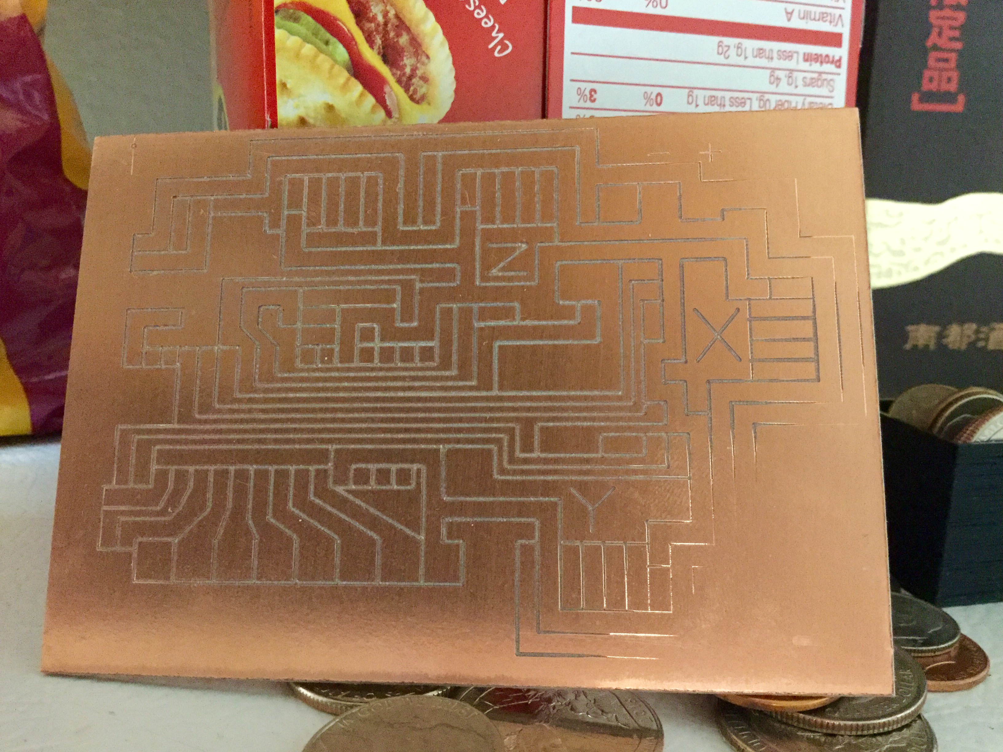
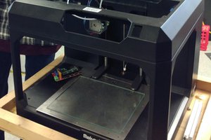
3D Printed PCB mill
3D Printed components and other hardware to make a PCB routing machine, which inherently can do other things.
Become a Hackaday.io member
Already have an account? Log in.
Just one more thing
To make the experience fit your profile, pick a username and tell us what interests you.
Pick an awesome username
hackaday.io/
Your profile's URL: hackaday.io/username. Max 25 alphanumeric characters.
Pick a few interests
Projects that share your interests
People that share your interests


 Thomas Bladykas
 fruchti
 AKA
AKA
This is my next build. Currently I'm building my second Prusa I3 clone. Fingers crossed ;)