A low-cost LFO that is particularily suitable to trigger envelope generators or to provide a clock signal for (drum) sequencers and pattern generators. The circuit is so simple that you probably already have most of the parts needed. The total cost of this build was about 1 euro.
The circuit is based on this 555 Timer Astable Mode circuit. I added a 100 Ohm resistor in series with the potmeter to avoid resistance dropping to zero because this would stop the 555 from oscillating. A LED was added as visual tempo indicator and because no project is complete without at least one blinkenlight!
 Nikolai Ovesen
 Dávid Máté
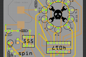
 kristina panos
 Matt Bradshaw