 dudeskidaddy
Quick aside: Prototyping with crappy jumper wires is bad. By accident we discovered our entire NRF-problem was caused by our combination of female-female and male-female jumpers. We're investing in a better supply of wires with all combinations of terminations.
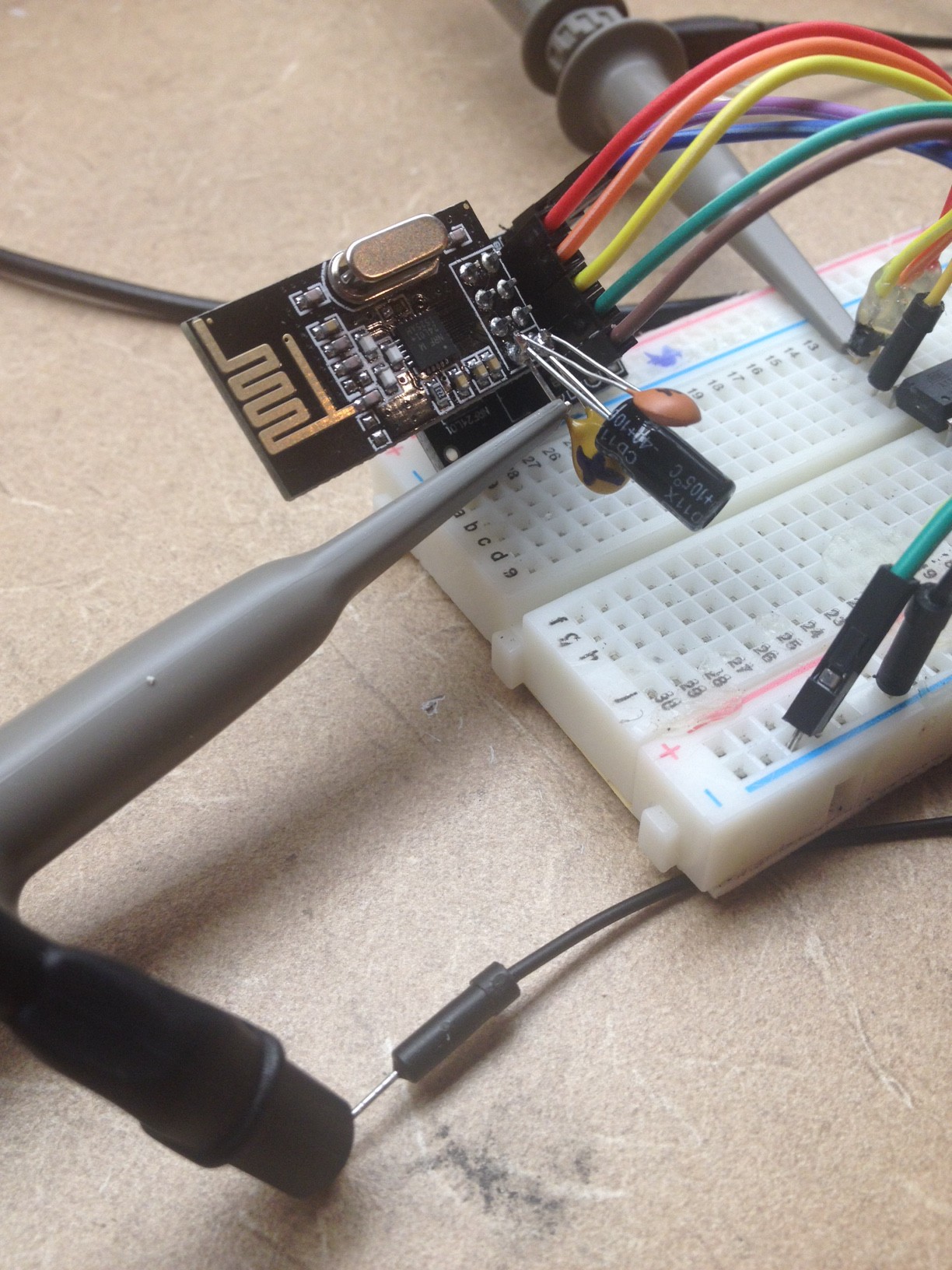
Probing the power and SCK lines
The NRF is thought to brown-out occasionally and/or the signal transitions are too slow to be detected unless you put a 10uF capacitor across the VCC/GND pins of the NRF. Don't want to go into too much detail here, but what we were hoping to see when we probed the power and signal lines is 1) Constant voltage on the power supply that never drops below 3v and 2) crisp, quick (i.e. vertical) transitions for the signals.
Results
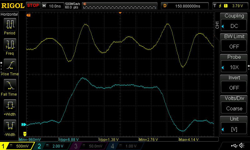
Above is a snapshot of the POWER (yellow) and SCK (blue) lines. At this time, there is a single 10uF tantalum cap across the NRF2401 power/gnd pins. As the SCK transitions from low to hi, the power drops significantly (to 2.76v) and the clock rise/fall slope is pretty bad. Pretty nasty looking: big droopy power and slow SCK transitions. We think the NRF is just barely operating...almost browning out and at the very margins of signal integrity.
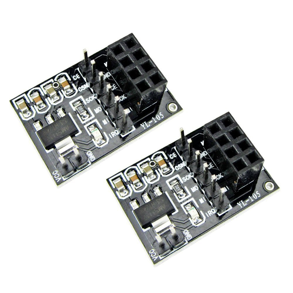
Next we tried these NRF2401 with an NRF breakout board (above) with no external capacitor. This PCB has its own on-board power supply (5v to 3.3v) and surface mount capacitors of unknown value. However in testing, the power supply and on-board caps seemed completely inadequate to supply steady current to the NRF and absolutely needed the extra 10uF capacitor to work.
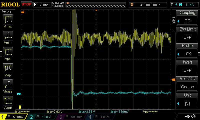
Next, we swapped out the 10uf Cap for a big 100uF. Above we see the large, slow power droops are much improved, but now we still see these little rapid, sharp power droops. This is probably because the 100uF cap is too slow to supply current for sudden bursts in load.
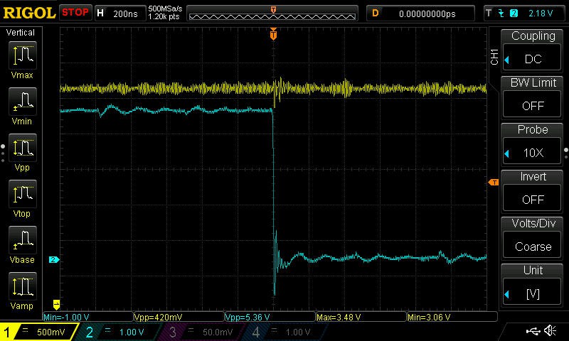
Finally we added 2 more smaller caps to handle these quick power loads: 100uF Tantalum, 10uF electrolytic, 0.1uf Ceramic. Pretty clear the NRF2401 needs a little babysitting on the power supply because finally the power signal and SCK lines look pretty good: very little power droop and sharp transitions on the signals. This was a fun exercise and let us play around with a lot of the features of our new Rigol toy. So again, the single 10uF still works but maybe the 3-cap setup might help somewhat when battery power is on the low side....another experiment?
Here is the NRF, NRF break out and the 3 capacitors.
Taking directly to the NRF
We found the following code to return the status of the NRF unit. It was nice to directly read the status in detail rather than simply not receiving a message on the receiver.
RF24 myRadio(7,8);

void setup() {
...
// provides a way for print to link to Serial.println
fdevopen( &my_putc, 0);
// public method in NRF library that prints lots of setting details.
// should not be all 0x00 for example..should have real data.
myRadio.printDetails();

}

// provides a way for print to link to Serial.println
int my_putc( char c, FILE *t) {

  Serial.write( c );

}
...and here is what we get from printDetails() on the broken NRF2041s. A bunch os 0xff.... The one good NRF we have returned the proper encoding for each setting. One thing to check easily is the Address Bytes since these are directly set by the NRF library's setAddress() API
STATUS = 0xff RX_DR=1 TX_DS=1 MAX_RT=1 RX_P_NO=7 TX_FULL=1
RX_ADDR_P0-1 = 0xffffffffff 0xffffffffff
RX_ADDR_P2-5 = 0xff 0xff 0xff 0xff
TX_ADDR = 0xffffffffff
RX_PW_P0-6 = 0xff 0x7f 0xff 0xff 0xff 0xff
EN_AA = 0xff
EN_RXADDR = 0xff
RF_CH = 0xff
RF_SETUP = 0xff
CONFIG = 0xff
DYNPD/FEATURE = 0x7f 0xff
Data Rate = 1MBPS
Model = nRF24L01
CRC Length = 16 bits
PA Power = PA_MAX
Discussions
Become a Hackaday.io Member
Create an account to leave a comment. Already have an account? Log In.