GKOS Keypad
With the 6 GKOS keys, directly connected to Arduino I/O pins, it is possible to type any text and enter most functions found on the PC keyboard (Alt, Ctrl, Tab...).
GKOS Hardware
The GKOS hardware is very simple, requiring only six pushbuttons to be connected to Arduino pins and to ground. In the Arduino Pi project, the analog pins are used taking up all the analog pins (if Arduino Uno is used).
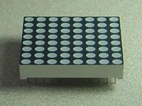
LED Matrix
The LED matrix is controlled using row-column scanning.
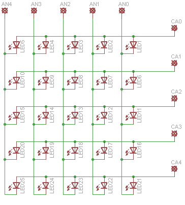
LED matrices are often arranged in rows of common anodes and columns of common cathodes, or the reverse. Here's a typical example of an 8x8 matrix, and its schematic:
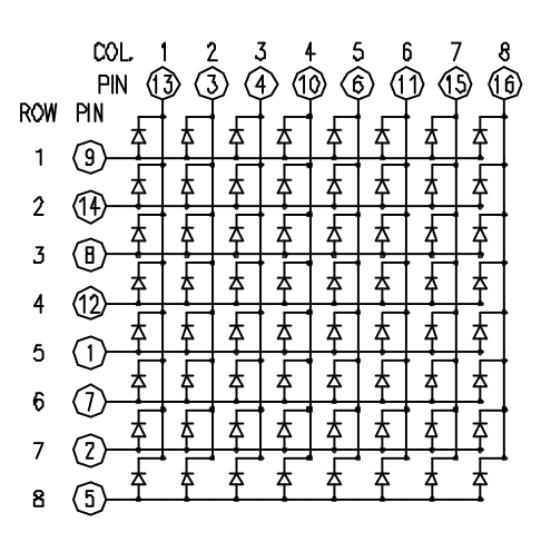
These can be very useful displays. To control a matrix, you connect both its rows and columns to your micro-controller. The columns are connected to the LEDs cathodes (see Figure 1), so a column needs to be high for any of the LEDs in that column to turn on. The rows are connected to the LEDs anodes, so the row needs to be low for an individual LED to turn on.
To control an individual LED, you set its column high and its row low. To control multiple LEDs in a row, you set the rows high, then take the column high, then set the lows row or high as appropriate; a low row will turn the corresponding LED on, and a high row will turn it off.
Similar schematic is used for a 5x5 LED matrix. I used the code from the below link :
http://www.instructables.com/id/5X5-dot-matrix-on-Arduino-gets-text-from-pc-2/
This link also includes the pixel maps for the 5x5 LED matrix.
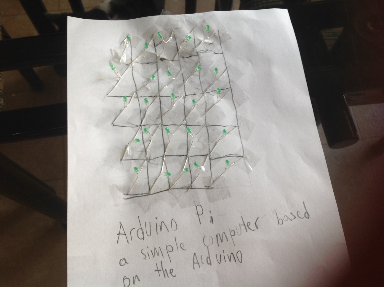
For the LED Matrix, I will construct the circuits on a piece of paper in which the graphite is the wire as graphite is conductive.
Bitlash
Bitlash is an open source interpreted language shell and embedded programming environment for Arduino. The Bitlash shell runs entirely on the Arduino and supports many of the familiar Arduino functions. Bitlash interprets commands you type on the serial port or send from your favorite PC-side programming environment. I have integrated Bitlash with the GKOS keypad so instead of using a serial port to enter commands, the GKOS keypad is used instead.

Bitlash website:
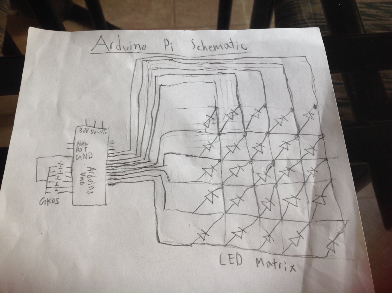
Hardware schematics and pictures
Schematic:
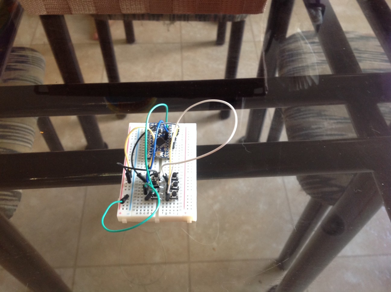
Breadboard:
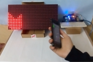
LED Matrix:
More Information
For more information, visit the official website at:
http://iscienceluvr.github.io/arduinopi
Stages and Goals
Stages of development and production (will be updated with when each stage was finished):
- Stage 1 - Design (finished on June 3, 2014)
- Stage 2 - Code Verification (finished on June 10, 2014)
- Stage 3 - Part Ordering (finished on June 23, 2014)
- Stage 4 - Hardware Verification
- Stage 5 - PCB Testing and Production
Goals:
- To create a cheaper DIY computer
- To combine the best of Arduino and Raspberry Pi
- To create a simpler electronics development board

 mostafa2100.abcreno
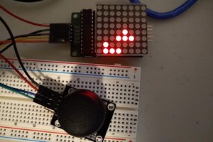
 Jason
Jason
 Sagar 001
 AdroitConfusion
very good one to share, its very nice.
this connection are very organized,and that is good.
http://bramjak.com/2016/07/فتح-المواقع-المحجوبة/