 esieapstvelo
Operation is simple, the user connects the phone to the GPS with Bluetooth. It connects to the GPS map. He writes his destination on the GPS OsmAnd application. Then the GPS shows him his way through the LEDs.
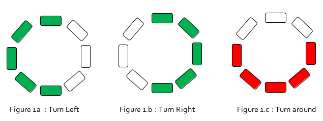
Here below are the GPS indications:
In this project, we will use a GPS application available on Android or IPhone, OsmAnd, a mapping application and navigation with access to free data OpenStreetMap. This application is available offline, that is to say that one can use this application without using the cellular data (3G or 4G).
We use an Arduino micro type microcontroller as it is quite simple to use and is inexpensive. It is connected with a Bluetooth headset.
This headset is the link between the Arduino board and telephone. To indicate the direction to the user, we use a ring of 24 LEDs connected to the Arduino board. These are Neopixel LEDs, they are the most efficient LEDs. We can control the color and light intensity of the LEDs.
To transmit information from the GPS map application OsmAnd and Arduino we used the audio signal. In fact, the GPS information data are send with an audio signal. This requires that the Arduino board recognizes the signal and transmit the information to LEDs to indicate the direction to the rider. There are several possible ways to analyze the audio signals. We can use the signal frequency to transmit information. For example, to turn left it is enough to send a signal with a frequency of 440 Hz and a frequency of 800Hz to turn right. We can also use the intensity of the signal or the amplitude. But we have chosen to use the signal frequency. This is the most reliable and most effective way we've found. From there we set frequencies for each direction of GPS. We modified the pack of voice present in the OsmAnd application. We replaced these sounds with our frequencies. With the Audacity software, we have created continuous frequency sounds. For example, instead of saying "turn right" the GPS will send a sound frequency 50Hz. The signal will be analyzed by the Arduino board and turn on the LEDs on the right (see Figure 2.b).
The signal sent by the phone arrives in the Bluetooth headset, the output of this headset, the sound signal is amplified. Without amplification, the Arduino board receive a signal between -0.8V and 0.8V. This signal is too weak to be analyzed. So we built an amplifier circuit which allows the Arduino board to receive a signal between 2V and 4.5V (see figure 3). Before to amplifying the signal we were unable to determine the frequency of this signal. We spent a lot of time trying to understand why, and we found this solution on a website. Arduino inputs are designed for positive voltages between 0 and 5 V. The function of the circuit that I present today is, first, to amplify the signal so that it is easier measuring by means of the Arduino and, secondly, to superimpose a DC voltage of 2.5 V so that the voltage received by the Arduino is never negative.
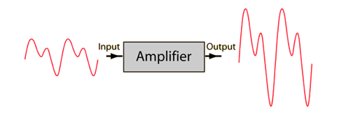
Figure 2. An example of amplified signal.
To determine the frequency of the received signal, we use the library function PULSEIN in Arduino. This function measures the period of the sound signal (see figure 4).
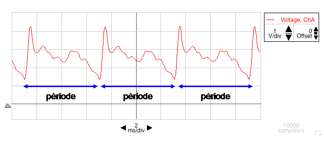
Figure 3. An example of period
The Frequency is the duty cycle multiplying by the inverse of the period. The duty cycle corresponds to 61 000 in our case. It is measured with an oscilloscope.
So we get the frequency of the audio signal. Now we can send the information to LEDs.


 Nick Johnson
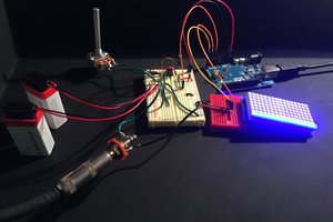
 Will Markley
 mircemk
hi
Can I use an esp8266 or nrf24l01 module instead of Bluetooth headset?
What modifications to code required?
Thanks