 andyknitt
So what is this thing?
At the most basic level, it's just some remotely-controlled water valves. How they're controlled and used is where things get fun.
There are two main methods used to control these water valves: A simulated, wireless-enabled nozzle attached to a hoseline, or any type of WiFi device that has web-browsing capability. These two conrol methods are used in two different training scenarios:
Simulated Fire Exercises
When conducting simulated fire exercises in a building where you can't flow water, here's how you'd use the system:
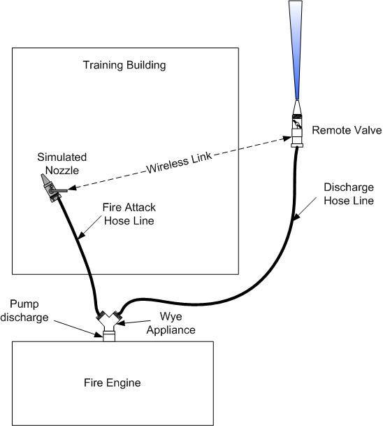 A wye appliance is connected to the discharge of the fire pump. A wye simply splits one line into two. The interior attack hoseline is connected to one side of the wye, and the other side is connected to the training system valve outside the building. The simulated nozzle with the wireless transmitter is attached to the end of the interior attack line.
When the fire pump discharge is opened, both hoselines connected to the wye are charged. This allows the interior attack crew to operate with a fully charged hoseline. When the interior attack crew opens the "bail" on their simulated nozzle, a wireless signal tells the remote valve outside the building to open, and water flows. The pump operator must then respond accordingly by adjusting the throttle, monitoring tank water levels, wetc.
Dedicated Pump Training
To use this system during dedicated pump operator training, here's how you could set it up:
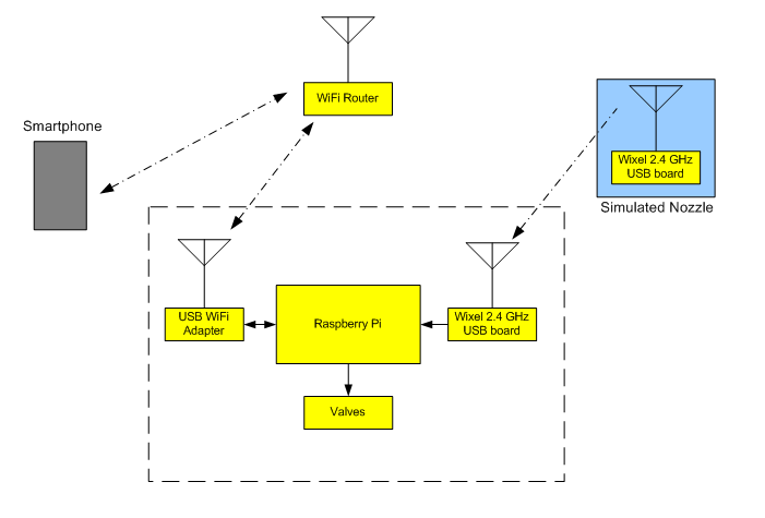
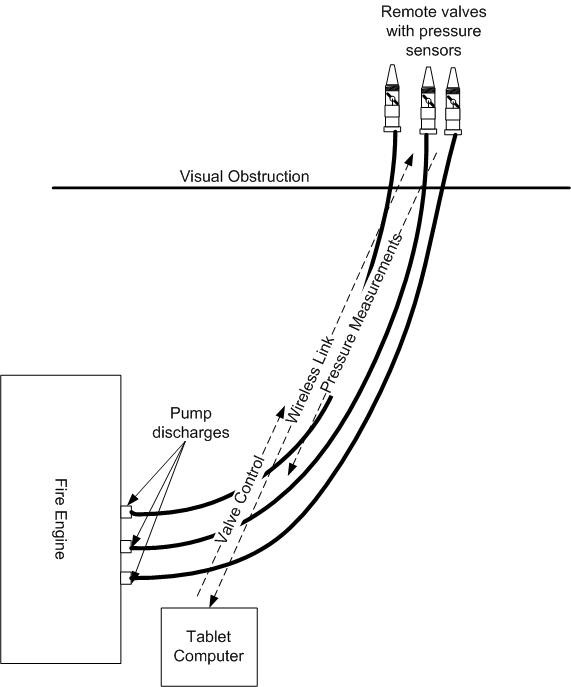 In this scenario there is no interior attack crew, since we're just training a pump operator. The remotely controlled valves are placed out of sight of the student/fire truck and are connected to various pump discharges on the truck. The instructor can remotely control the valves via smartphone or tablet with a web-browser interface. Predefined valve opening and closing sequences can be preprogrammed and run automatically to simulate actual fire water flow scenarios, and the instructor is then free to coach the student without having to worry about keeping track of which lines are flowing. Real time pressure and flow feedback is provided to the instructor's smart device via the web interface, and all data is logged for post-drill evaluation.
Design Aspects
There are a lot of different aspects of engineering that go into this project:
- Water pressure, flow, and friction loss calculations and measurements
- Electromechanical interface (H-bridge valve control)
- Wireless connectivity (range analysis, system design, etc.)
- Analog sensing interface (pressure sensors)
- Mechanical design
- Electromechanical interface (simulated nozzle)
- Power supply and budgeting
- Aesthetic design (HA! Right! It's ugly, it's all about function for now, form will follow, maybe?)
Here's a video to explain how it works until I get the writeup completed.

This work is licensed under a Creative Commons Attribution-NonCommercial-ShareAlike 4.0 International License.
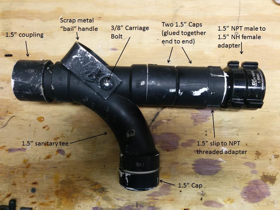


 The Wixel is simply mounted to the inside of the nozzle body using double sided tape in the vicinity of the magnet on the carriage bolt. When the bail is actuated, the magnet rotates with the bolt inside the nozzle body. By fine tuning the location of the magnet and the Wixel, it's easy to get the reed switch to activate when the nozzle is "open" and deactivate when it is "closed". Power is supplied to the Wixel by two AAA batteries in a holder that's mounted in the "pistol grip" of the nozzle (the PVC sanitary tee). A slide switch has been superglued to the AAA battery holder to allow power to be turned on and off without having to remove the batteries. This battery holder and switch are covered by a PVC cap when in use so that the switch can't be accidentally deactivated as the nozzle gets drug, banged, and beaten around by ambitious firefighters.
 This can look a little confusing if you've never seen an H-bridge before, so let's step through it. The two terminals of the solenoid are connected to the S1A and S1B points. If we apply 3.3V to point H1B, that will turn on NPN transistor Q2 and allow current to flow from point S1A to ground. At the same time, that 3.3V also turns on NPN transistor Q3, which pulls point H1C low, which in turn turns on PNP transistor Q4. When Q4 is on it allows current to flow from the 9V supply to point S1B. So now we have current flowing from the 9V supply, through Q4 to the solenoid coil connected at S1B, through the solenoid coil to point S1A, and from S1A through Q2 to ground. The current path is complete, and the solenoid will activate, turning the water valve on. Since this is a latching solenoid, we only need to apply 3.3V to point H1B for about 500ms. This gives the solenoid enough time to fully activate and latch, and then we can remove power.


 Kenji Larsen
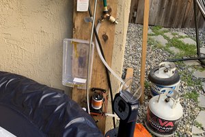
 alexwhittemore
 infinityis
 mark.reeves.78
As someone who just got to witness a test burn for a fire detection/sprinkler system, I must say - this is a wonderful idea. My industry can only do so much before the firefighters have to come in and finish the job, and they are only as good as their training. This should prove must useful. Something that could be added to this for the benefit of the hose crew's training - maybe a laser tag like system to allow for "time to/time on" target tracking. The space is available.