 Enrico
I am playing with LEDs for few month and during that time some little projects were born, but now I need a system to handle the logical part and the power distribution. I simply just can't use an Arduino board, or any other development board: I need a proper power handling embedded in a small space, all in one PCB, with some particularly high power requirements. And being Arduino compatible. This is Lino.
It will be used to power up the Glighter-S modules in a compact fashion, finally reaching something similar to a complete lighting working system.
Project purpose and board review
This board is designed to power up any power LED, motor and/or anything which requires up to 10W and can be controlled in PWM. Lino supports in hardware the control through physical, glitch filtered, inputs like buttons and encoders.
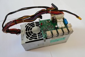
In the picture below is shown the board with its main interfaces:
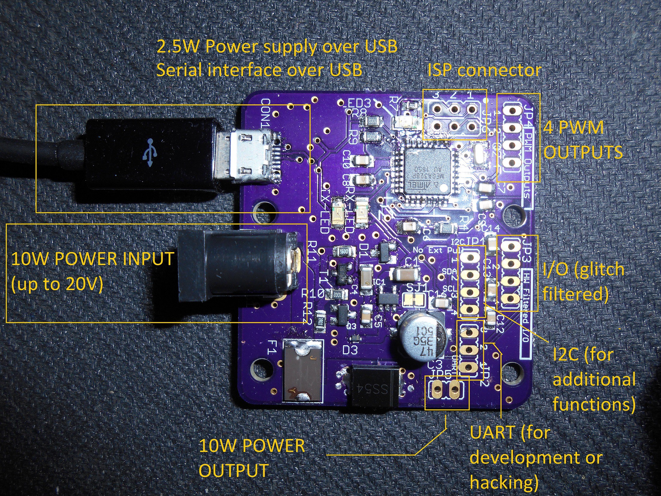
More protocols are supported onboard, like I2C and UART (real or through USB emulation). With the proper firmware running on Lino, terminal commands are supported using the serial protocol, connected with the Atmega (the main MCU) mainly in two ways: with USB through an emulated terminal, or directly with the microcontroller's UART, supporting then any communication with a serial device, like the ESP8266 and with no additional circuitry, since everything is working at 3.3V.
Since this board can communicate using UART or I2C, this setup is scalable, making it capable to drive more Lino boards connected with each other.
Board characteristics: the union of Atmel and Microchip in practice
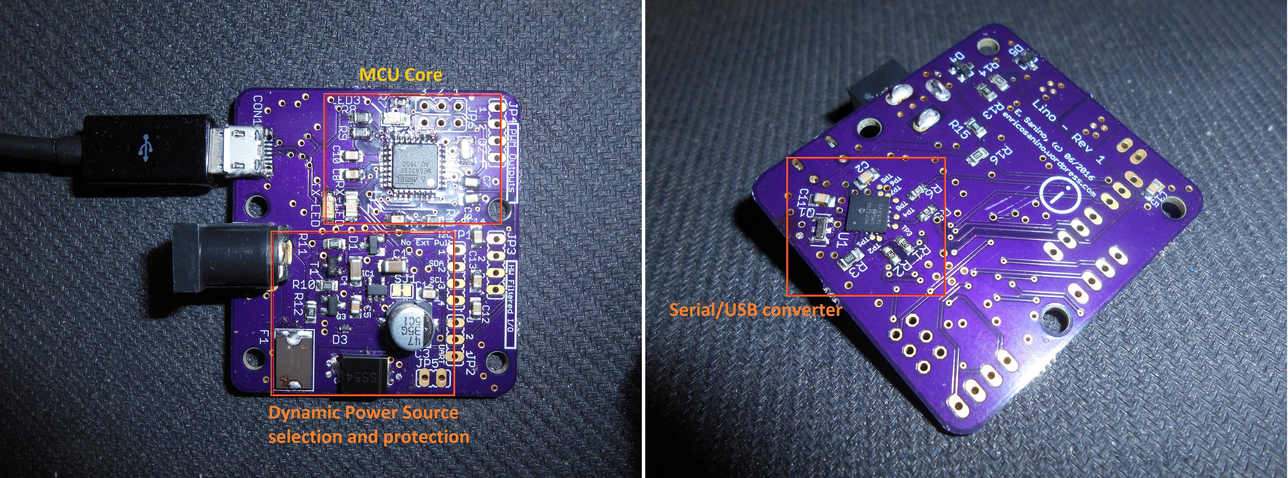
Here is shown the main blocks of the board. It is a kind of celebration of the acquisition of Atmel from Microchip. It is used an Atmega328P microcontroller and the Microchip MCP2200 USB to Serial converter instead of the FTDI, which instead would costs truly a lot.
Below, the block diagram of the project and a picture which shows where physically things were arranged on the board:
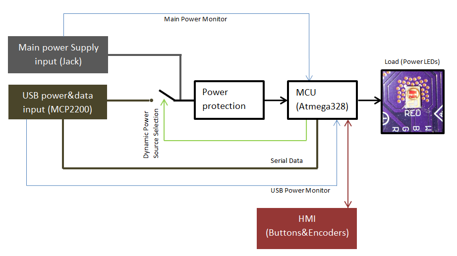
Everything is almost self-explaining. Briefly, the HMI (Human-Machine Interface) can support a single Encoder with an integrated button to minimize the commands and user interface complexity, but with firmware mods can be anything else. The load used to test the Lino board are 4 Glighter-S power LED drivers, which are lighting up a LED satellite, all these test boards are designed in Glighter-S project page.
The controller core is the Atmega328P, which is used to keep the hardware Arduino compatibility. With the low cost and well supported Microchip MCP2200 I can obtain a neat working system interfaced with any PC or serial device: in fact I have also a pure serial connector, with 3.3V voltage swings. For example it can talk with the famous ESP8266 with no additional circuitry.
A bit of more explanation is instead necessary for clarify the power handling.
Dynamic power source selection
The selection is performed by the MCU (green dashed line in pictuire below), while a default safe state is kept when the MCU is not driving the switch. All the voltages are monitored, in order to allow the firmware to make the right selection. The priority of the source selection is given to the external power source.
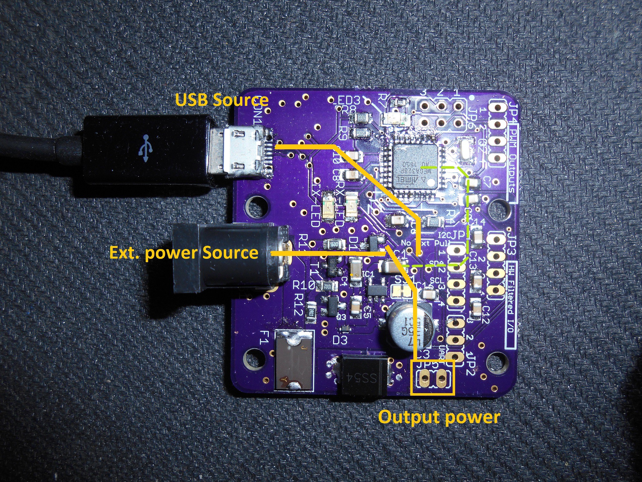
The USB power is limited, since this board can be used directly connected to a PC, able to provide, normally, no more than 2.5W per USB port. Therefore, to use the entire power capability, an external power supply shall be used.
Due to the extremely high input voltage range, the power source selection is achieved in the firmware while the hardware is fully protected against misbehaviours and short circuits. After all, it is a personal project and burning a board is tedious and I can't afford this, prevention is better. As also in professional environments, anyway.
Below just a brief of the supply characteristics:
| Electrical characteristics | Min | Max |
| Input voltage | 3V | 20V |
| Maximum supported power (USB only) | 2.5W | |
| Maximum supported power (Power Jack) | 10W | |
| Maximum supported power (Power Jack + USB) | 10W... |


 Martin
 piat.jonathan
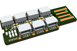
 rbtsco
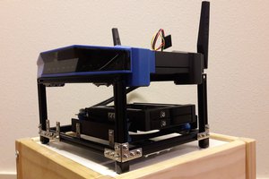
 Stanislas Bertrand