 Adam M
I've decided to keep a log here of the costs to fix the printer so far. I don't count filiment because it's an expected cost.
| Description | Qty | Price |
| Printer | 1 | $200.00 |
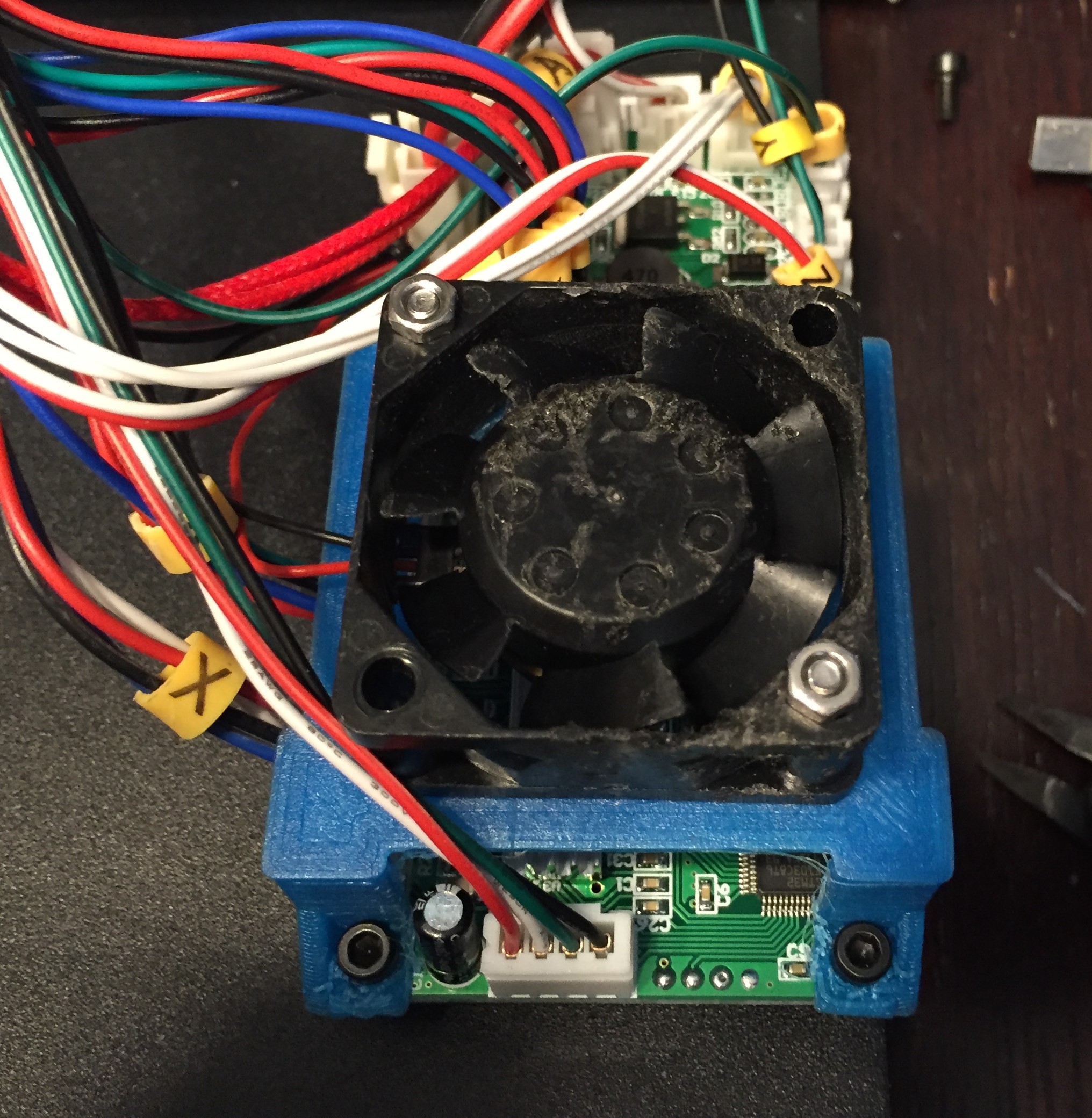
| Cooling Fan 40mm | 1 | $7.20 |
| M3 Screw Kit | 1 | 15.69 |
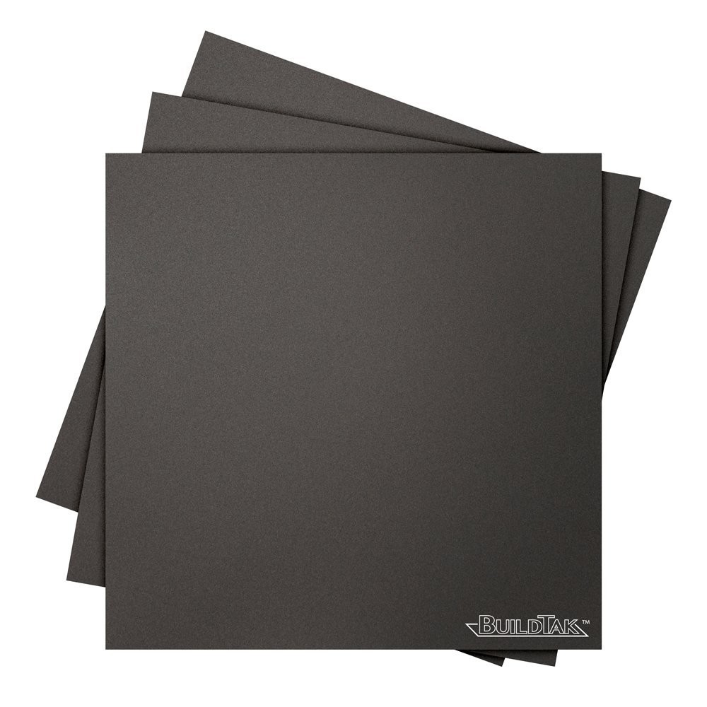
| BuildTak 4.5in x 4.5in | 1 | 8.20 |
| Total | $231.09 USD |


 Michael
 Zoé
Zoé
 Andrew McAteer
Nice one, it will be much helpful for the small business needs. https://fantaserye.su/