Close
0%
0%

OpenSourcePowerSupply

An automated lab power supply power with no mains power interface.

Similar projects worth following

Every Electronics Engineer needs a source to pull the Electrons around their creations and projects. The goal of this project is to develop an Open Source Power Supply which can be built by anyone with a soldering iron, without mains power in the design compromising safety. The OSPS will fulfil these main requirements:

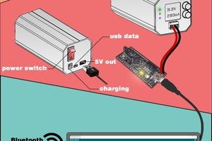
  • Low Voltage DC Power Supplies, such as a laptop power supply, will be used as the main input for the PSU. This removes any need to protect against mains in the design making it safer and reducing the cost. The unit will also be able to utilise USB as an input supply for lower power needs.
  • The design will have control of voltage and current supplied.
  • The device will be able to be controlled by a front panel User Interface with a screen and switches, or by a software interface.
  • Logging will be able to be done on the device and egressed to the Desktop application.
  • The target cost to someone replicating the design is £100.
  • All aspects of the design will be done using Freely Available Software, cross platform and Open Source where possible.

Future enhancements include:

  • Integrating USB Type C with an aim of understanding the USB Power Delivery

  • Power Supply Deisgn

    Henry Lovett07/08/2016 at 21:44 0 comments

    The main aspect of the design revolves around the power supply. An ideal power supply can supply a perfectly stable voltage under any output load condition and any input power with 100% efficiency. However, supplies that get close to this ideology are out of the budget of most hobbyist engineers. The assumption here is most engineers have at least one old laptop / device power supply lying around, or at least spare USB port, to provide the input to the device. By removing the mains voltages from the design, the construction can be simplified and no worry of safety is involved, as well as reducing the cost.

    Every circuit has at least one power supply on the board. These are usually a Linear Regulator or a Buck (Step Down) Switched Mode Power Supply (SMPS).

    A Linear Regulator is the most simple power supply. By dropping a voltage over a MOSFET, the output voltage can be regulated and maintained with very little fluctuation in output voltage (ripple). This simplicity is at a cost of power dissipation. The efficiency of the linear regulator is a function of the voltage drop and current draw through the device, and this limit is ingrained in the design of the device. The larger of a power dissipation needed, the larger the device, and requirement to extract heat from the system, and also less efficiency.

    The SMPS comes in as a higher efficiency device (reaching >90% efficiency in some cases). This results in less power dissipation of the device, so less heat. However, complexity arises in the design and implementation, requiring a controller, MOSFETs and an Inductor. SMPS outputs have ripple voltages and higher switching frequency components. A well designed SMPS can have very little (<10mV) ripple, but is still unsuitable for sensitive circuitry, such as RF.

    In the OSPS design, a Linear Regulator will be unsuitable on it's own due to potential power dissipation in worst case (2A @ 15V drop = 30W of heat to dissipate, for example) and would limit the operation of the device. A SMPS can be made variable, but at the expense of ripple voltage and response (assuming stability is gained at the expense of response), and would also be unsuitable on its own as a generic power supply for these reasons.

    The OSPS will use both an SMPS and a Linear Regulator. By combining the two types, the power dissipation in the linear regulator can be reduced by dropping the majority of the voltage by using the SMPS. The output voltage will then gain the advantages of the Linear Regulator without complex heat dissipation.

    The added bonus of this design is a current monitor can be placed between the SMPS and Linear Regulator, meaning the losses seen over the current measuring aspect can be hidden by the Linear Regulator.

    The final aspect of the power supply design would see the inclusion of a Boost SMPS. This can be utilised in the case where a larger output voltage than the input is required. The compromise made with a Boost supply is in the noise, efficiency and stability of the circuit. A combined Buck/Boost supply will add the functionality with minimal extra components.

    The controller of the design will be able to control the output voltage in both the Linear Regulator and SMPS. By knowing the input supply, output supply, characteristics of the internal SMPS and Linear Regulator, the controller will be able to calculate the internal voltages needed to provide the required output, and also give the limitations of the device if too much current is attempted to be drawn.

  • Low cost, low volume

    Ashley Robinson07/07/2016 at 19:57 0 comments

    A challenge during this project will be to specify components which are low cost when purchased in low volume. Mechanical components can be inexpensive with an obvious trade off in quality. Electronic components used in this design will be in expensive individually but quickly combine to create an expensive BoM. Low cost fabrication is available but delivery times are horrendous.

    Designing in a microcontroller is the first of these hurdles but with a slightly different twist. The user needs to transfer a binary image from their computer to the microcontroller. It cannot be assumed the user has a selection of programmers standing by so the BoM also needs to include this item. Low cost programmers from vendors come in at around £20 so this out of the question.

    The Arduino UNO (Atmel ATmega) is an inexpensive dev board but lack some key functionality desired for this design. The microcontroller is held in a socket so can be programmed and transferred to the design which is nice. The same goes for the TI Launchpad except at a lot lower cost. Open source DIY programmers are available and may come in at a cheaper price but would be a project in its own right.

    Hacking a dev board is the way to go. Throughout the range available the ST Nucleo boards come in at a lower price than the competition (the NUCLEO-F302R8 is only £6.48 from Farnell ) and packs a plethora of peripherals. The tricky step to decrease the BoM cost even further is to de-solder a LQFP package from the board and solder it down on power supply PCB. The remaining part of the dev board can be hacked to open the programming interface, add some headers and program the microcontroller in-situ. The user also has a programmer handy to upgrade the design as required.

  • Mechanical concept generation

    Ashley Robinson07/03/2016 at 21:30 0 comments

    Since the last log entry we have been considering different concepts for the enclosure. The caseworks for OSPS will have mounting bosses for the PCB and cut out sections for connectors. The more important aspect of the design is the user interface. The design decisions at this stage will be reflected in the usability of the device and the overall cost. Seven segment display or LCD? Tactile switches or rotary dials?

    Our approach differs from supplies typically found in the lab because the large AD/DC power supply section won't be contained in the design. This means the design can be smaller and more portable hopefully taking up less space on the desks of software engineers. Good power supplies usually have simply interfaces with as few a components as possible which will be a good goal to take forward in the design. Creating a simple GUI for the PC application that mirrors the mechanical interface will also be challenging but should make the design stand out.

  • Specifications

    Ashley Robinson06/29/2016 at 20:19 0 comments

    Our bench top power supply project has been submitted to citizen scientist as a piece of lab equipment. We started knowing roughly what we want to create but the first steps of the project has been about clearly specifying the final outputs.

    The user requirements are complex as a user will not only interact with the final design but also construct, maintain and upgrade. We have assumed a basic skill level restricting the technology available. Access to a reasonable set of tools is also assumed and fabrication houses recommended must be low budget and low volume friendly.

    The technical requirements are an exercise in defining goals within the limit of our reach given timescales and resources. Reinventing the wheel would likely score many points but is useless when the hackaday prize deadlines pass us by yet hacking together another unrepeatable mess of hot glue and stripboard will be just as useless.

    In parallel we have been landscaping existing commercial/open source designs and researching nice tricks we can play to reduce final BoM cost and improve performance. Next up will be sketching designs and the beginnings of formal CAD.

View all 4 project logs

Enjoy this project?

Share

Discussions

Similar Projects

Does this project spark your interest?

Become a member to follow this project and never miss any updates