 engunneer
(October 2015)
With new PCBs in hand, I assembled two to get going on testing. I still need to get the IR working, and the value of the phototransistor pullups still needs to be determined. I also ordered stencils for this version of the PCB from OSHstencils, and used a mini hotplate to assemble the backside of the boards. The front side was stenciled, but I did the reflow by hand with an iron.
Too bad the silkscreen was wrong by 180 degrees on the Layout. Or at least I thought it was. In the end it wasn't. Unfortunately, I had assembled two boards before discovering this. I remembered a good hack from hackaday about using heavy gauge solid core wire to upgrade a soldering iron to a desoldering iron that could be used to heat two joints at once. I adapted this for the 4 joints on the WS2812.
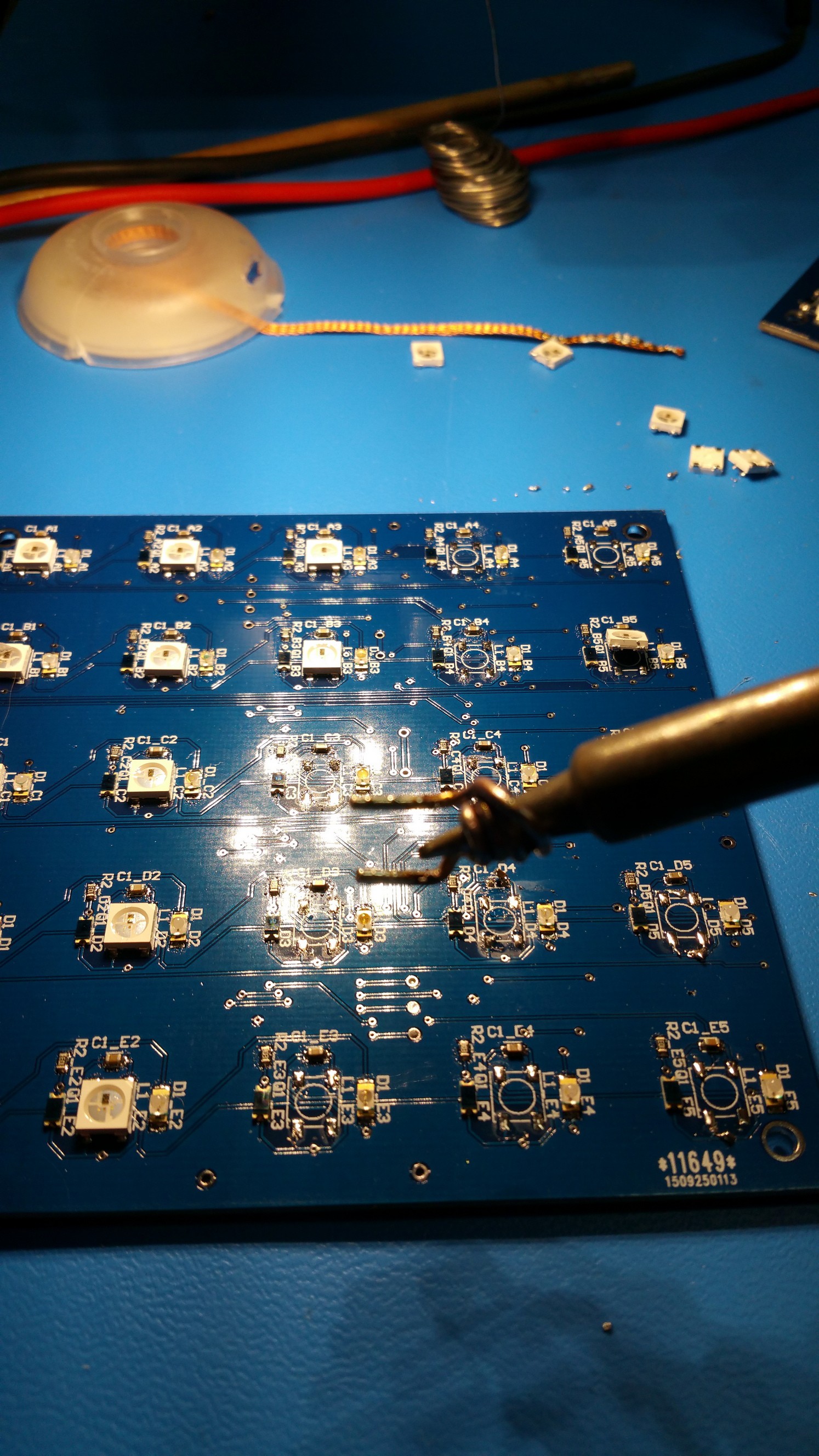
This worked pretty well, and i was able to save many LEDs and get them turned the right way. Luckily, the WS2812 has reverse voltage protection, and I hadn't been using the 20A power supply to test them! The thing that clued me in to them being backwards was that my power supply was going into short circuit protection when I powered the board. My vintage adjustable bench supply can only put out an amp, so it tends to be picky about overcurrent.
Even after fixed the LEDs, it was still going into overcurrent protection, so something else was up. I then discovered how DirtyPCBs can be so cheap. They do a reasonably good job, but sometimes there is an etch error, and they fix them by hand if the E-test catches them.

Almost every single board had some kind of small repair like this, inked over in blue sharpie. There were a few minor power shorts that they did not catch and fix. I learned a trick as an intern at iRobot for fixing a power plane short on a populated PCB. if it's a small enough short, simply hook up to a nice big supply at the rated voltage. I had purchased a 5V 20A supply for this project (back when it was going to be 729 LED cells instead of 225). This power supply did the job in short order. They mostly turned out to be a ground trace caught on the edge of the Vcc plane. Freshly un-shorted and cleaned up, ready to repair


There were also a few cases where the solder mask relief around a pad went a hair to far and exposed the copper of a power plane. Since the footprints of the IR bits were a tad too small, I ended up with a few shorts from this too. With all the PCB errors fixed, I can finally get on to the code!
Discussions
Become a Hackaday.io Member
Create an account to leave a comment. Already have an account? Log In.