 ThunderSqueak
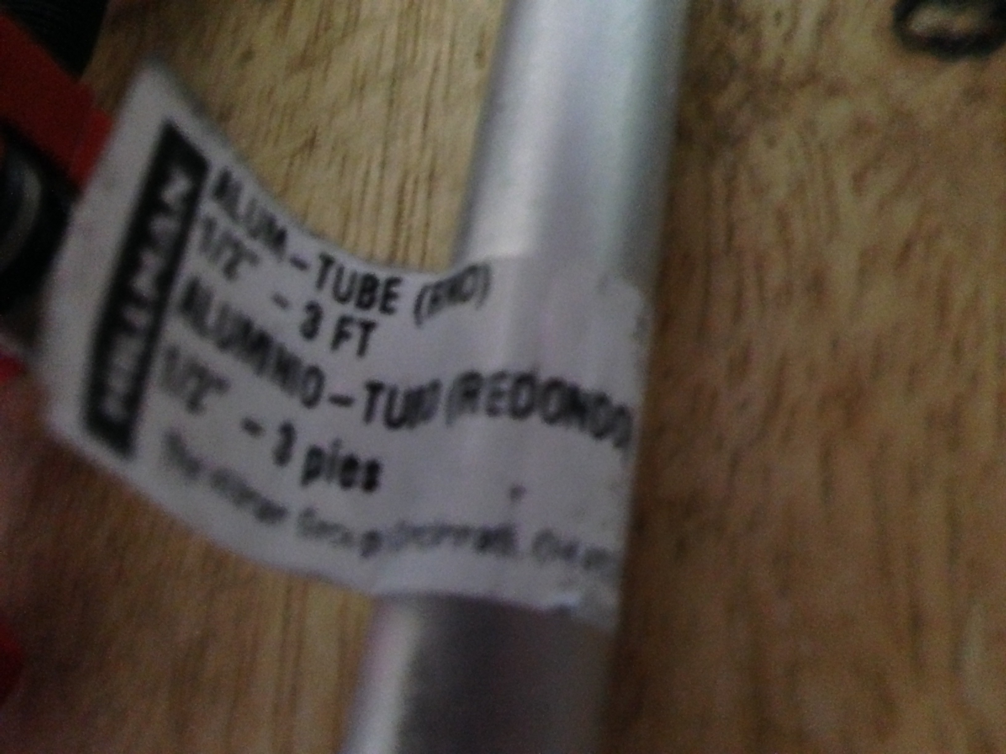
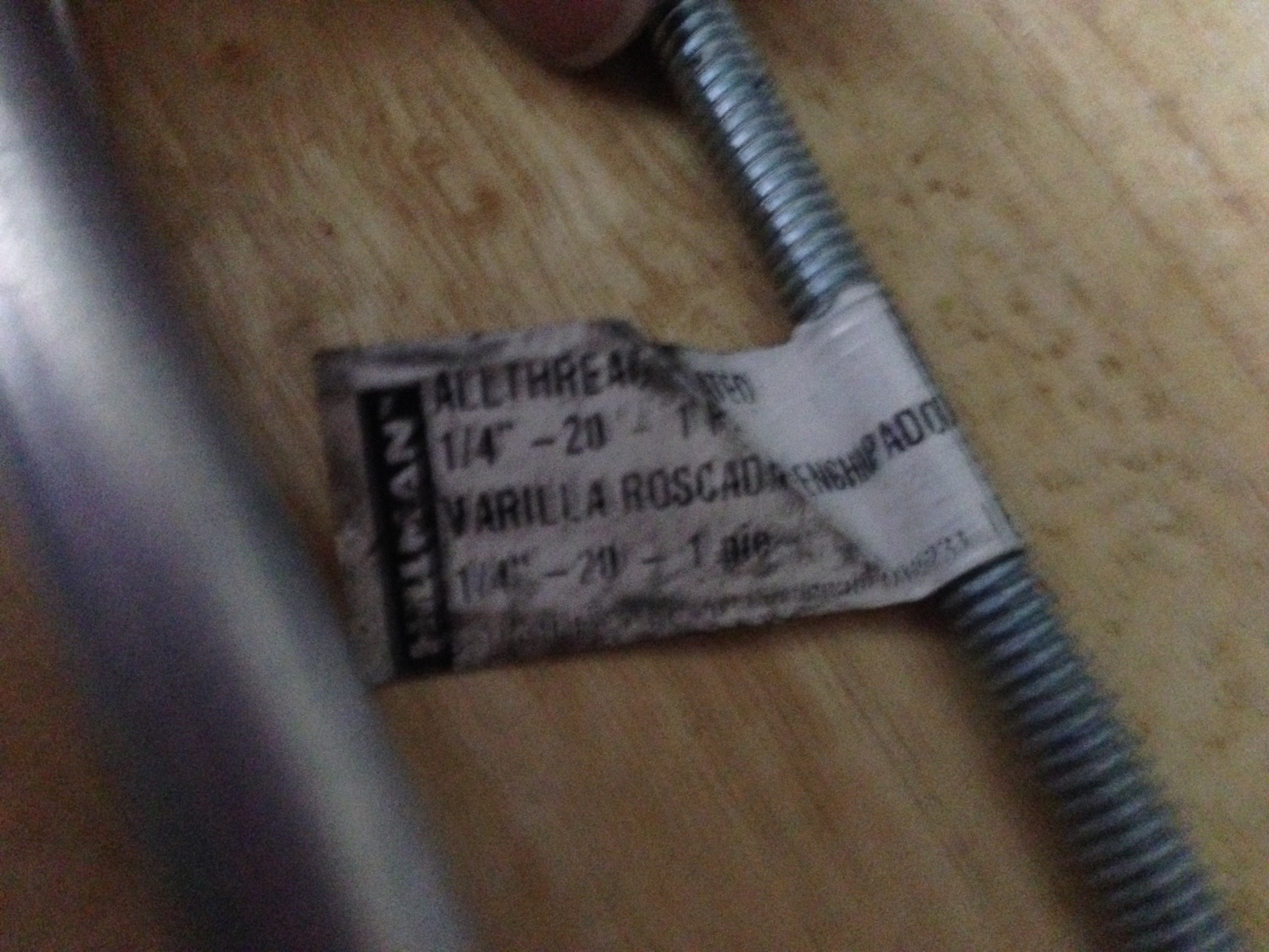
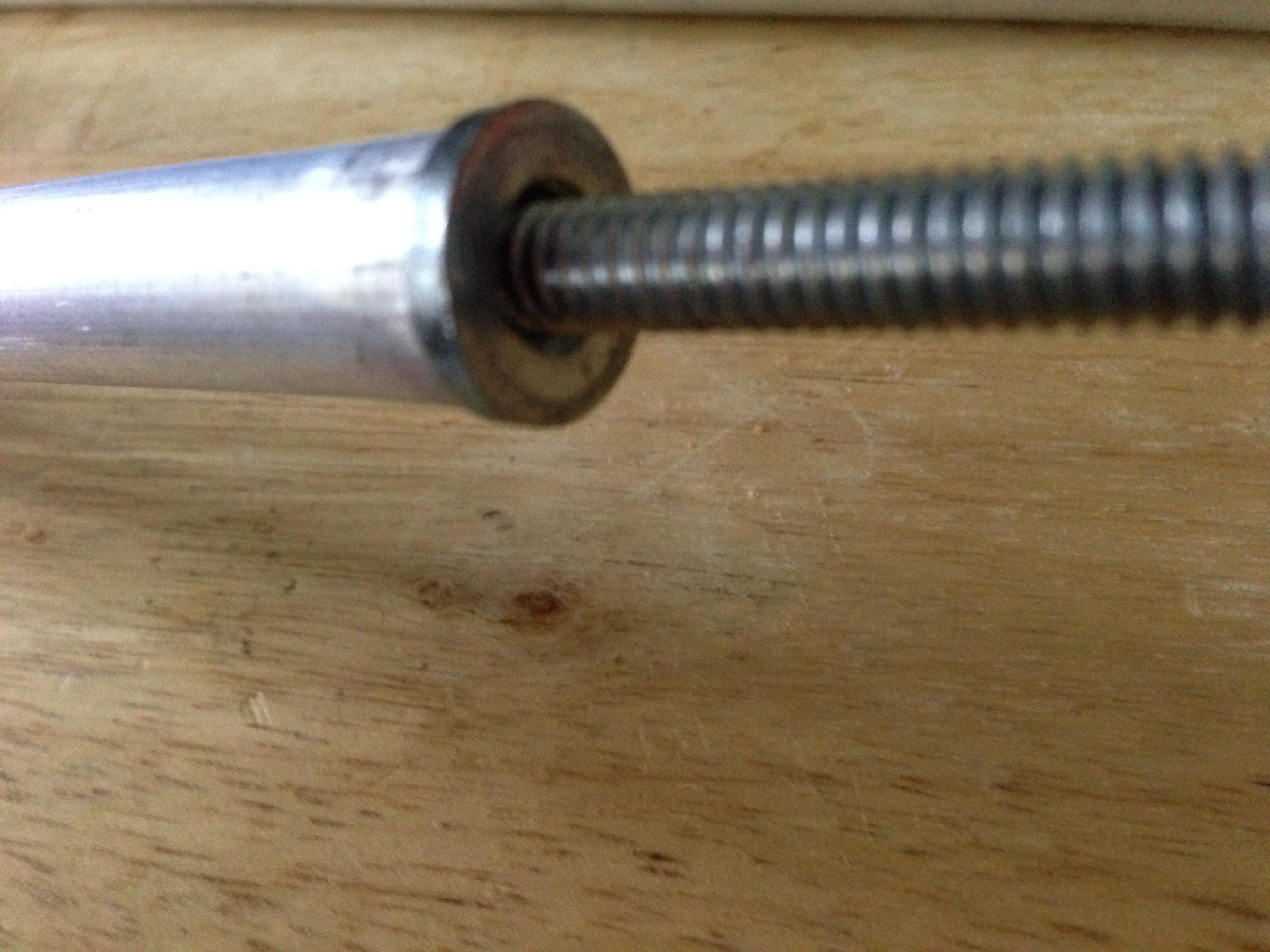
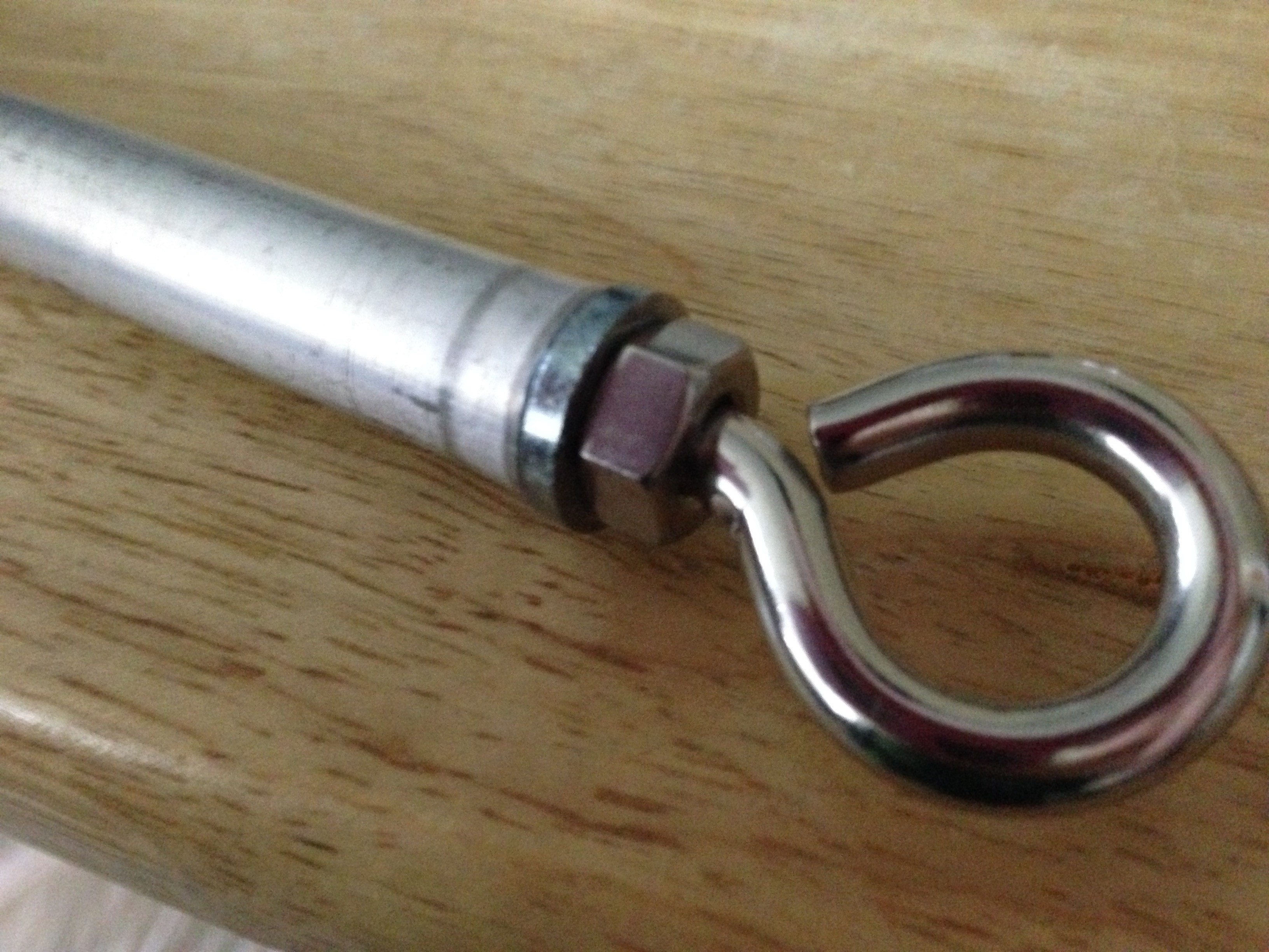
Today during my lunch break I was thinking about linear motion, linear actuators, and linear servos. Many of them are very expensive and heavy. After some thought, I may have a solution... using a half inch aluminum pipe, 1/4"-20 all-thread rod, some threaded furniture inserts that are 1/4"-20, an eye bolt 1/4"-20 with matching nut, and a peice of 1/4" angle aluminum. Along with some 3D printing it should be acceptable for light duty work.
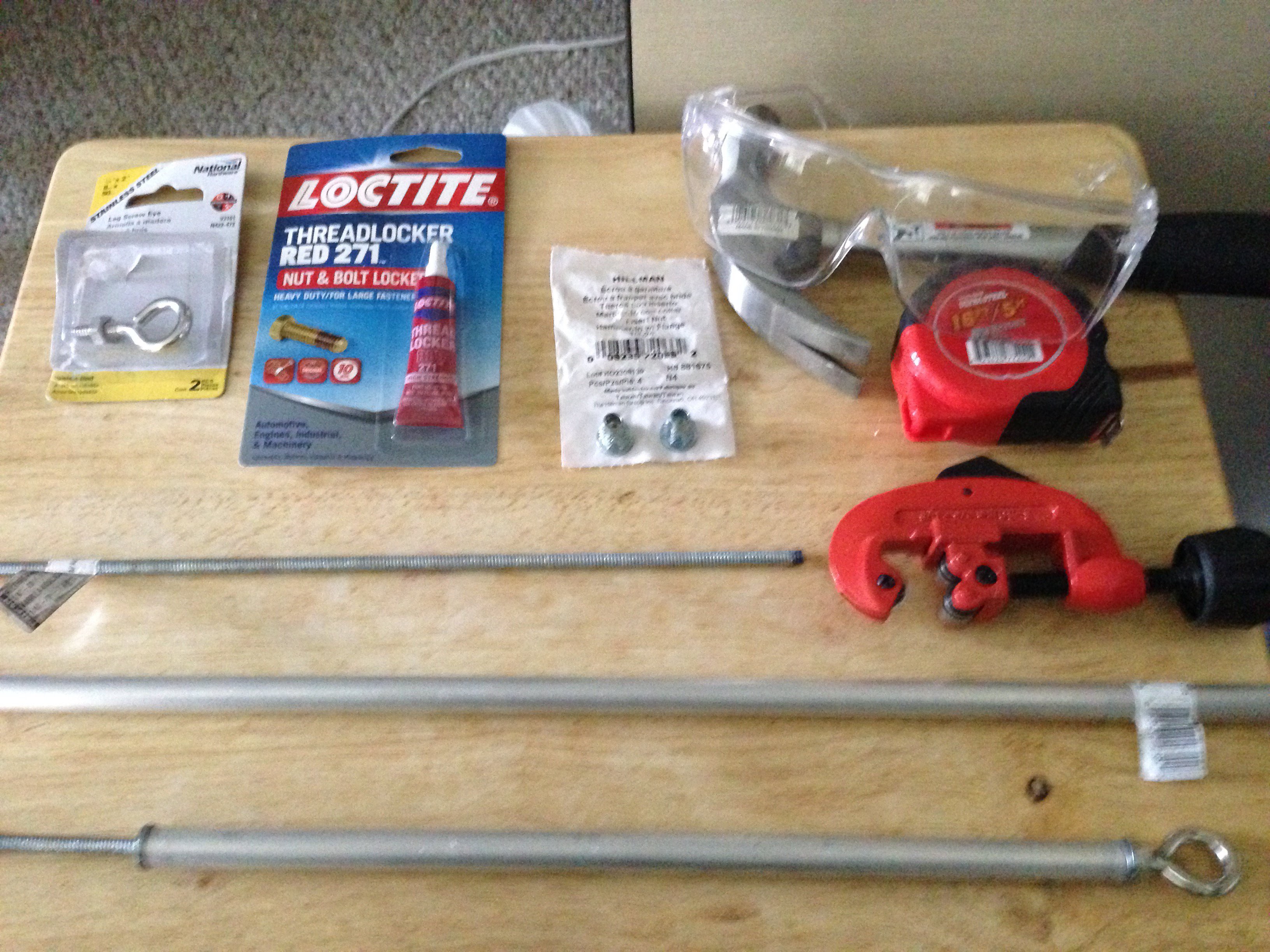
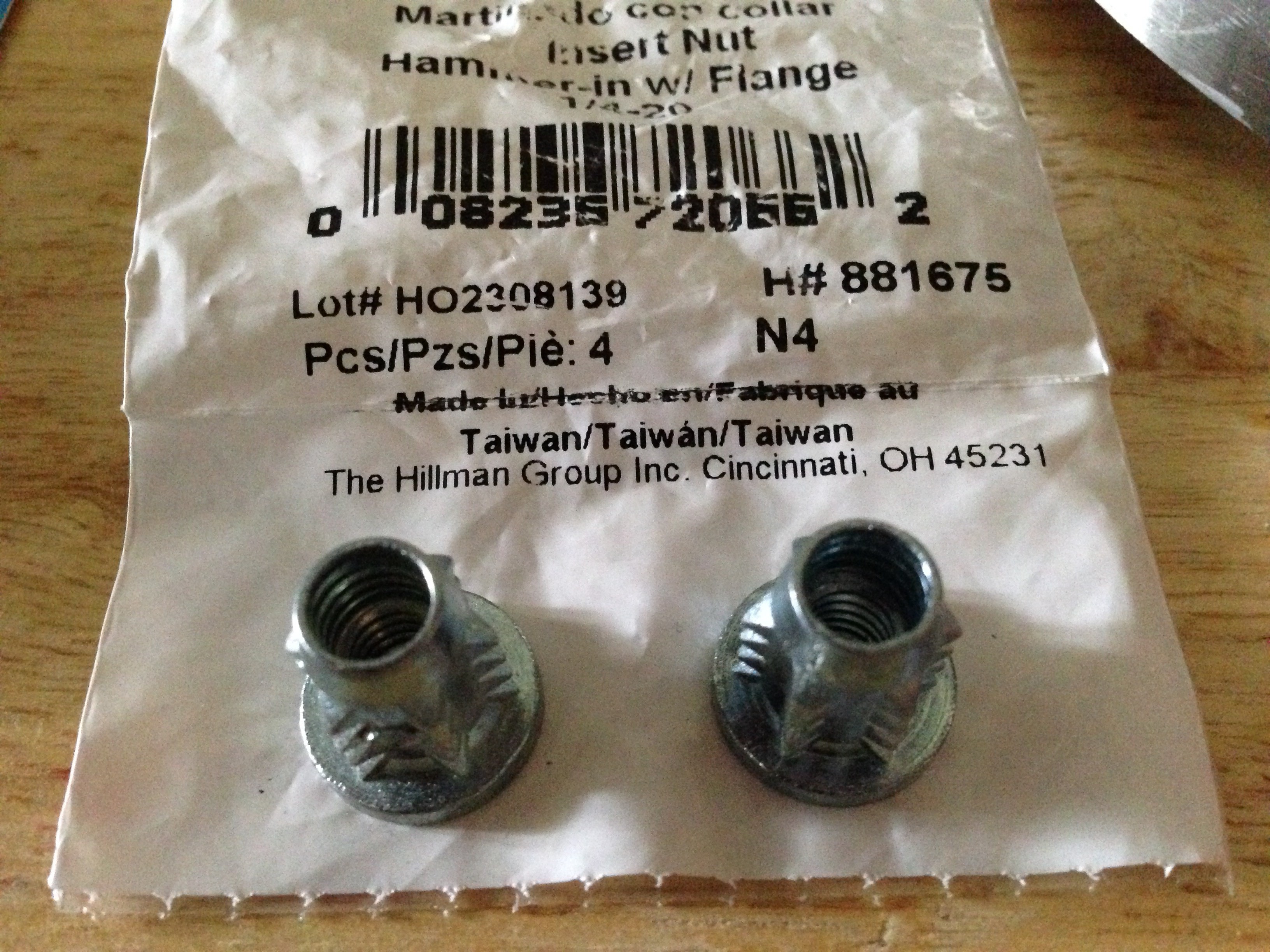
wearing some eye protection, I hammered in the inserts into a piece of pipe cut at 12", then simply threaded in the eye bolt and the all-thread. the locktite is for the eye bolt. after I finalize the design. Without the motors, it should come to about 6 dollars per linear actuator. Since these are not meant to handle a lot of stress, the motors should be able to be placed in line with the all-thread rod and coupled directly to the motor shaft. 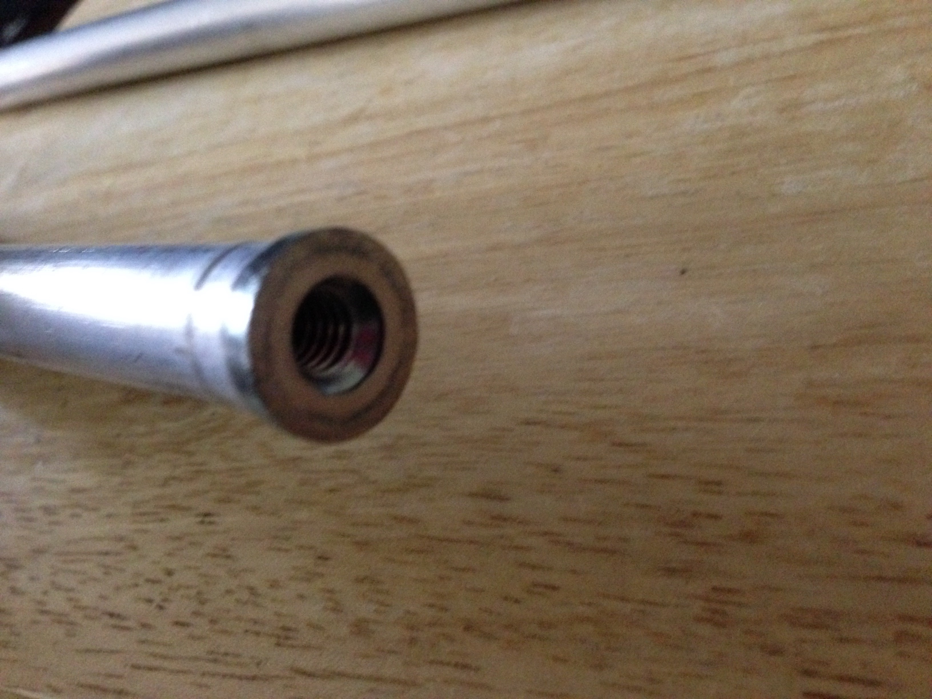
When my 3D printer is back and functional, I will print out the motor mounts and attach the two angle iron sides. I picked angle iron so that there is a "slit" along each side, this will allow me to put in a screw near the top and bottom of the piece above and add some switches to designate the end points should be necessary.
This is a quick rough sketch of the initial idea, the black "rails" are capped on each end with some 3D printed parts. Any limit switches can then be easily fixed to the sides of the rails by drilling and tapping the angle iron.
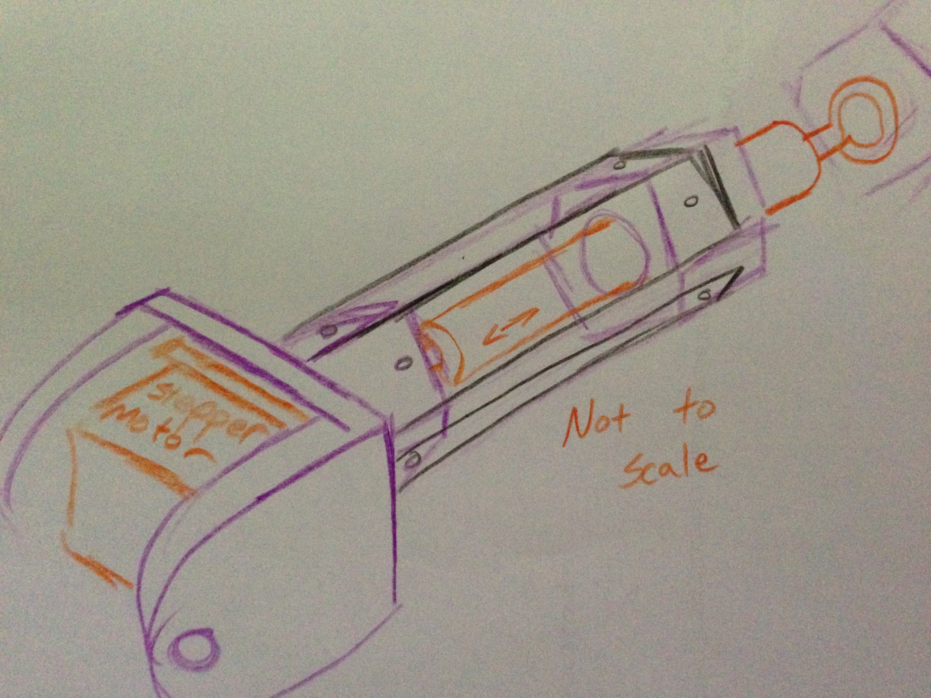
Stepper motors, servos, or DC motors could be used depending on which mounting solution is chosen for the motor side of the 3D print.
cheers
Discussions
Become a Hackaday.io Member
Create an account to leave a comment. Already have an account? Log In.