 Nevyn
NevynThis project started at the beginning of the year when a Kickstarter campaign delivered the Oak to my home. The Oak is a ESP8266 board based upon he ESP12 module. This makes it an ideal low cost board allowing an application to read from a number of sensors and sending the data to the Internet.
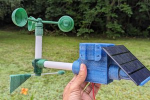
A few hours research built up the list of sensors and the concept of the modular weather station was born.
Mind maps offer an ideal pictorial way of representing the project goals:
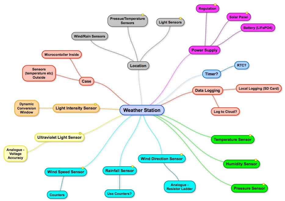
The project concept is born, weather sensors, meet the Oak.
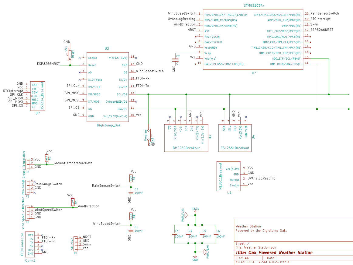
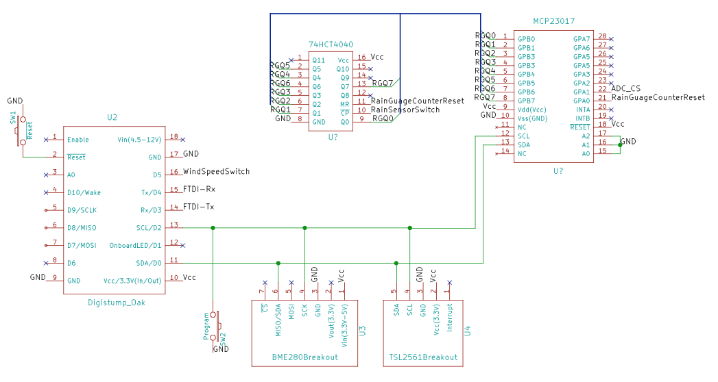
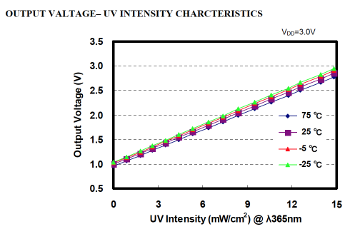
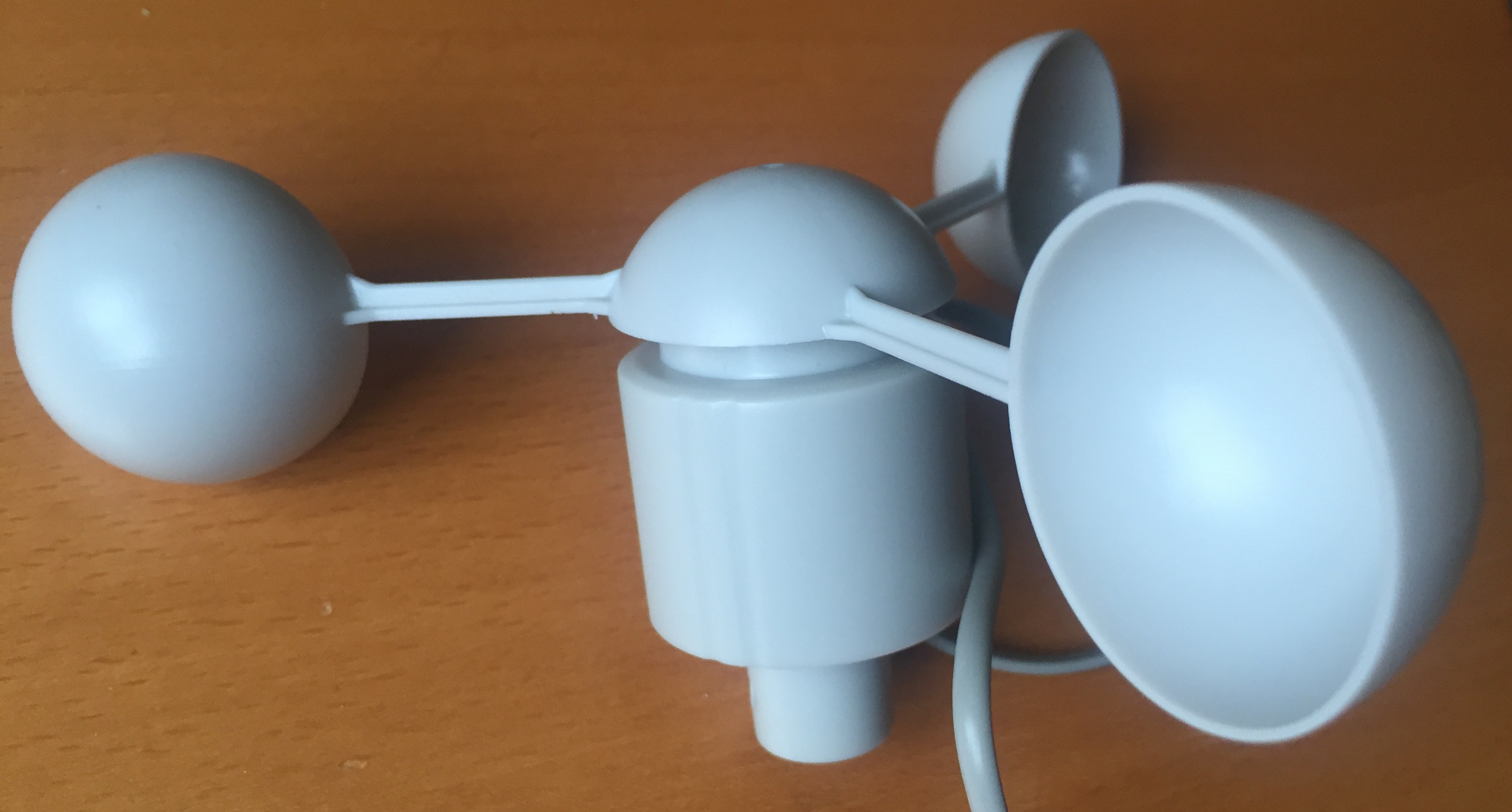
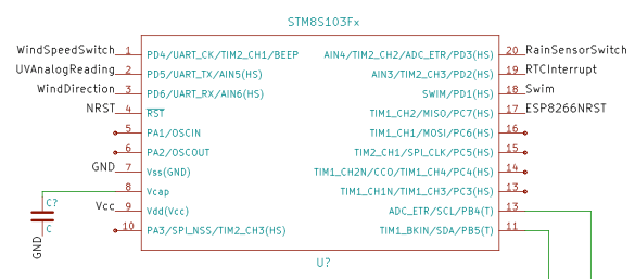 The STM8S should be able to take over the reading values from the following sensors:


 JP Gleyzes
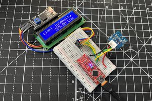
 ElectroBoy
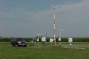
 sparks.ron
Perfect, no problem =)