 will.sweatman
I chose one of these scales to hack. It turned out that the microcontroller, ADC and LCD controller were all in one "black blob" IC. The entire balance consisted of the black blob IC, EEPROM to store the firmware, raw glass LCD and the load cell. So the only way I could get any weight data off the thing was to decode the multiplexed signals going to the raw glass LCD.
This was not easy. There can be no DC on a raw LCD. So the signals are multiplexed, and consist of four levels - 0v, 1v, 2v and 3v DC. Each level is two ms long, and the entire signal is 16ms long. There is one unique signal going to each of the 16 LCD pins. They are timed so there is never a long lasting DC voltage on any of the pins.
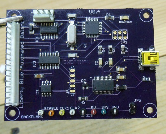
I started by taking what they call a "backplace" signal and used it for timing. The backplane signal is just like all the others - a 16ms long signal consisting of 8 different voltage levels, each being 2ms long and consisting of 0v, 1v, 2v or 3v. The backplane signal never changed, and had one single 3v pulse. I used this for timing. It was fed to a PIC to develop a sharper timing signal, and this was fed to an Arduino to decode everything else.
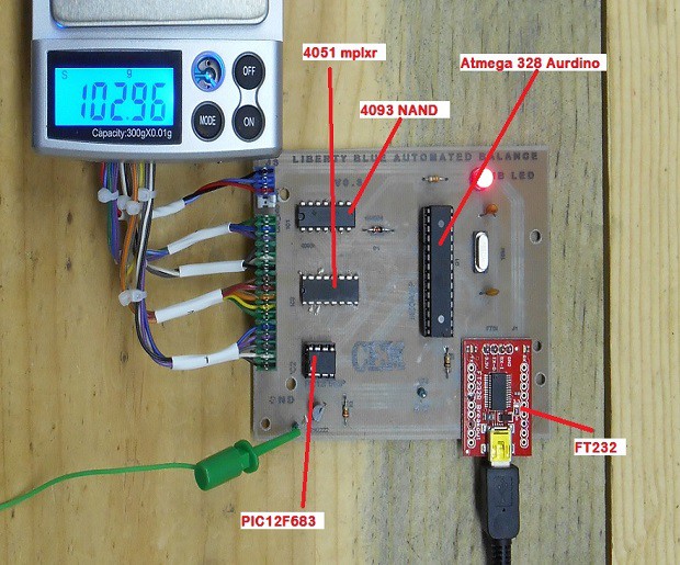
Each signal was fed to the arduino adc through a 4051. The arduino treated 0v and 1v and a LOW and 2v and 3v as a HIGH. These values were fed into an array, and used as digital representation of the signal that was on the pin. Then a look-up table is created to match the value in the array with the digit value on the display, and this data is pushed to the serial port. BAM!
Here is my story.
*****NOTE - This project is not complete. I still have to finalize the enclosure. Once this is done, I will post pictures, the Eagle files and source as the final update. There will be little change to what is already posted in the links below.*******
Update 02/25/2014
SMD boards are in. I populated one and it's working well. I made a video of it working.
Update 02/08/2014
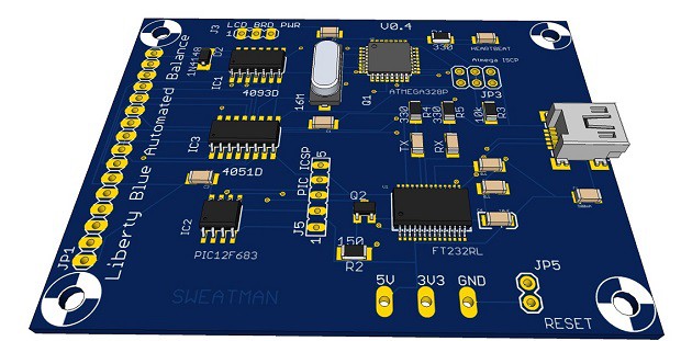
I finally got something I can ship for testing. It will be there next week. The schematic and source are all finalized. I moved to the 12F683 for the PIC. It's small, needs no external circuitry and costs about a buck fifty. The entire cost of what is shown is only $30. I made another quick video of it working, but it operates the same as before (I fixed a small bug in the forth place digit). It just looks a lot neater. I've got the render of the SMD version of the board (see image below), which is small enough to fit inside the balance housing if needed. We would just have to print out some supports to expand it. Now is the time to start thinking about a housing.
This rendered image was made with Google SketchUp along with the popular EagleUp plugin for Eagle CAD. The circuit was designed in Eagle.
Update 01/29/2014
First field test of the balance. I added 1 mil, tared, added 1 mil, tared and added 2 mil.
Update 01/21/2014
I've got a protoboard made and the code finalized. See video and image below. The schematic is still a little sloppy - I'm in the process of moving the Arudino components over to the main board. Once this is done, I will share it for review, then send it out to a pcb boardhouse.
When you watch the video, you will notice that the serial out no longer lags, nor does it miss digits as before. I found that the Arduino was running WAY faster than the signals off the balance display. Because of this, I was missing data as I was cycling through the code. Now, I run the code to get some data, and then wait for the next pulse of the timing signal. The timing signal pulse is based off the display signals, and is roughly 60Hz. I do this repeatedly, so now I don't miss any data and the updates are nearly instantaneous. It could not work any better.
There is a DOWNLOADS section below the new video. There you will finds links to the complete source code and project files.

Downloads
- LB Auto Balance V0.1 TXT
- LB Auto Balance V0.1 ARDUINO
- LB Auto Balance V0.1 PDF
- PIC source TXT
- PIC MPLAB files
- VB6 files
- LB Auto Balance VB6 program exe
Update 01/07/2014
I'm now getting weight data printed to a serial console. I'm just printing characters for demonstration right now, as seen in the video below. You will have to expand it to full screen in order to read the console data. Next step is to whip up a vb6 program that can take the serial data and log the weights. This will be the next update.
The schematic has changed a little. I was able to get rid of the LM339 and do it's job in the firmware. I'm also controlling the 4051 multiplexer from the Arduino instead of the PIC. The PIC is still needed for the timing, however I changed the way it's doing this. Instead of generating a timing pulse for each bit, I'm generating a single pulse for the very first bit and using a delay to get the others. Also, I found that I did not need all eight bits to uniquely ID each digit. I only need four bits, so I'm getting just the even ones. This lightens the overhead, and the code runs much faster this way.
An overview of how this works -
The raw LCD data has four voltage levels - 0v, 1v, 2v, and 3v (seen in purple). You can see all of these signal in the 'Links' section below. I'm using the ADC of the Arduino to assign the 0v and 1v to a LOW bit. And the 2v and 3v to a HIGH bit. Like this:
Because the raw LCD data is repeating, I need to time when I take the measurement of each bit. This is where the backplane, AND gate, and PIC come into the picture. A backplane signal from PIN1 of the display (seen in yellow in the scope) is being fed into a CMOS AND gate. This signal never changes, and contains a single 3 volt peak that is 2ms long and appears every 16ms. The output of the AND gate is the clock signal that I'm using for the timing (seen in blue). Because it's 2ms wide, the same length as the raw LCD signal bits, I cannot use it the way it is. The PIC takes this signal and produces a sharper 500us signal (seen in green). So now I can say:
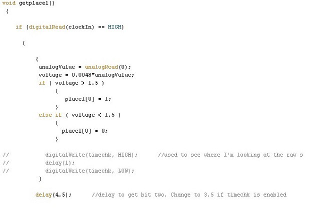
When timing pulse from PIC == 1
{
get bit data
delay
get bit data
delay
}
I do this four time, to get four bits, and put them in an array, where they'll later get decoded into a single numeric digit.


Update 12/29/2013
Now that I have the 19 total signals from the display fully decoded, I can think about how to go about processing them. There are two ideas - process the analog signals or convert the signals to binary, and then process them digitally. I decided on the latter because the signals are long, about 16ms, and there are only 4 voltage levels to deal with. I found that if treated the 3 and 2 volt levels as 'high' and the 1 and 0 volt levels as 'low', I could develop a unique binary marker for each of the 19 signals.

The lower signal (purple) is the raw signal coming of the LCD display (pin 7) for place 1. This decodes to 'zero'. The yellow signal above is coming off the 4051 multiplexer. I'm using the 4051 to choose between the 8 different signals I need to read from the LCD. I'm using a PIC to generate the timing signal in blue. This is based upon a clock signal that is made from one of the back-plane signals (see links section below). The green signal is the output of the comparator. This is a unique, binary representation of the raw 'zero' signal in yellow. The next step is to use an arduino (or some other processor) to convert the comparator output to something a PC can read.
