 Hari Wiguna
I found the 4x4x4 RGB cube very rewarding to build so I'm moving up to 8x8x8. I decided that I'm not ready for RGB version yet, so I'm only building single color.
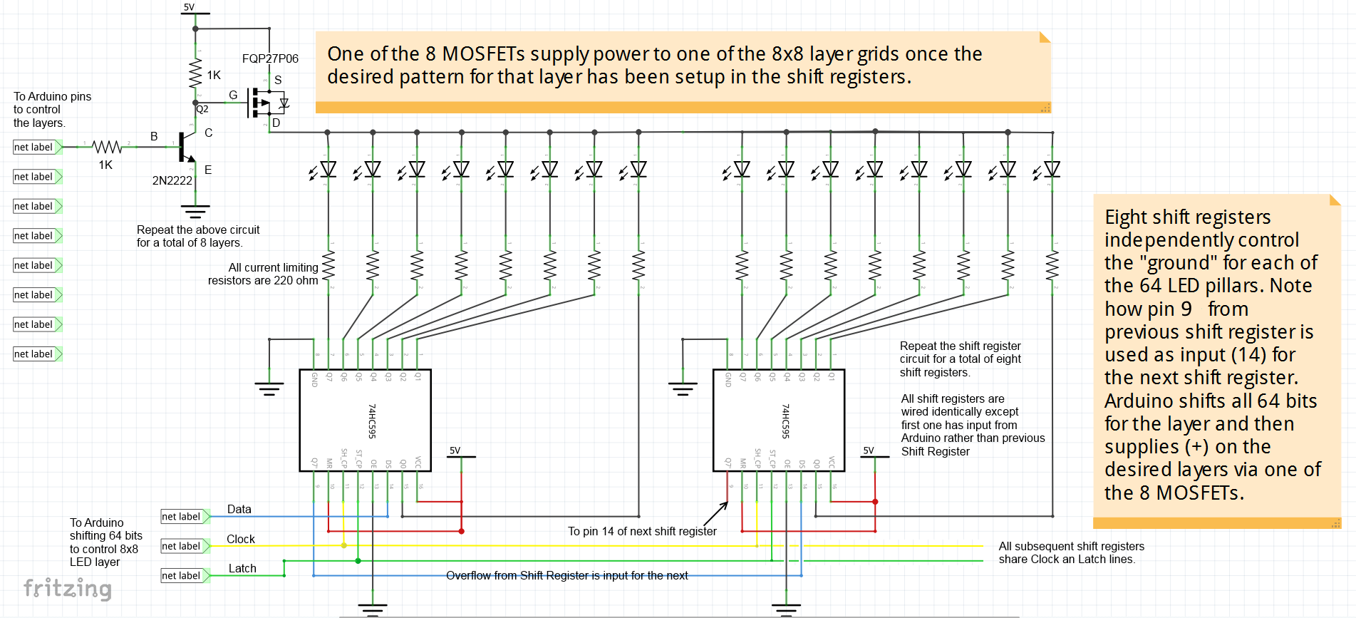
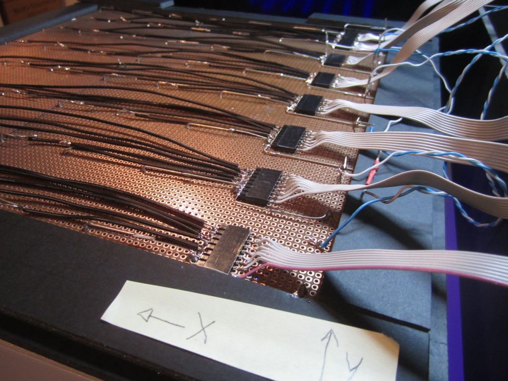
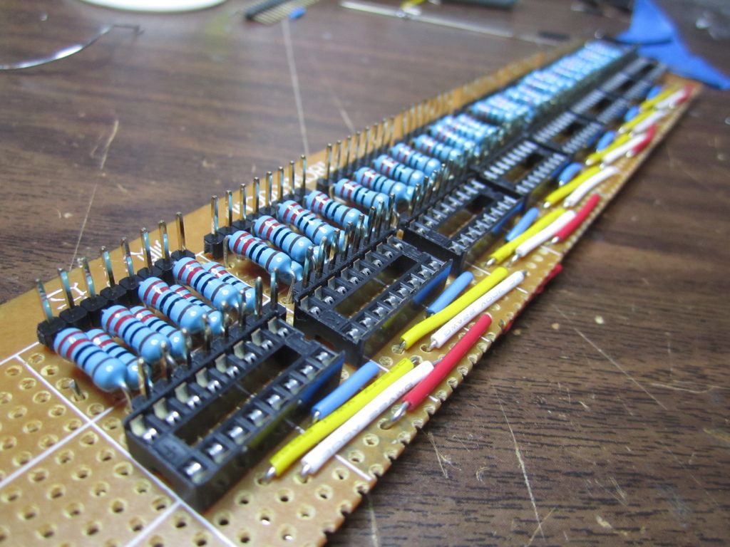
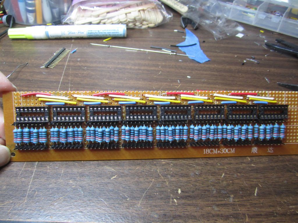
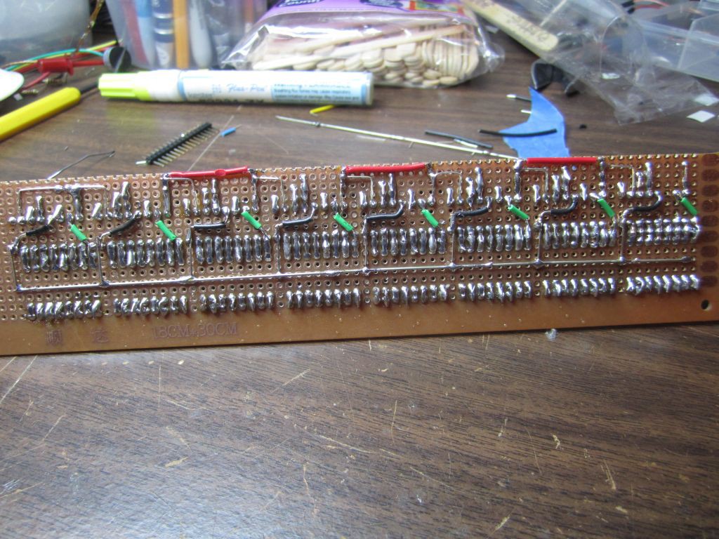
WIRING:
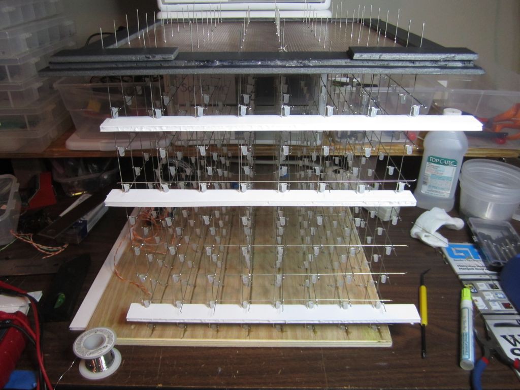
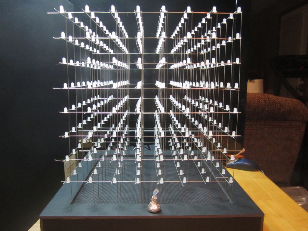
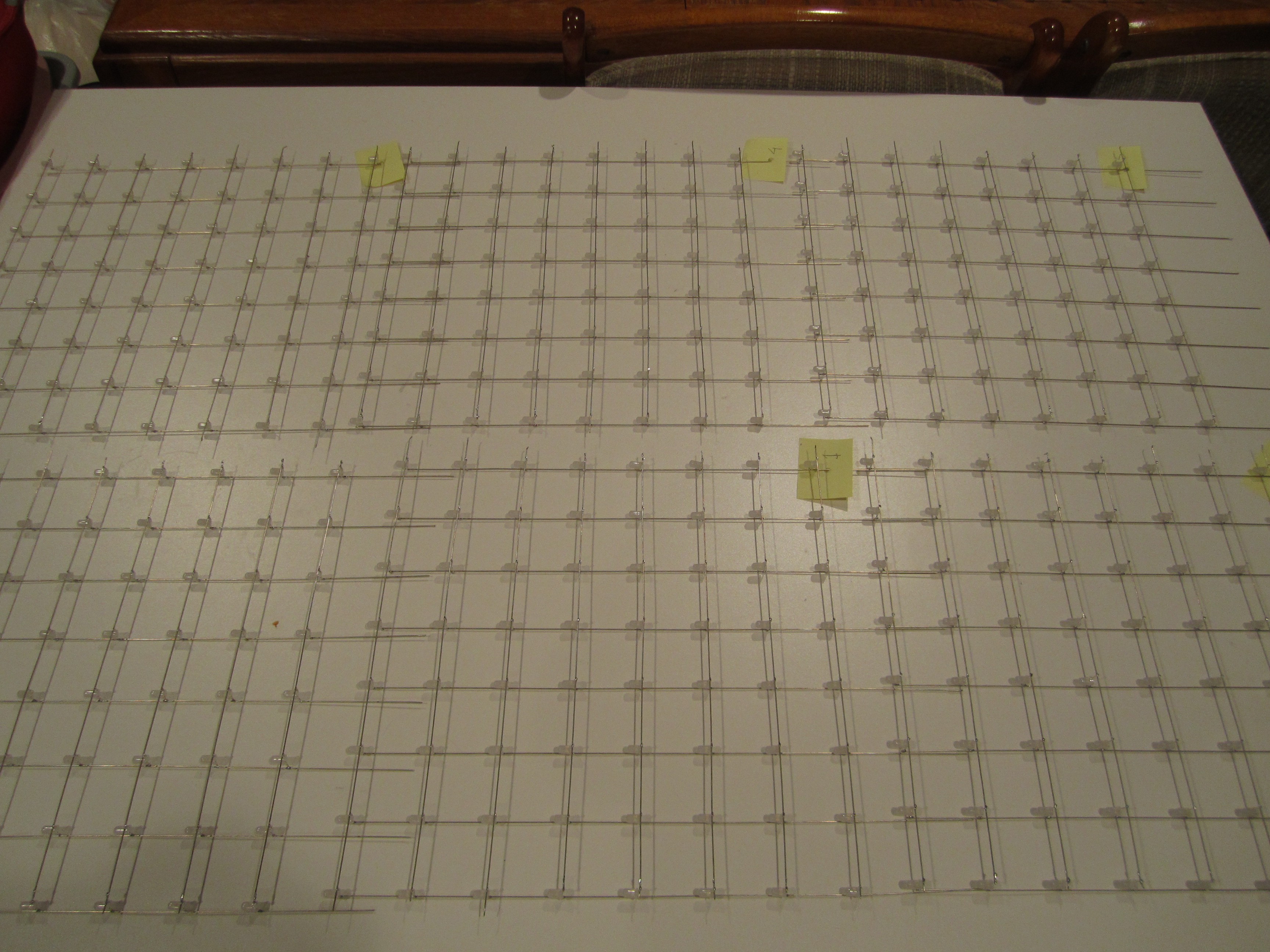
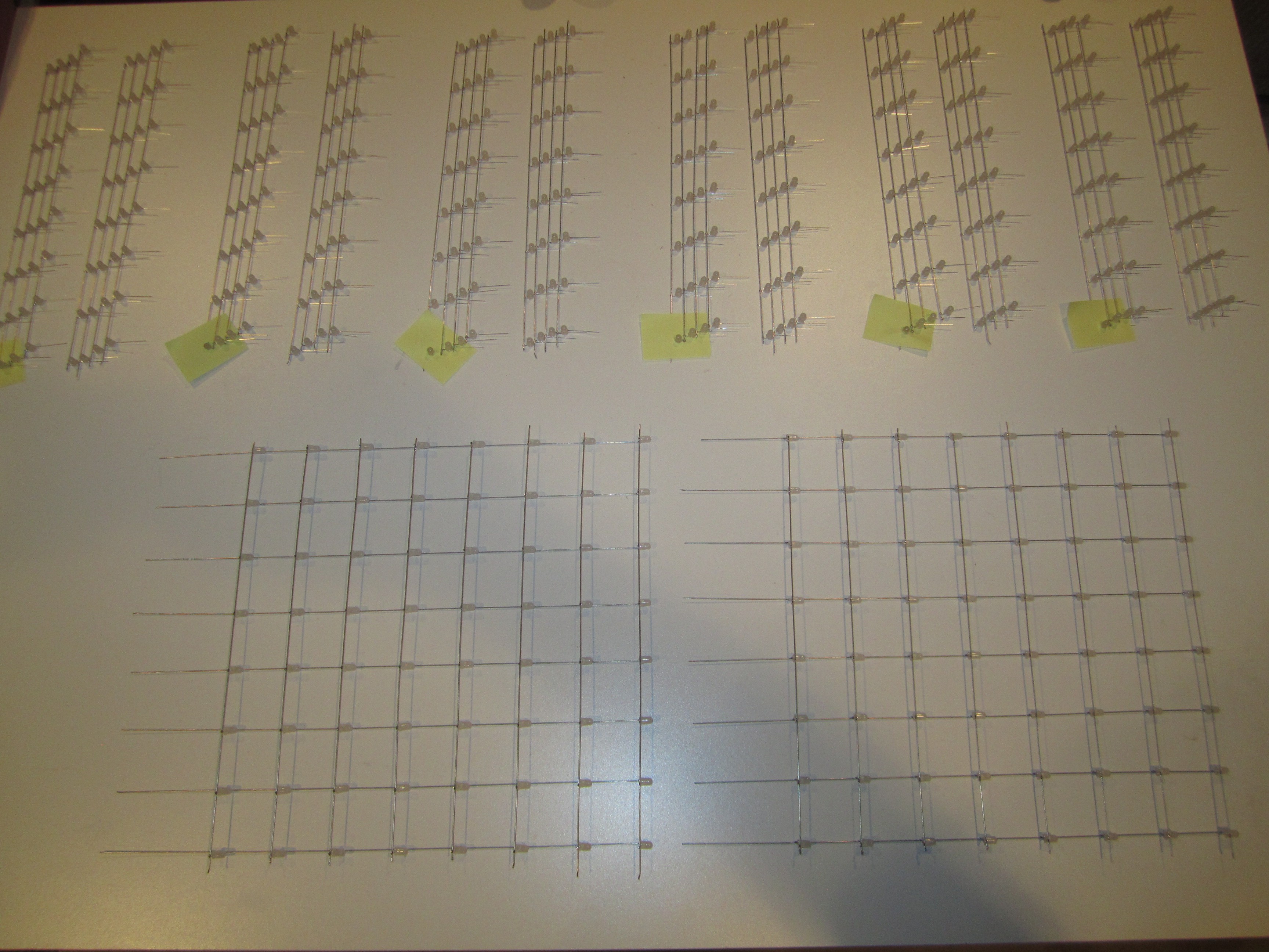
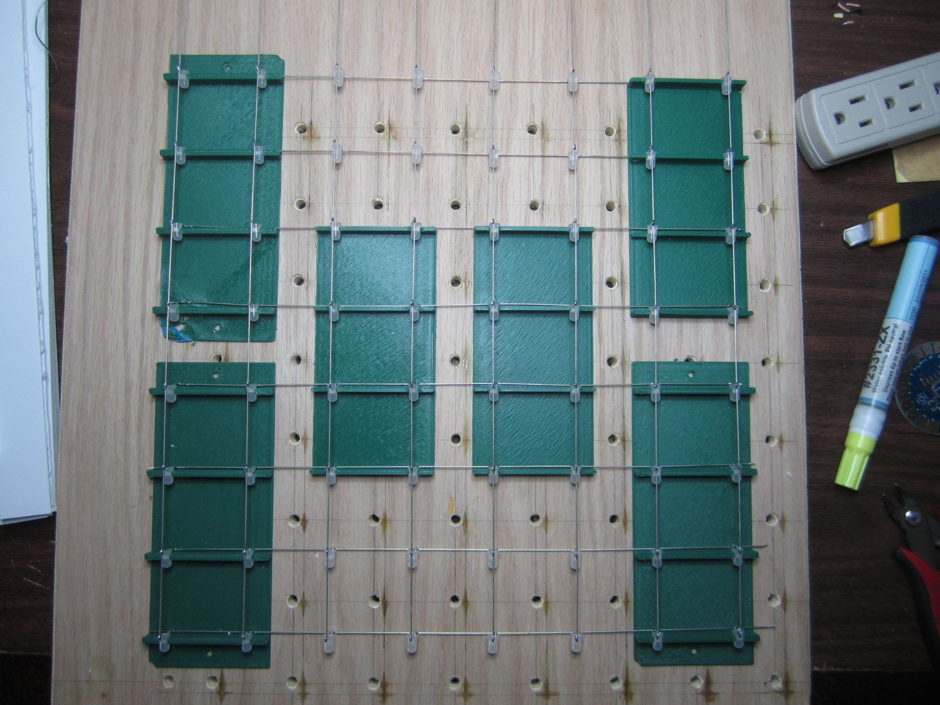
Electrically, the cube is made up of 64 pillars containing 8 LEDs each.
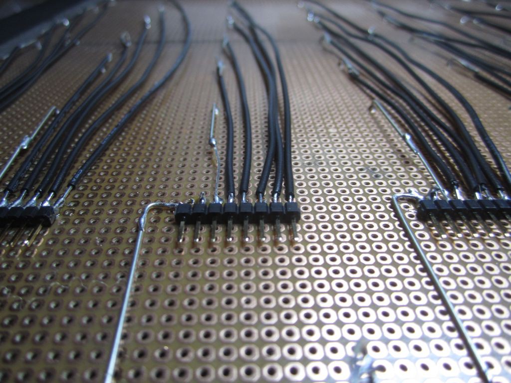
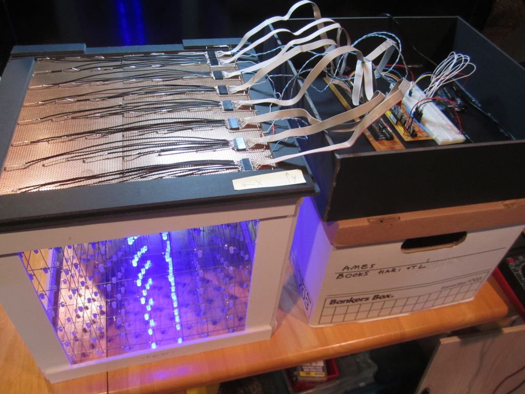
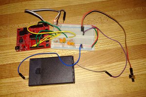
Eight 8-bit shift registers (74HC595) supplies the GROUND for those pillars.
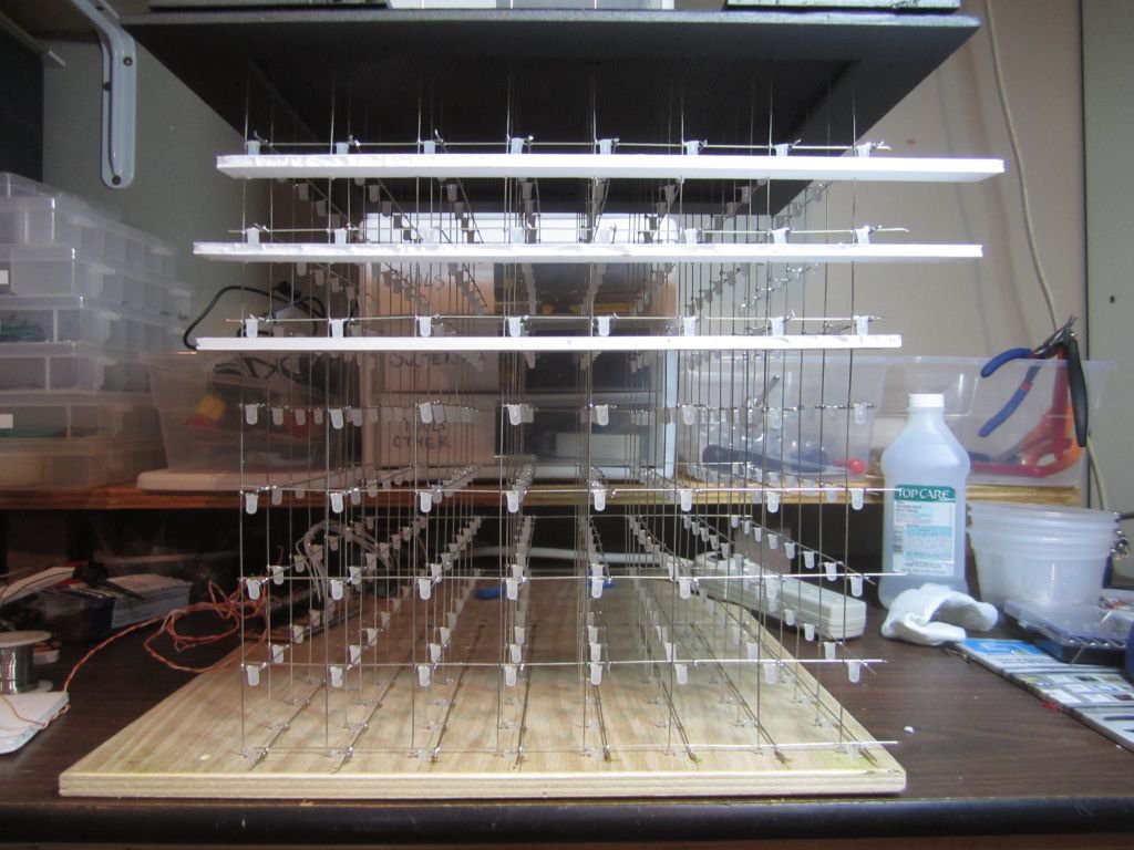
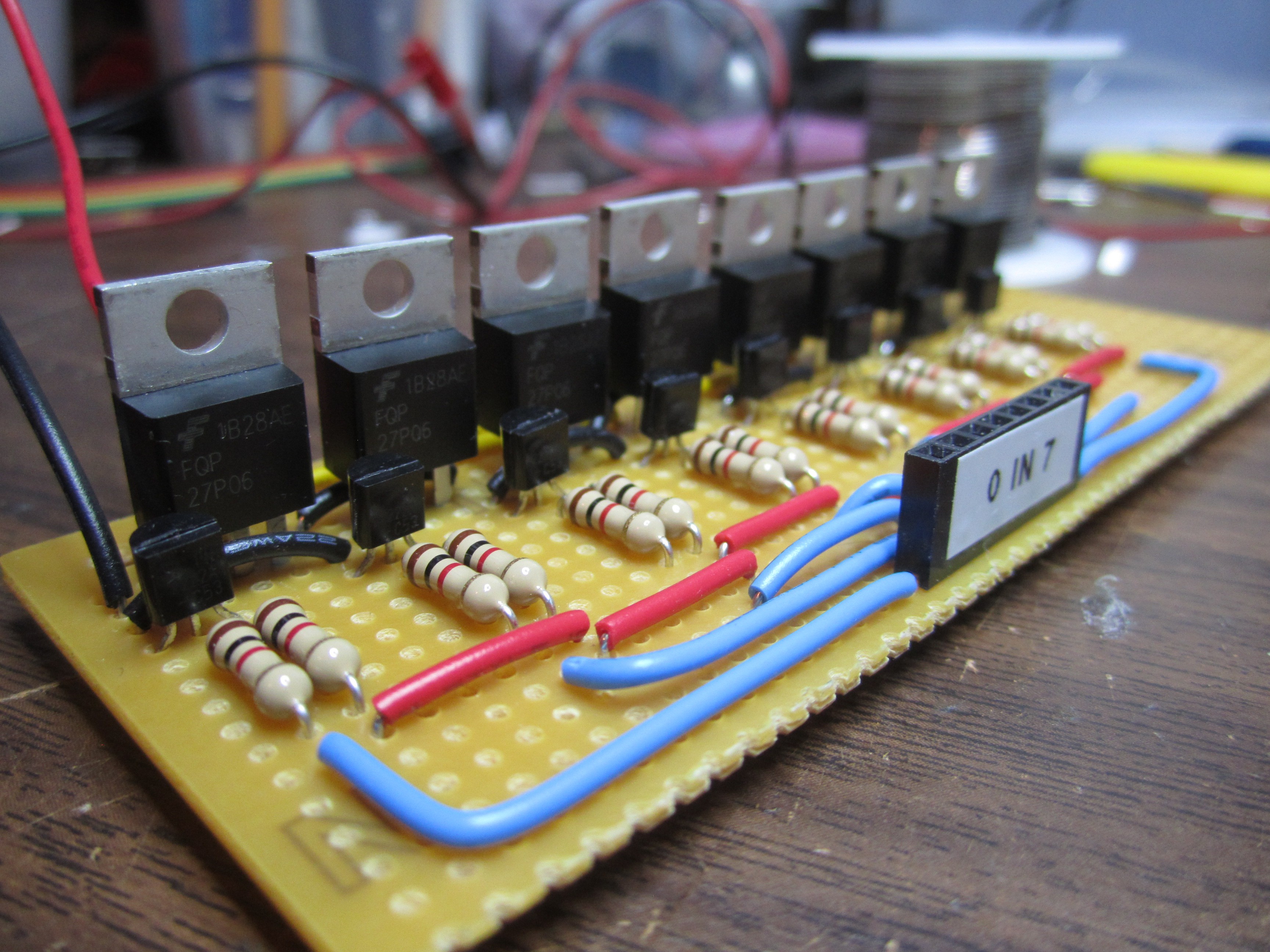
Each layer of the cube shares a common +5V switched by a P-Channel MOSFET, for a total of 8 MOSFETs.
HOW IT WORKS:
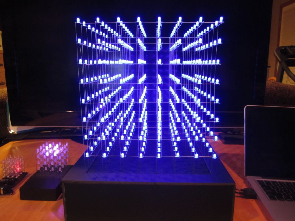
At any time, a maximum of 64 LEDs of ONE particular layer would be all lit up. Quickly setting up which of those LEDs on that layer should be on and then repeating that for the other layers, gives the illusion that we can individually control every individual LED.
LESSONS LEARNED:
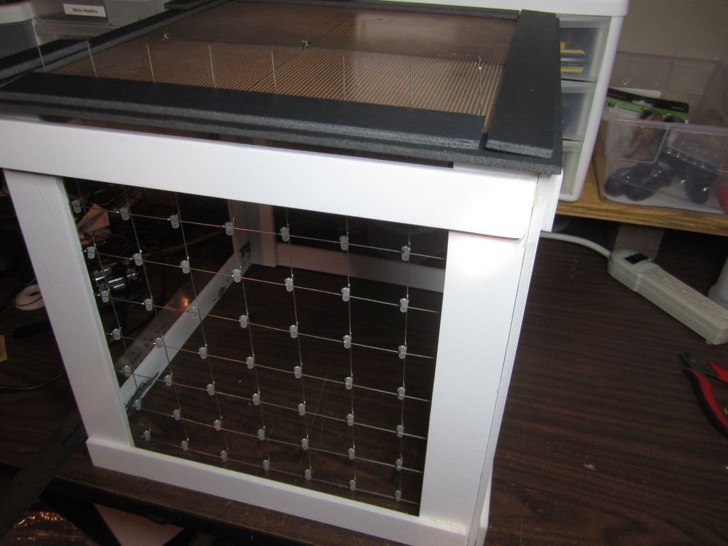
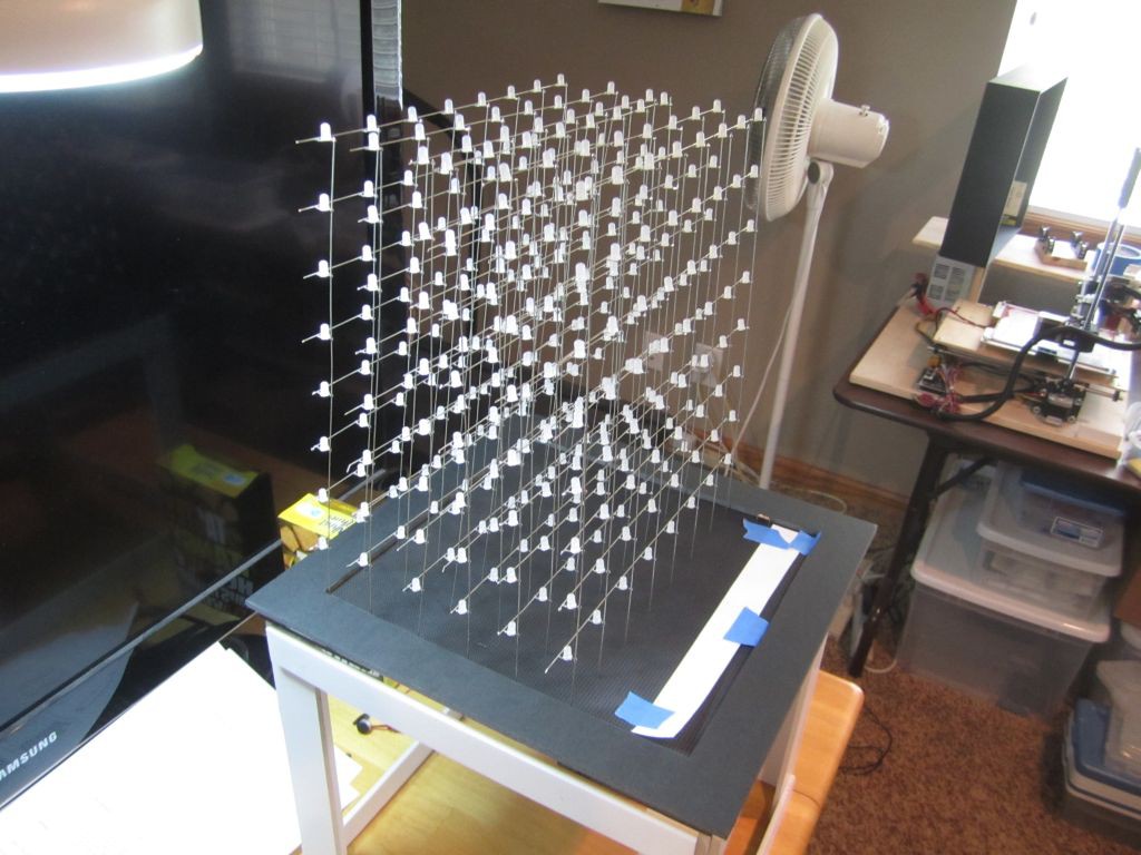
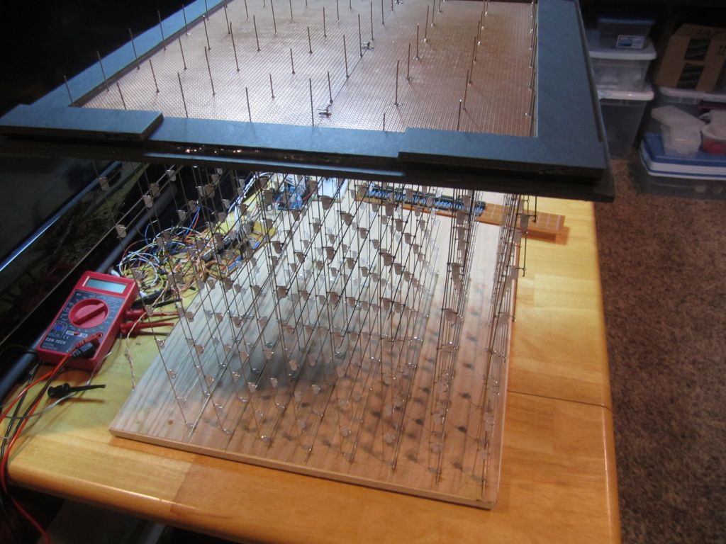
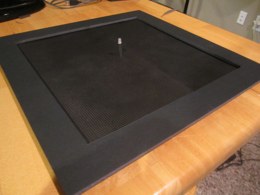
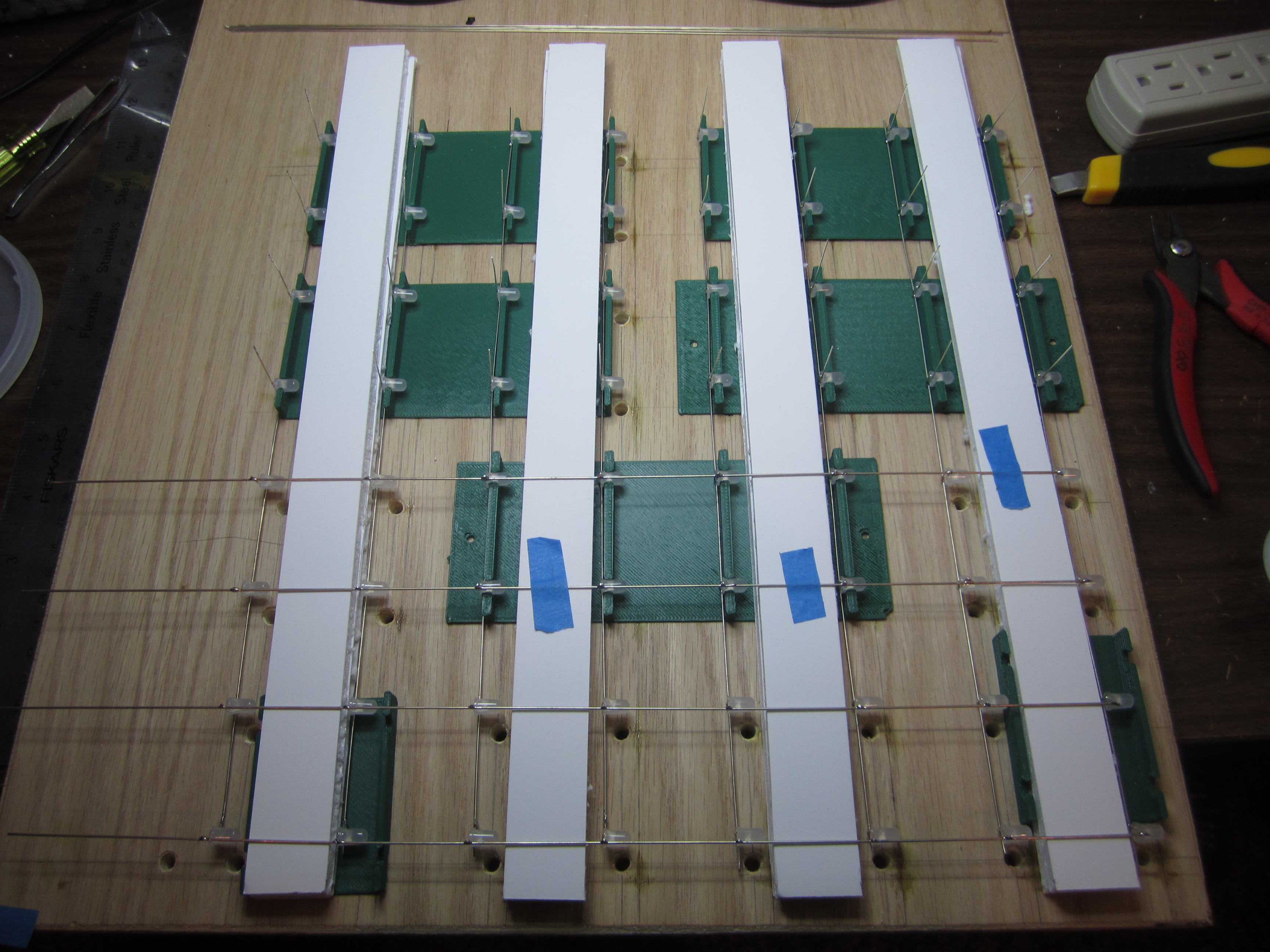
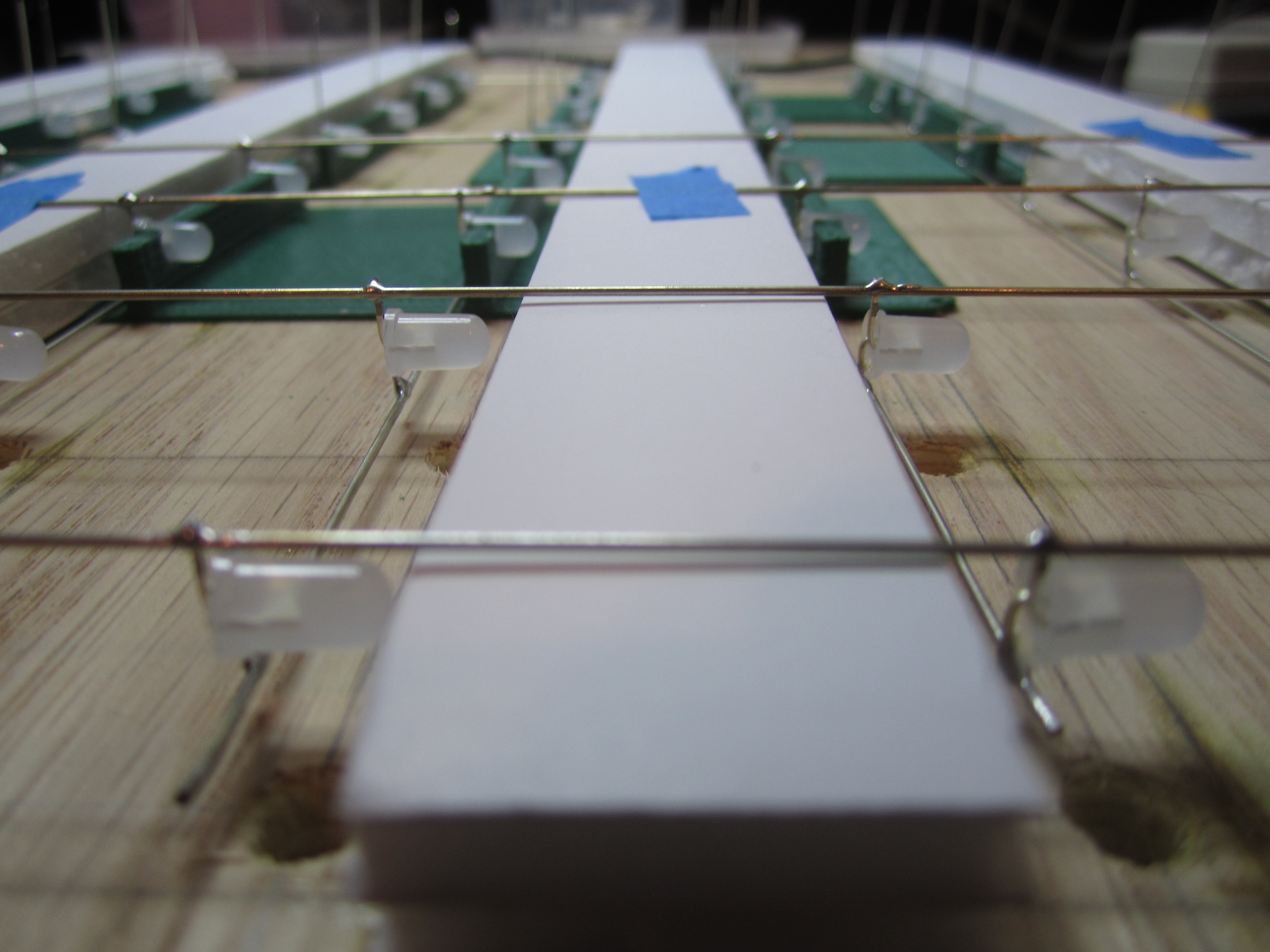
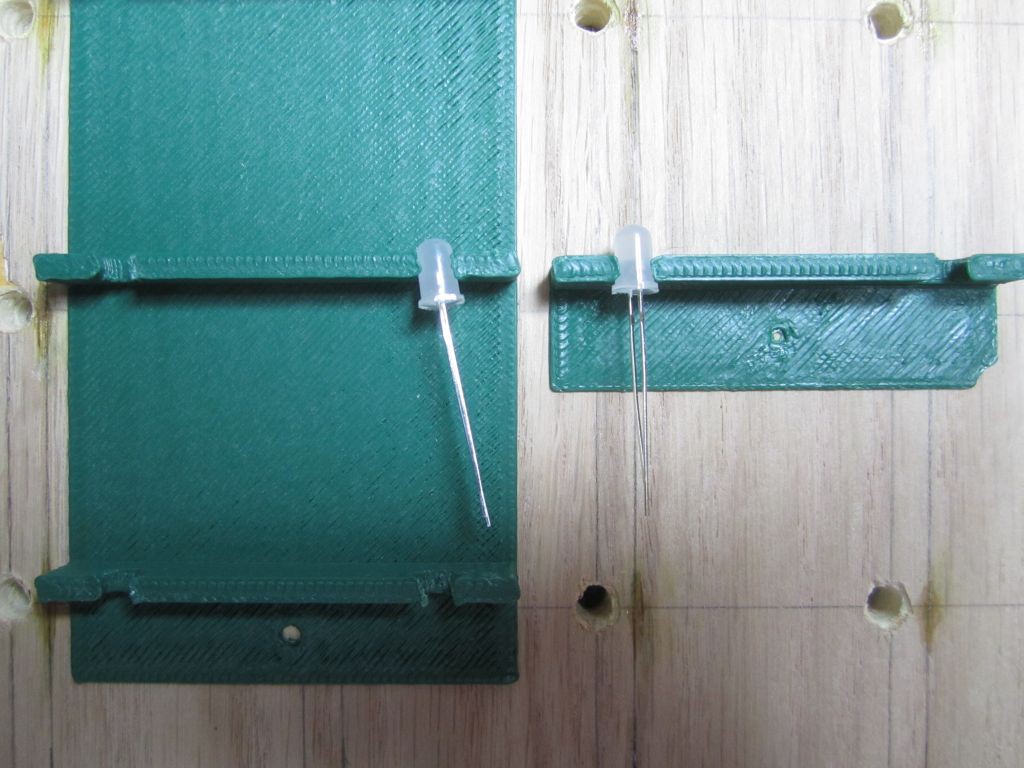
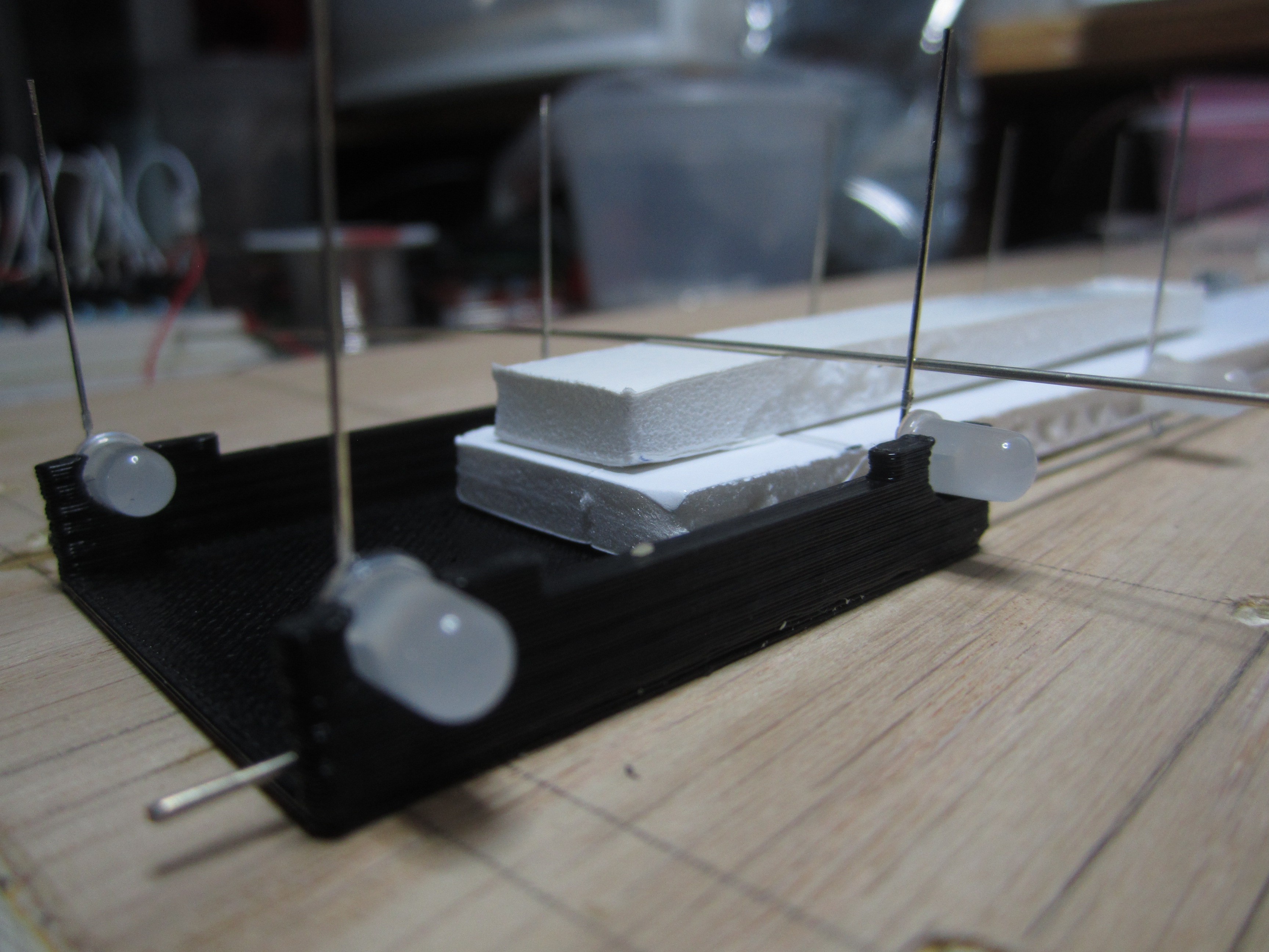
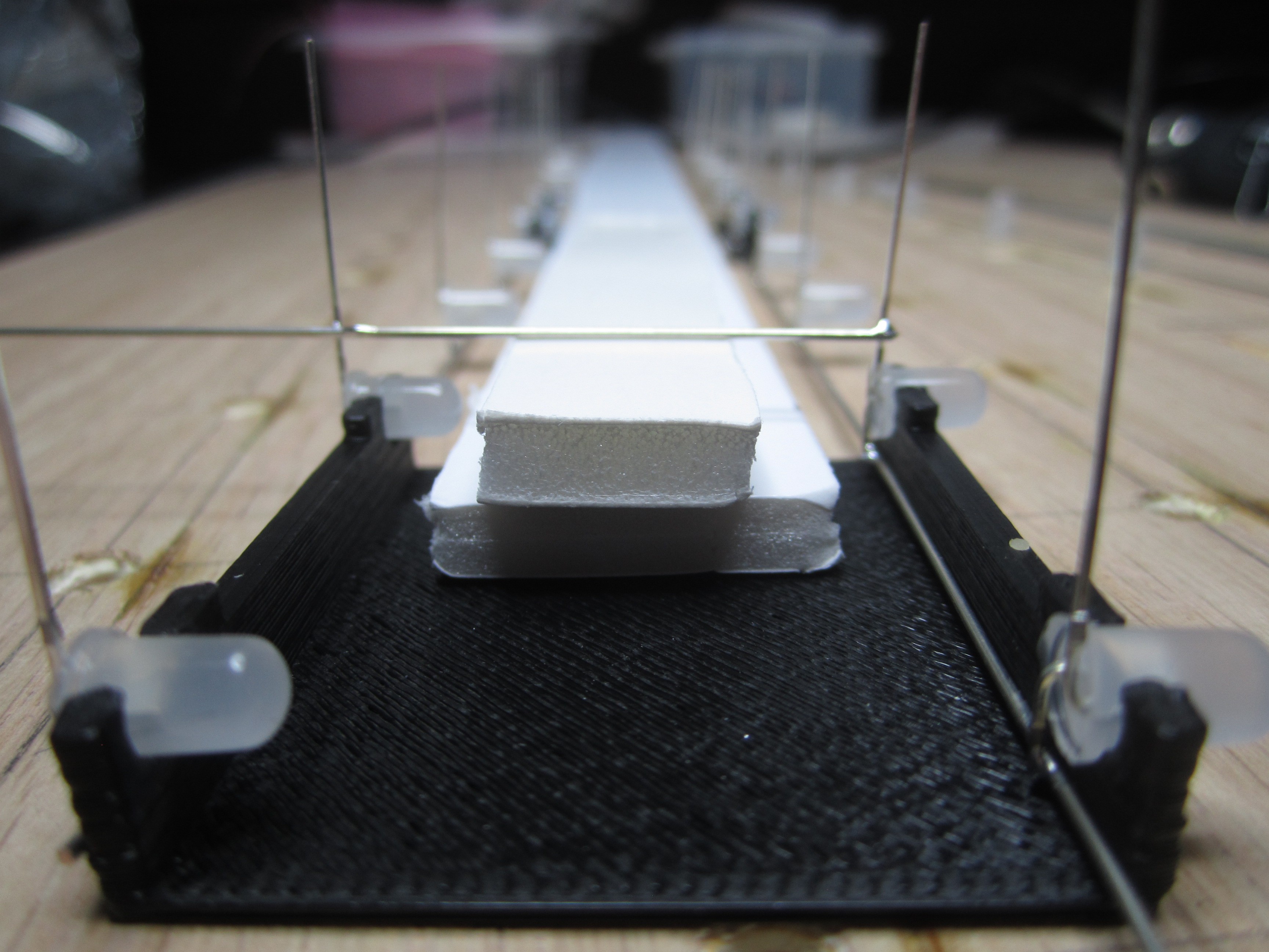
My desire to spread the LEDs beyond the length of the LED leads added a LOT of complexity to the cube construction. More soldering, having to deal with alignment of the extra wires. Larger cube also meant more fragile cube. The result is an impressive 11"x11"x11" cube. However, it took many more hours to build compared to the usual led cube.
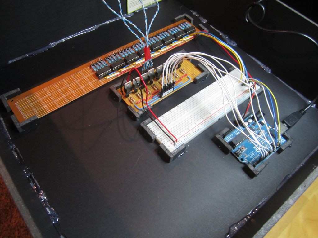
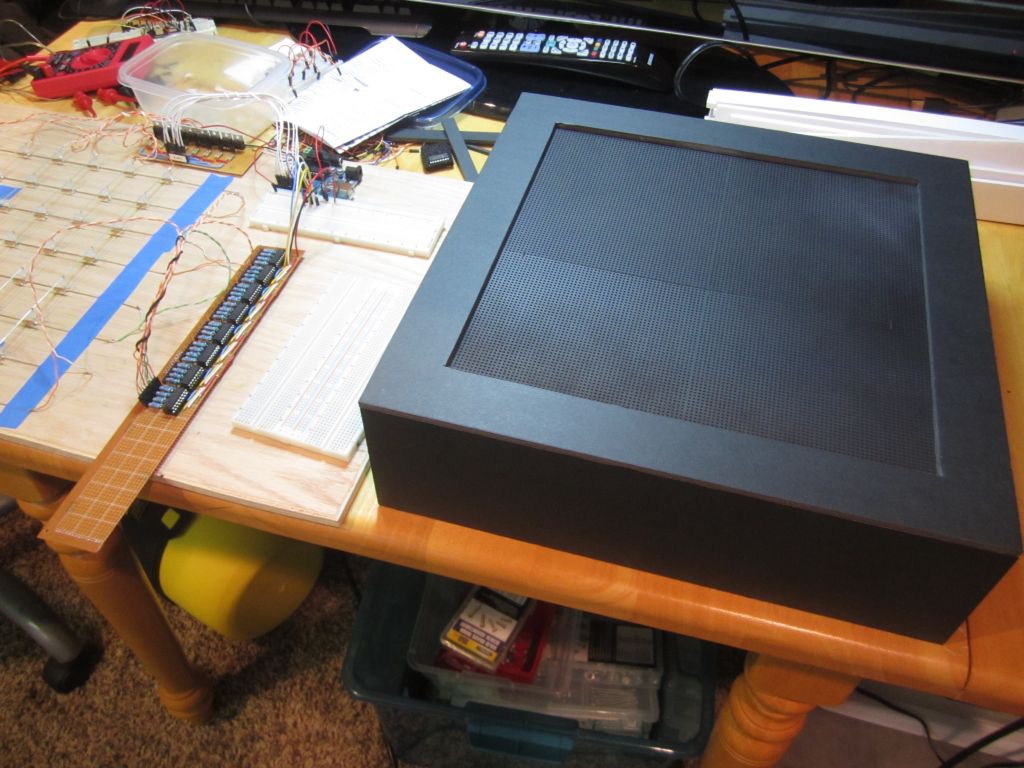
I made a mistake in wiring the ground of the shift register to the AREF pin of the Arduino instead of GND. This resulted a lot of unnecessary circuit, which I was later able to eliminate. The final circuit uses a 2N2222A NPN-Transistor and a FQP27P06 P-Channel MOSFET for each layer, and no extra transistors for the shift registers.
CODE:
Various versions of the code is on github


 Petri Varsa
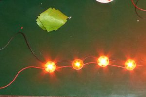
 Joseph Eoff
 davedarko
Is it possible to have more detailed schematics? The one already provided is incomplete