 Sam Barrett
Designing a 3D printed part for structural use is currently done by guesstimation, as there are no accurate models for the material strength. This leads to overengineering at best, or part failure at worst. So, lets fix that! I'll cut straight to the juicy bit: this project showed some pretty promising results in predicting the mechanical strength of 3D printed parts.

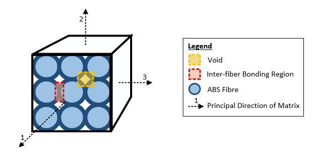
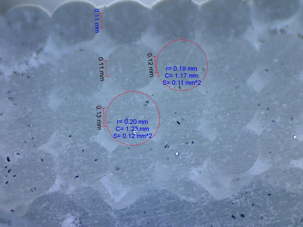
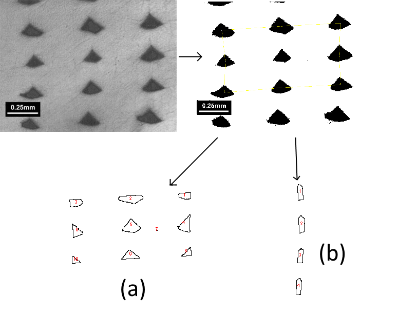
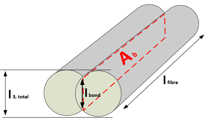
As I'm sure everyone on Hackaday knows, FDM (Fused Deposition Modeling) 3D printing produces components by progressively extruding layers of plastic fibre.
These extrusions only bond to each other partially; voids form in the resulting material which compromise the material strength. Due to these voids, the mechanical strength cannot be simply modelled isotropically (as per engineering materials such as steel, aluminium, etc).
The project is detailed in the four project logs, which should be read in the order below:
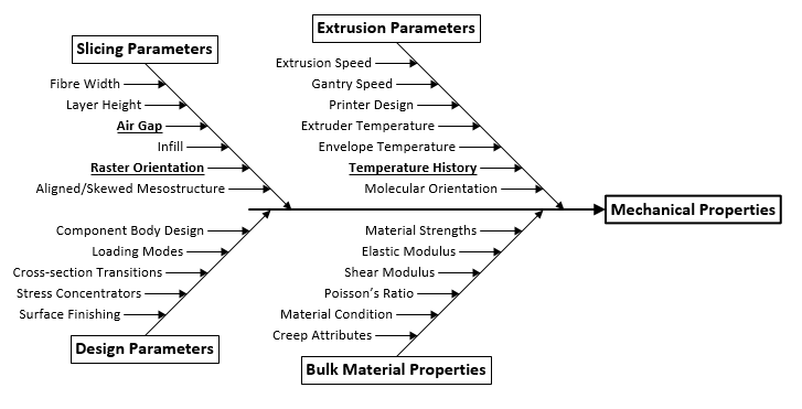
- Influential factors on material strength
- Modelling the material strength
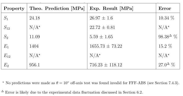
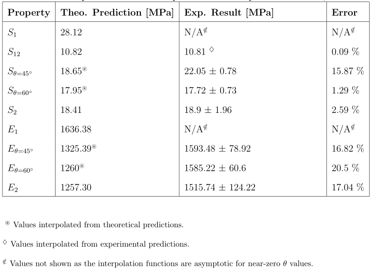
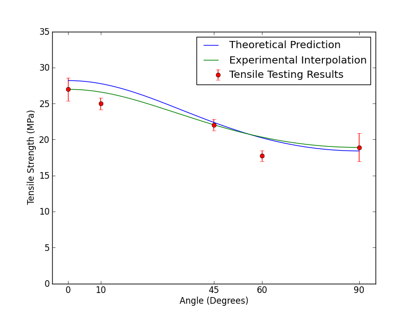
- Testing the developed model
- Future research and contributions
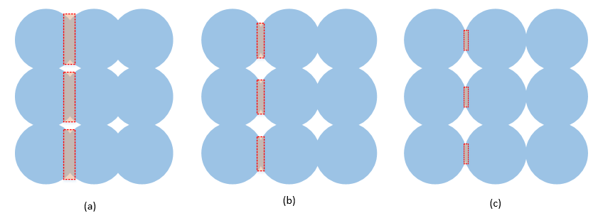
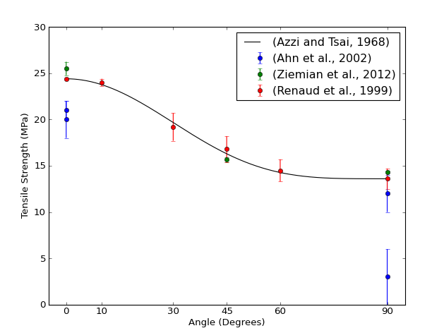
The errors between the prediction and experiment were actually quite small, given that strength prediction of the FDM material has never been done before! This is promising for future work into characterising the properties of FDM material - or perhaps it's simply useful on it's own. Based on the research conducted here, stronger prints can be made by having a more negative air-gap, as interfibre bonding increases.
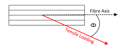
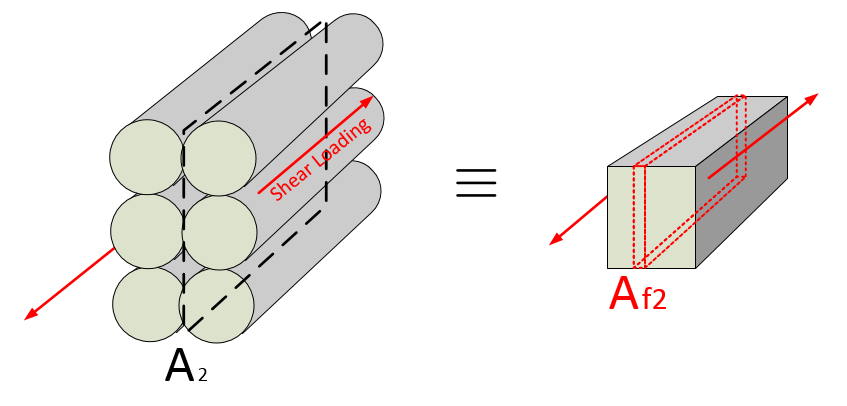
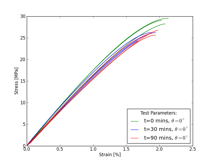
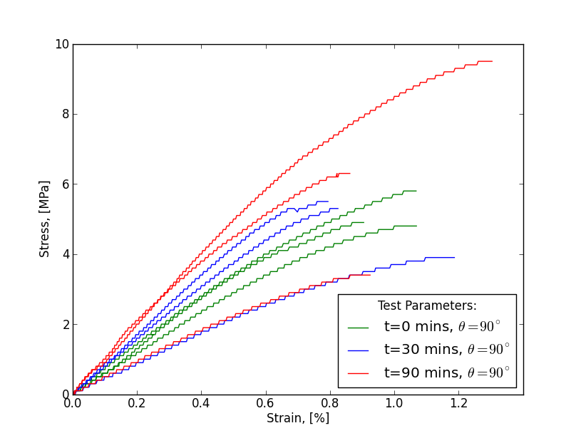
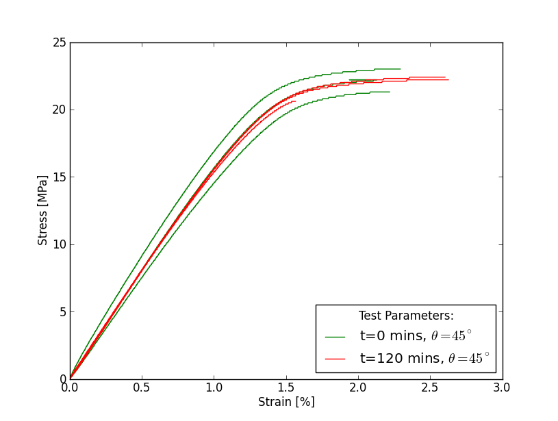
We can also make rough predictions about the strengths of the printed material - it seems reasonable to assume about 25 MPa tensile strength, 10 MPa intralaminar shear strength and 15 MPa transverse tensile strength for ABS under the same conditions - though definitely conduct your own testing before using these values.
If you are interested in this project, I highly recommend reading the full report in the Hackaday files section. Mechanical designers of 3D printed parts may also benefit from the knowledge summary in the report.
This project would not have been possible without prior contributions from others, especially the brilliant minds of academics Ahn, Barbero, Bellehumeur, Li, Sun, Gu, Rodriguez, Renaud, Thomas, Ziemian, Azzi and Tsai. See the research notebook report file for a full reference list.
Note: This project is released as copyleft open source under the GNU General Public License v3. This project was completed as an independent research project as part of an engineering degree.
I release the project, which I alone own full copyright of, as open source for the purposes of entering the Hackaday 'Citizen Science' competition.

 81302
81302
 Yusuke Tanaka
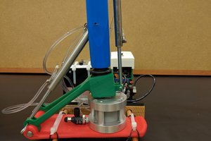
 Aractapod
 Josh Starnes