 Madaeon
Project video:
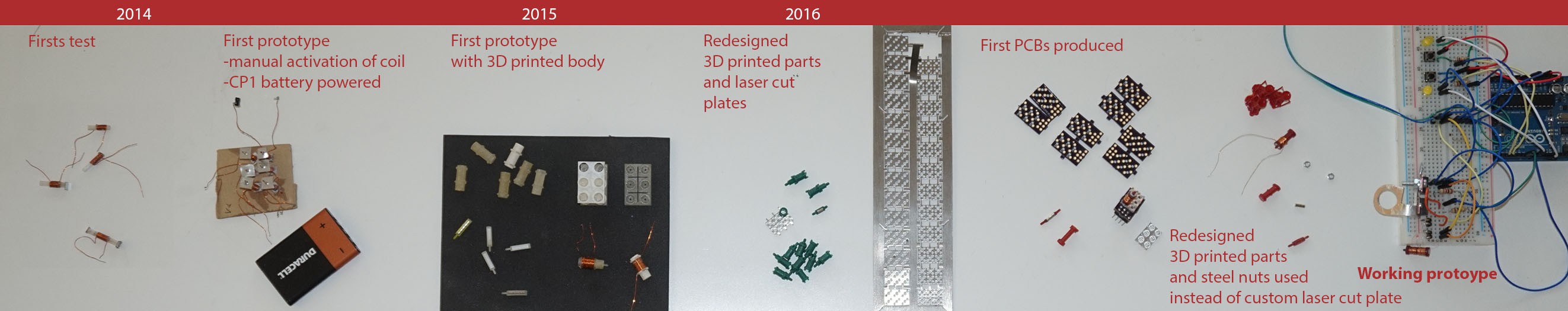
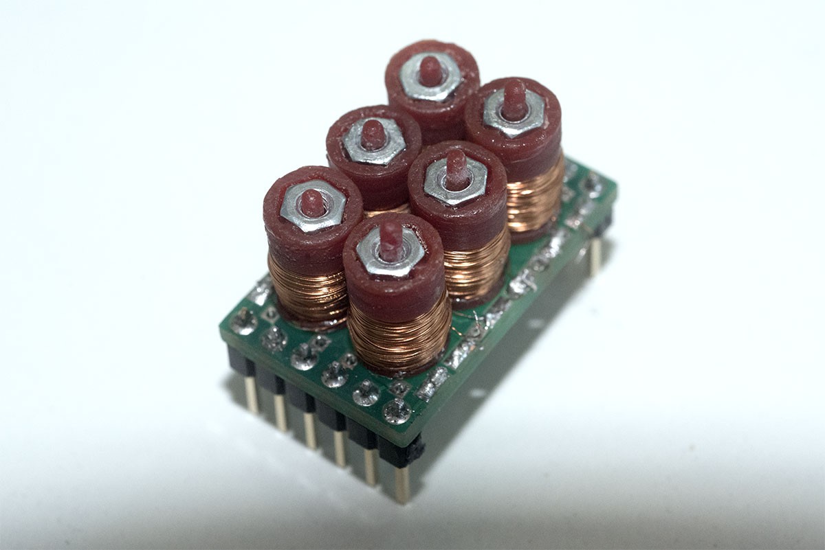
This image shows the development of the project, from the beginning to the current status of development.
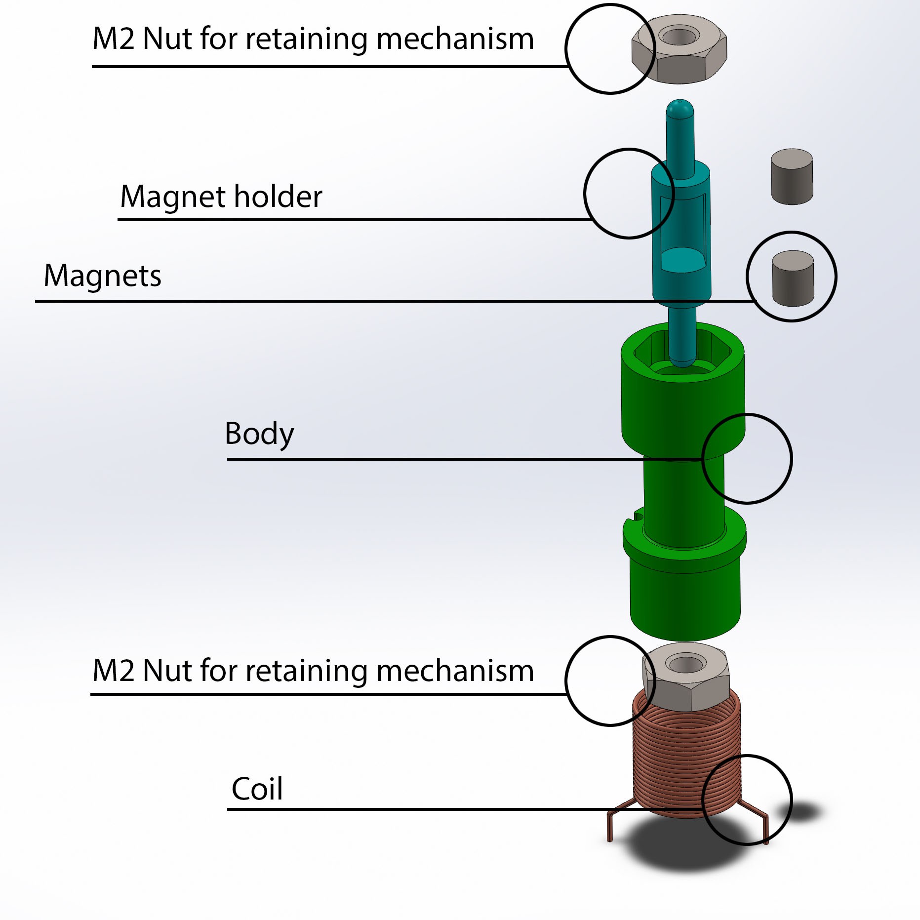
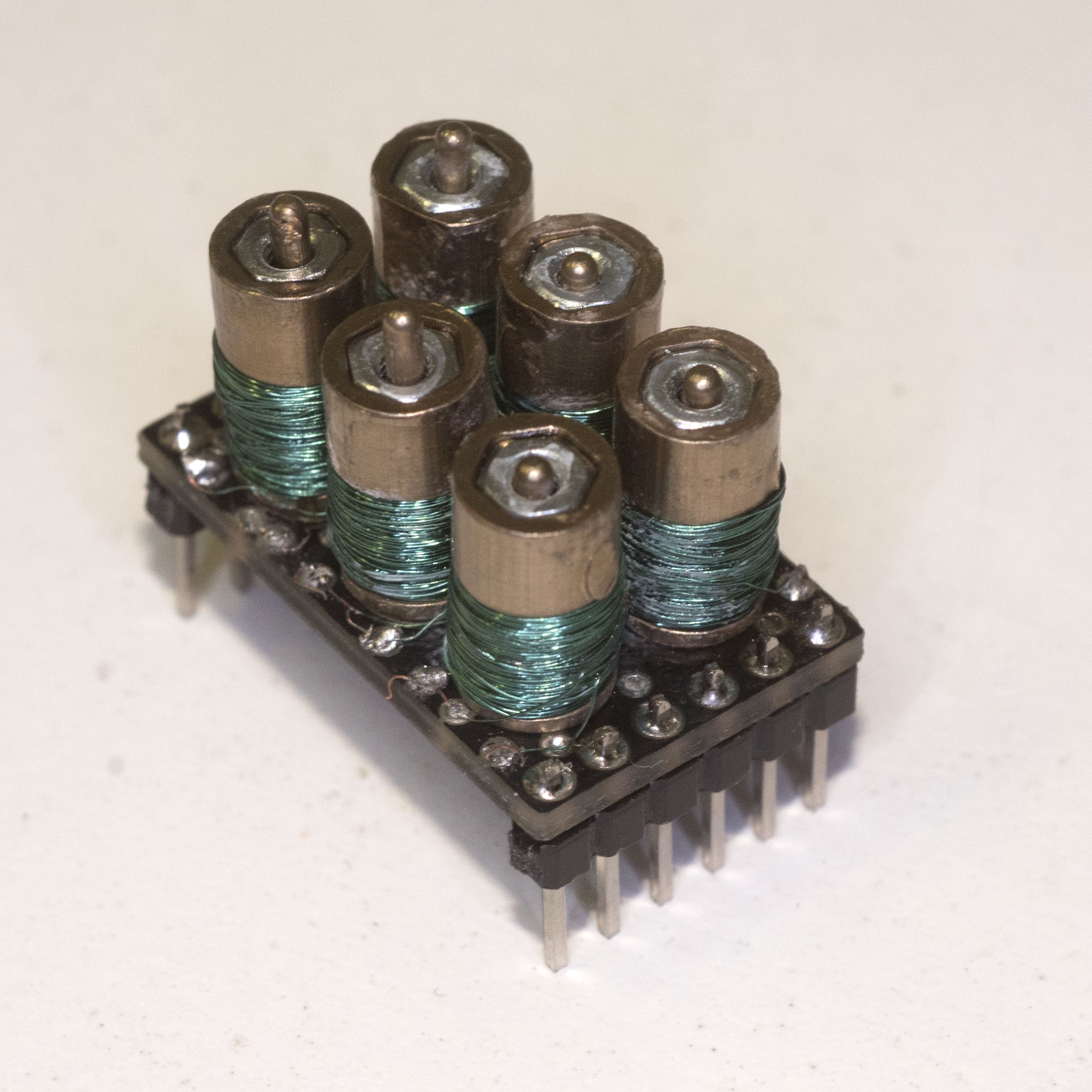
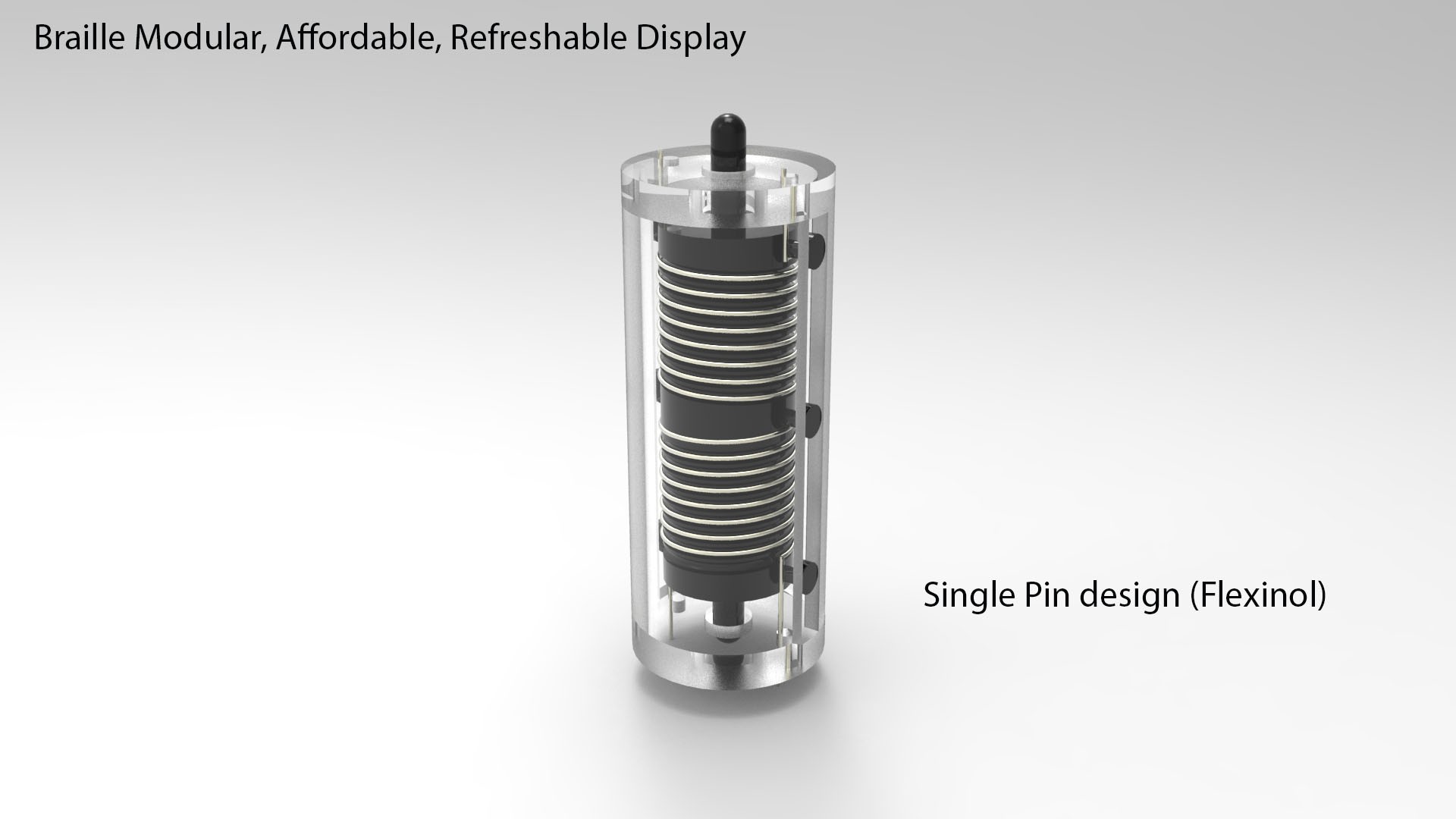
The main idea behind the project is quite simple: For each pin, one coil can move move some very small magnets from one end of a cylindrical body; at each end, two small pieces of ferromagnetic material will hold the pin in position. With this design, power is not needed to keep the state of the pins.
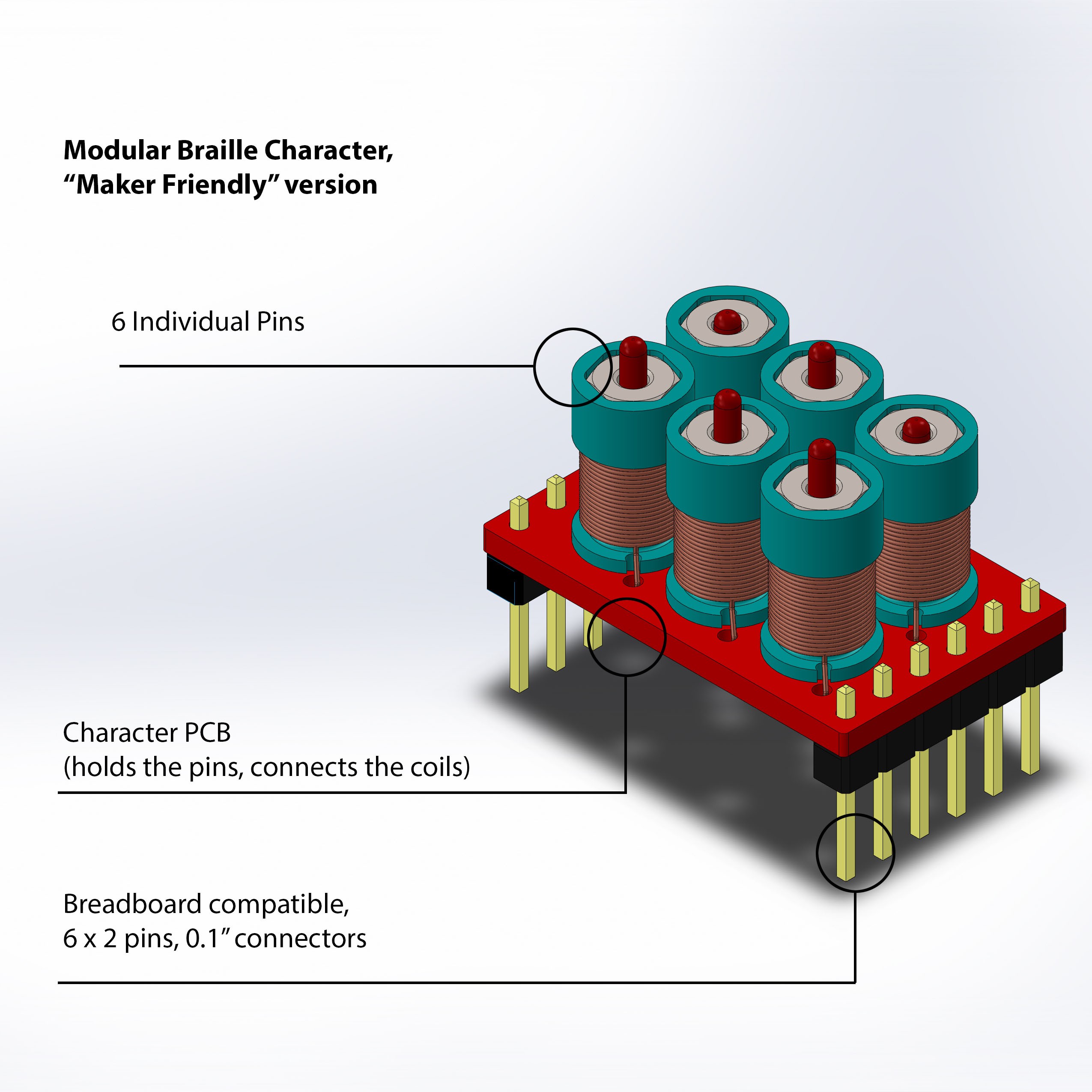
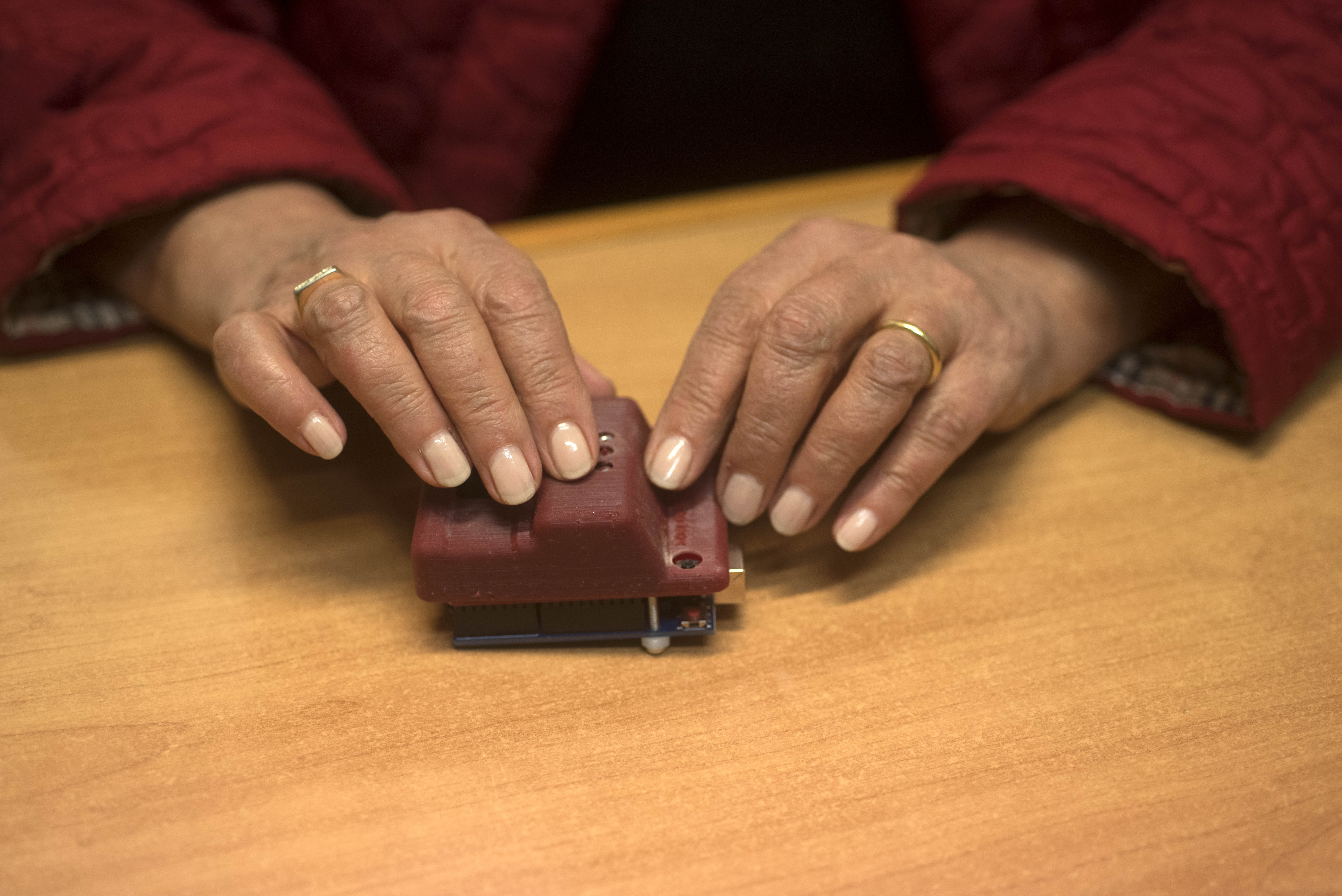
I have successfully tested the pin mechanism, and built some character modules; of course the project is still work in progress and the final size and performances can be greatly optimized.
Now the development has been organized in phases.
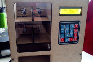
- In the first one, a Maker friendly, breadboard compatible Braille character will be developed. An Arduino demo shield will be developed to test the system and showcase the project.
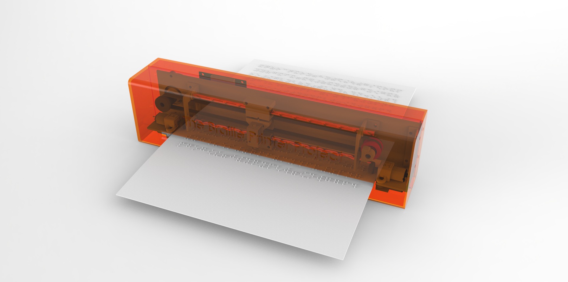
- When the character system will be refined enough, a “LinePCB” will be designed, and will hold 8-10 characters, with a modular approach. A “PagePCB” will then be designed, and will hold 6-8 lines.
- Finally, an entire Braille refreshable screen will be developed, and it may be used for a standalone device like a Braille Tablet, or incorporated into an existing device.
How does it work?
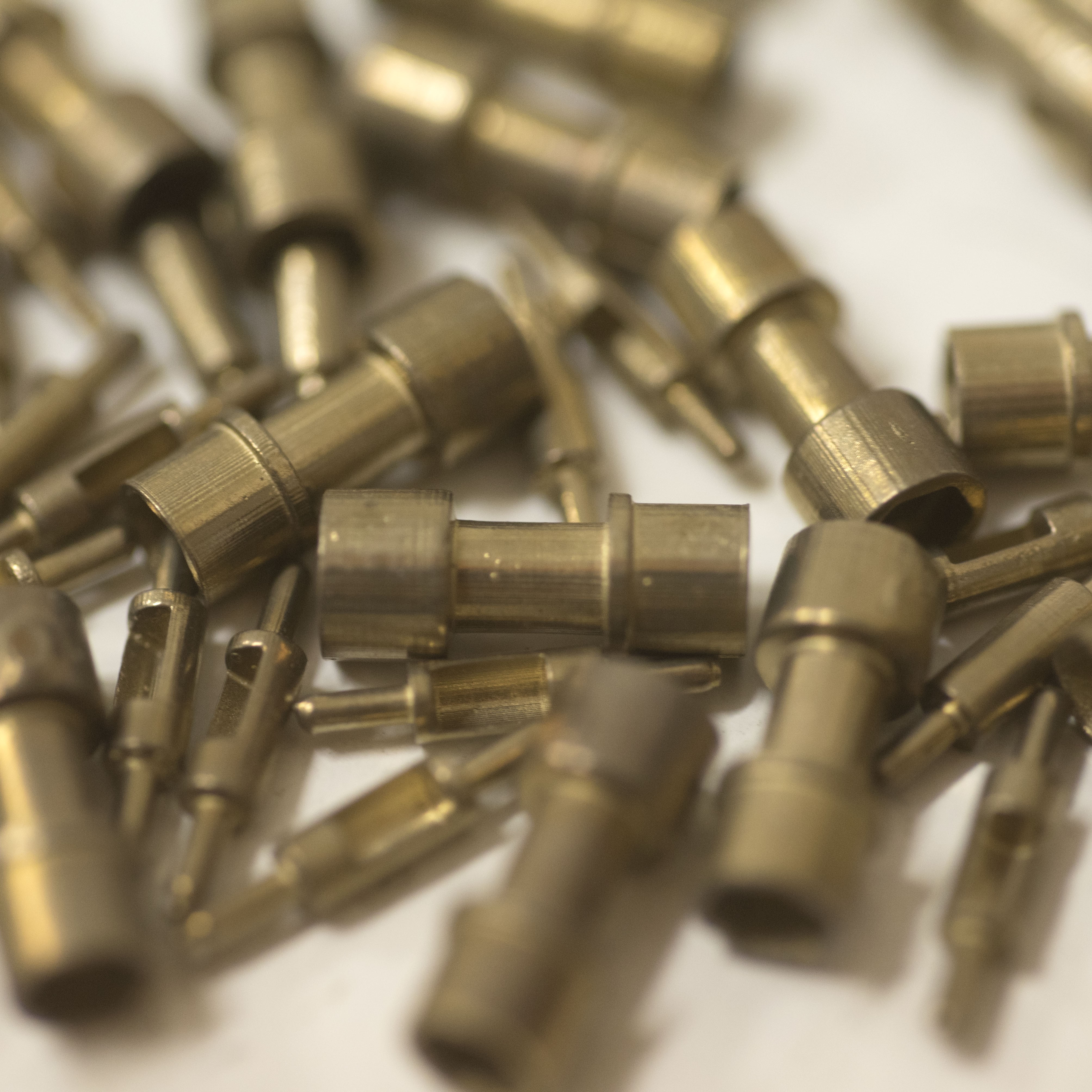
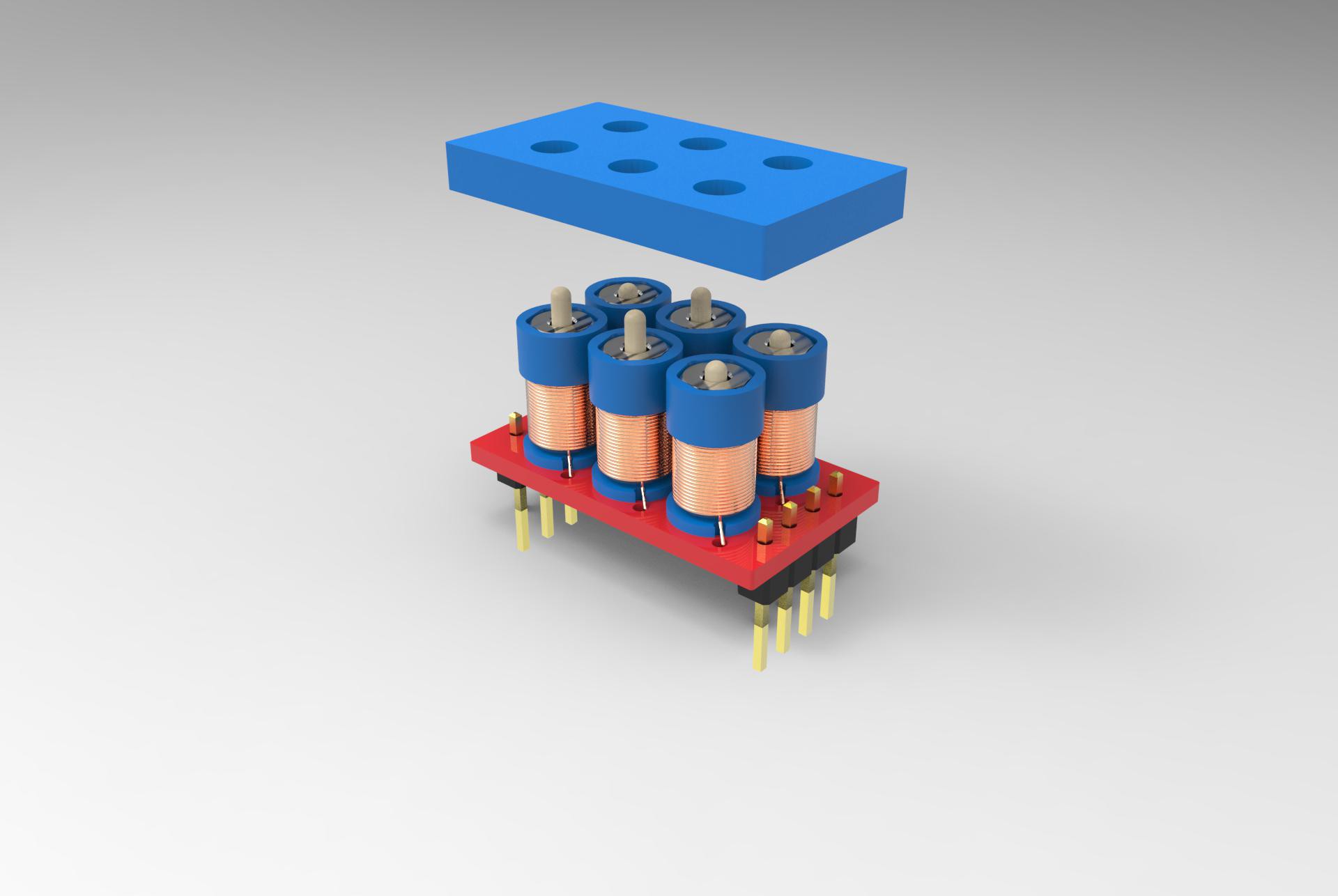
With the current design, each "dot" on a character module is made up of 2 3D printed parts (Body and Magnet holder), 2 M2 nuts, 2 magnets, and 0.1mm enameled wire. A controlling PCB also hold the bodies. This design uses a really low parts count, and efforts have been put to use parts already available, such as the M2 steel nut; this design allows for a very low cost per character.
A (not definitive) cost analysis
The cost for a single pin , for a production in the order of hundreds, is estimated around or less then 0.85€. It includes nuts, 2 injection molded parts (magnet holder and body), magnets, and coil.
The cost for a single character is thus in the order of 5/6€ per character, with a small/medium sized production.
The cost for an entire line of 10 characters is around 120€, including 60€ of characters and 60€ of pcb, most of it due to the TB6612 currently used which are quite expensive.
An hypothetical device with 8 lines, a controlling board, sensors, battery and enclosure should have a total cost of less than 1000€ for a medium/small production, allowing a final retail price of probably 2000€... which is quite not bad compared to the commercial products available today!
 This is a short list of their suggestions / requirements:
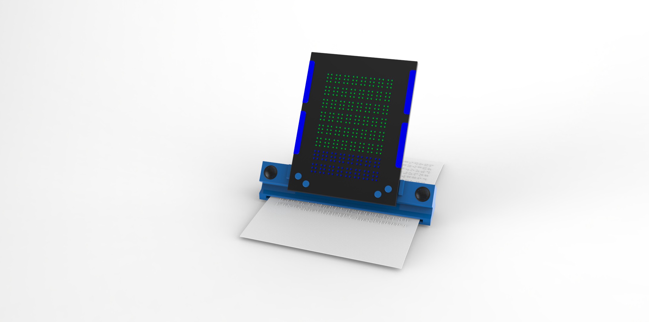


 zapwizard
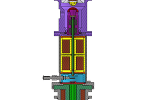
 Vini's Lab
 Gabriel D'Espindula
can you send the circuit diagram of braille project, what you have used in it and also with which code you have run it?