Close
0%
0%

Garage Door Opener

An ESP8266-based garage door opening device

Similar projects worth following
The garage door at my house doesn't have a switch in the garage, so you need the fob. I hate carrying my fob.

So, I could just wire up a simple doorbell switch to the garage door controller, but where is the fun in that?

I plan to build a ESP8266 device, that talks to my home assistant machine via MQTT.

Part of this project is to investigate security of IoT devices. This switch will allow my garage door to open, potentially giving people access to it - it needs to be as secure as possible. I want to see what is involved in doing that.

I also want to investigate serving a usable, well designed single page web app for configuration. It is very common for embedded devices (like routers) to use a web page for configuration, but they are generally terrible. I want to see whether it's possible to make a good one.

As described, the system needs to be secure, so the goals are:

  1. During normal operation, no network ports on the device should be open
  2. The device should connect to an MQTT broker using TLS encryption
  3. The device needs to verify the host that it is connecting to is who it says it is
  4. Configuration will be done via a captivate portal that will only be created when physical buttons on the device are pressed.

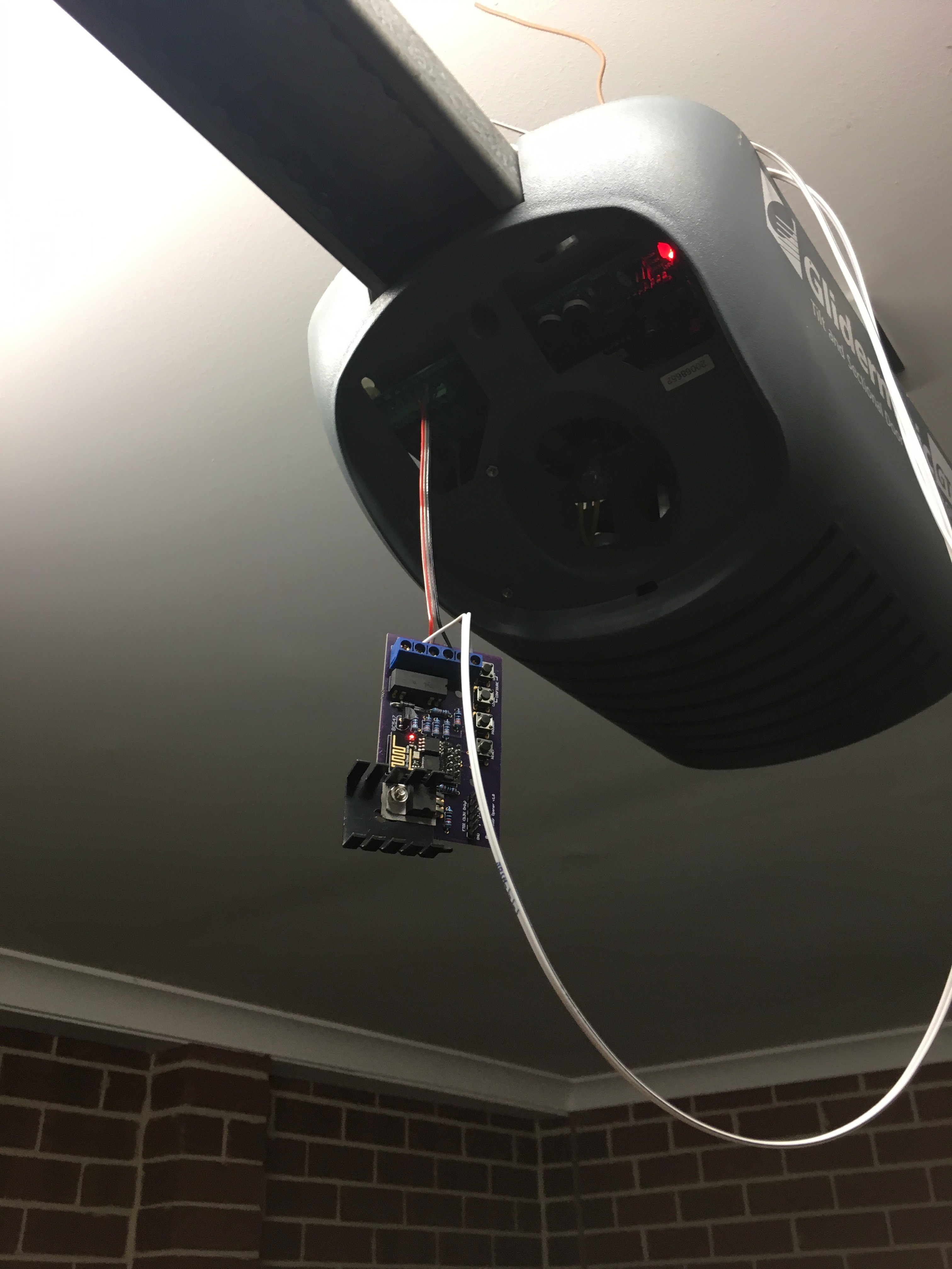
I'm planning on integrating the device with a locally-running copy of Home Assistant. Ideally I can get the homekit integration working, so I can ask Siri to open it via my Apple Watch.

I want to the build to look like a finished piece, so I'm going to design a custom PCB for it.

I also want to investigate building a user-friendly, usable, well designed single-page web app for the captivate portal configuration screen. The design goals for this part are:

  1. Due to the limited resources on the device, the HTML, CSS and JavaScript should be as small as possible. This means no libraries, heavy minification tricks and pre-gzipping of the web page.
  2. Useability is the highest priority, followed by size, followed by speed. Browsers run on powerful computers, so they can do a bit more work if it means shaving size off the deliverable.
  3. Ideally it should be bundled as part of the firmware, and not as a binary blob uploaded to the ESP8266 filesystem.
  4. It should require no external network assets - everything delivered must live on the ESP8266.

garage-door-opener.sch

Schematic v1.0 - Note: There is an error in this version - the TX/RX pins on the FTDI connector are swapped (From what seems to be the standard pinout)

sch - 225.95 kB - 08/01/2016 at 02:26

Download

garage-door-opener.brd

PCB v1.0 - Note: There is an error in this board - the TX/RX pins on the FTDI connector are swapped (From what seems to be the standard pinout)

brd - 94.33 kB - 08/01/2016 at 02:26

Download

  • 1 × ESP8266-01 The brains of the operation
  • 1 × LM317T Variable Voltage Regulator The garage door controller supplies 12V, we need 3.3V
  • 1 × 200R resistor For the regulator feedback circuit
  • 1 × 120R resistor For the regulator feedback circuit
  • 1 × 330R resistor A pull up resistor for the RX line

View all 14 components

  • Modifying the ESP8266 Over-the-Air update code

    Myles Eftos03/30/2017 at 08:59 1 comment

    Now that I have the proof of concept code running, it's time to modify the built in Arduino core library that handles OTA updates.

    The existing OTA library takes a binary object and an optional MD5 hash (to verify the upload), stores it in flash memory, then swaps the old binary out of the new binary and reboots the device.

    To do verification via digital signatures, we need three additional pieces of information: the developers certificate (used to decrypt the hash), the encrypted hash, and the Certificate Authority certificate used to verify the developers signature.

    The CA needs to be compiled in to the source code - there is little point sending that along with our payload.

    The developer certificate and encrypted hash on the other hand, need to be supplied with the binary . One option is to upload the three files separately, but this would require extensive reworking of the updater API, and of the OTA libraries.

    A better option would be to somehow bundle all three files in one package, which is the path I am looking to go down.

    So, the first thing to do is work out what the file format looks like.

    The binary blob is of an arbitrary size, and starts with the magic byte: 0xE9, which I assume is an instruction that is required to start the boot process.

    Our certificate is also an arbitrary size. The signature will be fixed size, but dependent on the algorithm we use. Clearly we need some way of instructing the updater code where the boundaries for each file are.

    We could pack them at the beginning, and set the byte before the file with the expected length - ie if our signature was four bytes, and certificate was 6 bytes it might look like this:

    [ 4 | s | s | s | s | 6 | c | c | c | c | c | c | ... ]

    but that would mean we'd have to move the data around, as the bootloader would be looking for the magic number in the position 0. I've decided to do it the other way around - I'm going to use the last two bits to signify the lengths, and then count backwards. ie:

    [ ... | c | c | c | c | c | c | s | s | s | s | 6 | 4 ]

    I wrote a quick little c program that packages everything up.

    #include <stdio.h>
    #include <stdlib.h>
    unsigned char *bundle;
    uint32_t size;
    uint32_t certificate_size;
    uint32_t signature_size;
    int main() {
      FILE *f1 = fopen("WebUpdater.ino.bin", "rb");
      if(f1) {
        fseek(f1, 0, SEEK_END);
        size = ftell(f1);
        rewind(f1);
        printf("Binary file size: %i\n", size);
      } else {
        printf("Unable to open WebUpdater.ino.bin\n");
        return -1;
      }
      FILE *f2 = fopen("developer.crt.der", "rb");
      if(f2) {
        fseek(f2, 0, SEEK_END);
        certificate_size = ftell(f2);
        rewind(f2);
        printf("Certificate size: %i\n", certificate_size);
      } else {
        printf("Unable to open developer.crt.der\n");
        return -1;
      }
      FILE *f3 = fopen("WebUpdater.ino.sig", "rb");
      if(f3) {
        fseek(f3, 0, SEEK_END);
        signature_size = ftell(f3);
        rewind(f3);
        printf("Signature size: %i\n", signature_size);
      } else {
        printf("Unable to open WebUpdater.ino.sig\n");
        return -1;
      }
      printf("Signature size: 0x%x\n", signature_size);
      uint32_t bundle_size = size + certificate_size + signature_size + (2 * sizeof(uint32_t));
      bundle = (unsigned char *)malloc(bundle_size);
      for(int i = 0; i < bundle_size; i++) {
        bundle[i] = 0;
      }
      fread(bundle, size, 1, f1);
      fread(bundle + size, certificate_size, 1, f2);
      fread(bundle + size + certificate_size, signature_size, 1, f3);
      bundle[bundle_size - 4] = signature_size & 0xFF;
      bundle[bundle_size - 3] = (signature_size >> 8) & 0xFF;
      bundle[bundle_size - 2] = (signature_size >> 16) & 0xFF;
      bundle[bundle_size - 1] = (signature_size >> 24) & 0xFF;
      bundle[bundle_size - 8] = certificate_size & 0xFF;
      bundle[bundle_size - 7] = (certificate_size >> 8) & 0xFF;
      bundle[bundle_size - 6] = (certificate_size >> 16) & 0xFF;
      bundle[bundle_size - 5] = (certificate_size >> 24) & 0xFF;
      FILE *f4 = fopen("Bundle.bin", "wb");
      if(f4) {
        fwrite(bundle, bundle_size, 1, f4);
        printf("Bundle size: %i\n", bundle_size);
      } else {
        printf("Unable to save Bundle.bin"...
    Read more »

  • Signing a binary using axTLS

    Myles Eftos03/12/2017 at 04:21 0 comments

    Comparing the SHA256 of a file after it has been uploaded allows us to check that it hasn't changed. This doesn't tell us if the file has been tampered with though - it would be easy enough for a someone to change the binary, and then change the hash so it matches.

    To check the file was created by the person who said it was created by, we need to verify a cryptographic signature. The steps are fairly simple:

    1. We upload the new binary, our public key and the signature file.
    2. We check that the public key has been signed by a trusted certificate authority - if this fails, the CA can't vouch for the person signing it, so we shouldn't trust it.
    3. We decrypt the signature file using the public key. This is the original SHA256 hash of the binary. If we can't decrypt it, we can't compare the hashes
    4. We SHA256 the binary ourselves
    5. We compare the hash we computed with the file that was uploaded. If the two hashes match, then the binary hasn't been tampered with, and we can trust it.

    I took the previous POC code, and extended it to do just that.

    I've covered generating a certificate authority before, as well as generating a certificate. The last bit to do is to sign out binary. Again, using OpenSSL:

    openssl dgst -sha256 -sign cert/developer.key.pem -out data/sig256 data/data.txt

  • Signing Over-the-Air updates

    Myles Eftos03/05/2017 at 09:59 0 comments

    The garage door opener has been running pretty well for the past couple of months, but I still have some work to do. I haven't built out the configuration interface yet, and it turns out that if Home Assistant restarts, it forgets the last open state, so with out opening and closing the door again, I don't know the state of the door.

    This means I need to update the firmware.

    The ESP8266 has facilities to do Over-the-Air (OTA) updates, however it doesn't verify that the uploaded binary has been compiled by the person the device thinks it has. The easiest way to do this is to create a digest hash of the file and sign it. Then the device can verify the hash and check the signature matches.

    There is an issue to implement this on the ESP8266 Github page, so I thought I would have a look at implementing something.

    The first step is to be able to compare a hash. I decided to use the AxTLS library, as it has already been used for the SSL encryption on the device. After a google search, I found this page that outlines has to verify a SHA1 + RSA signature.

    I simply pulled the sha1.c file (renamed it sha1.cpp), and created a sha1.h file that defines the functions in the cpp file. Next I created a test file, and hashed it using openssl:

    openssl dgst -sha1 -binary -out hash data.txt

    I then uploaded the files to the ESP8266 SPIFFS filesystem, and wrote some quick POC code.

    The computed hash matches the supplied hash. Step 1 complete!

    The next step will be to generate a signed digest, and decrypt that.

  • Yeah. So it works

    Myles Eftos12/04/2016 at 19:56 0 comments

  • Hardware test

    Myles Eftos11/28/2016 at 10:36 0 comments

    Even though I still have to complete the captivate portal, and over-the-air updates, It seemed like a good time to wire the controller in and see how it all works off the bench.

    It's a good thing I did, as I discovered a few issues with the board.

    Excuse the wiring, it's just temporary...

    Originally, I had two switches: one of when the door was completely open, and one for completely closed. Based on the last state, I could guess whether the door was opening or closing. I must admit, I realised long after I ordered and built the board that I really only needed one switch that indicated the closed position. Good thing really, because the device got completely confused after I installed it.

    Back story

    Because of the limited number of IO pins on the ESP8266-01, I had to pull some tricks to give me two switches and a relay (I can't take credit, this is an amalgam of a bunch of stuff I found Googling).

    There are 4 GPIOs, two of which are shared with the TX and RX pins on the serial port. To make things even more interesting, GPIO0 needs to be held high on boot, otherwise the device goes in to programming mode.

    This means GPIO0 is no good as a switch interface - if there was a power outage and the switch attached to GPIO0 was closed as it rebooted, the device would be stuck in program mode.

    Conversely, when the device boots up, there is a bit of chatter on TX, so putting the relay on that would be risky - a reboot could cause the door to trigger, and open it when no one was home.

    Wiring the relay to GPIO0 and GPIO2 is quite easy, pull them high with pull-up resistors, then switch them to outputs during the setup phase. Setting them both low at the same time sets the relay up. Pulling GPIO2 up, drives the base of a transistor and energises the relay. While the output of the chip could drive the relay directly, I'm actually using a 12v relay that is driven from the convenient 12V output from the garage door controller, so the transistor is required to switch the higher voltage from the lower 3.3V coming out of the regulator.

    The "closed" switch is wired to the RX pin, and the "open" switch is wired to the TX pin. This means that the Serial Port is disabled, which can make debugging difficult, so as I work, I usually disable the switches.

    This all worked fine on my bench, but as soon as I installed it the close switch wouldn't register properly, and I couldn't work out for the life of me why. I suspect the internal state machine wasn't transitioning properly, possibly because of contact bounce, but it turns out it didn't matter - I also found what I would call a show stopper: I discovered that if the TX pin was held high (ie the device booted when the door was open) it would never start.

    Not ideal.

    In a quick refactor of the code, I disabled the state machine, replacing it with a simpler open/close state - if the "closed" switch is closed, the device reports closed, if it's open, it reports open. Keep it Simple. Who knew, right? Another nice side effect is I can use Serial.println for debugging again. Bonus.

    So that brings the mistake count for that board up to four - thankfully all workaroundable (totally a word)fairly easily:

    1. "Open" switch not needed
    2. TX and RX pins on the FTDI connector are transposed (fixed by modifying my FTDI cable, which I'm sure will come back to bite me at some point)
    3. Originally, the GND for both switches shared a screw terminal, although now I can get rid of the open switch, I can keep the board to five screw terminals.
    4. No room for the heatsink
    5. (Improvement) Add a jumper to switch between using the 5V off the FTDI cable and an external supply - I was using a fly leads soldered to the bottom of the board while testing.

    As a PCB board designer, I'm an excellent software engineer.

  • Storing the configuration II

    Myles Eftos11/27/2016 at 22:37 0 comments

    I wrote about my "generic" config class in a previous build log, and alluded to how I wasn't really sure it was the best plan of attack.

    It wasn't.

    All of the casting was painful, the setup was annoying and unnecessary (From both a memory and CPU time POV) - there was little (if any) advantage in using it.

    In the end, I wrote a concrete class with mutators for each attribute. This meant each attribute is already the correct type, so there was no annoying casting, and I could control and optimise the serialisation and deserialisation.

    You can see the class on Github.

    The mutators are pretty straight forward, as is the serialisation:

    The boolean values (as well as encryption mode and mqtt Auth mode) are compacted using bit-masks, effectively fitting five config items into one byte. Next, I store single integer and double integer values (I use doubles for port numbers), and finally strings.

    The strings are encoded by putting their length in the first byte, effectively limiting string length to 255 characters, which is fine - DNS names are limited to this, and that is the biggest thing the config will store. It also makes it possible to avoid overruns, as we have an effective upper limit, so if we go past that index, we know something is broken.

  • TFW you realise you need a heatsink

    Myles Eftos11/22/2016 at 10:48 0 comments

    Up until now I've been testing the door opener using a pigtail off the 5V line on the FTDI cable - the board has a LM317T regulator setup to output the 3.3V that the ESP8266 requires. The installation point for this board is a 12V output from the garage door controller. Those of you with a bit more experience with voltage regulators would realise where this is going... I plugged the board in to a 12V supply and noticed that the regulator was getting really hot.

    On my lunch break today, I made my way to Jaycar to grab a heatsink. I was thinking about the little clip on ones, which I looked up on the website while I was on the tram, and I came across "thermal resistance" in the specs.

    I had no idea what this was, but I knew that it was probably an interesting specification to look up. After googling it, I discovered it is a measure of how many degrees the heatsink will heat up per watt it is dissipating. Some more googling and I found this page around heatsinking the LM317T, which had all the magic formulas that I needed.

    So, the power dissipation is:

    P = (Vin - Vout) * I

    I had two parts of that equation: Vin = 12V input, and Vout = 3.3V, so I needed to work out the power draw of the ESP8266.

    More Googling...

    I found these (anecdotal) results, which sounded reasonable. So taking the peak current of 320mA, the power is:

    P = (12 - 3.3) * 0.32
    P = 2.784W

    Apparently, the maximum Thermal Resistance the regulator can tolerate is calculated by:

    T(rmax) = (60 - roomtemp) / P

    So, let's make roomtemp = 20 (Yes, I'm in Australia, but I'm also in Melbourne, so that is a good average), giving us:

    T(rmax) = (60 - 20) / 2.784
    T(rmax) = 14.37 C/W

    The little clip on heatsinks have a thermal resistance of 30 C/W, which is double what we need.

    Boo.

    By this stage I had arrived at the store, so went to the heatsink section to see what they had. They had this guy, which has a thermal resistance of 12 C/W. Perfect! It was quite large though, and I knew they board was tight, so I had to be a little creative in fitting it.

    Don't judge me.

    I'm a little annoyed that it doesn't sit on the board properly, but I couldn't stand it up, as there was limited room above the board, so it was the best I could do without redesigning an new board.

    It'll do.

  • Doubling capacity.

    Myles Eftos11/21/2016 at 21:29 0 comments

    So, it turns out the ESP8266-01 (at least the one I have) supports 1MB of storage. I had been butting up against the 512kB I thought I had, and it turns out I needn't worry.

    Running this command:

    ESP.getFlashChipSizeByChipId()
    Will tell you what your chip supports.

    This means I can probably incorporate Over-the-air updates, which will be handy. I still need to keep the image under 512kB (OTA needs the space to upload the new image).

    w00t!

  • mDNS: A Teardown.

    Myles Eftos10/17/2016 at 21:14 0 comments

    Trying to get mDNS queries working hasn't quite been as straight forward as I was hoping. I mentioned in a previous log that I found a library, but it was a little overkill for what I need, so I did what any silly software developer does: started rolling my own.

    How am I justifying this? Well, I'm fast running out of space. The GitHub version of the ESP8266 hardware definition I'm using is significantly larger than the distributed version, so I only have about 10k of program storage left - as a result I'm being more weary of how much source code I'm uploading. Since I don't need to respond to mDNS questions (the ESP libs have one built in), I can skip question parsing, and since I'm only interested in name browsing, I can ignore a all bar two classes of responses. And sometimes learning a protocol can be fun. Sometimes.

    My completed library can be found here.


    The first thing I did was work out how mDNS works. It's a pretty clever hack - It reuses standard DNS packets, but rather than ask a specific DNS server to answer a query, mDNS clients just broadcast a UDP packet to anyone who will listen. If another listener can answer the question, it broadcasts the answer. You can see more information about the packet format on the mDNS Wikipedia page.

    Looking at the packet structure, and looking through the code from this mrdunk's library, as well as some packet sniffing using wireshark, I was able to generate questions and parse answers. This was very much proof of concept code that was embedded in my project, and it worked, though it lacked formal testing, and this would definitely be something I would want to reuse in the future.

    ime to break it out in to another library.

    Now, my C++ isn't particularly strong, so this sounded like a good opportunity to learn more about C++ classes. I had a niggling concern around code size, memory usage and speed when it came to using C++ for embedded systems, so I did a bit of research around best practices, and found this article. What I found particularly useful in the article was the explanation of how C++ achieves what is does in terms of the equivalent C code. This clicked in to place what C++ was doing and allowed me to make some better decisions around structuring my library. Though I did get tripped up. A lot

    The basic rules are:

    • Don't use exceptions (you can't on Arduino), so most functions return a status code indicating success or error states.
    • Avoid virtual functions where possible, because you end up with a vtable which takes up memory and requires extra cycles to lookup where the address of the required function
    • Avoid dynamic memory
    • If you need dynamic memory, free it as soon as possible, or make it super long living to avoid fragmentation
    • Don't include unnecessary libraries. I thought I would do the right thing and use std::string which abstracts string handling. This made my library's object file an order of magnitude larger. Reverting back to regular char* string keped everything nice and small, and as I didn't need to do much actual string manipulation, the trade of was totally worth it.

    Testing

    I'm a big believer in automated testing. Especially for something as low level as a library where you rely on certain types of network packets. Automated testing on an Arduino is probably possible, but since I'm not doing anything too Arduino specific, I was able to build a test suite that ran on my laptop. This made the test cycle much quicker as I didn't have to wait for my code to upload. The downside is I need to mock out a few objects, but with some clever code organisation I managed to avoid too many mocks.

    I found Catch which is a header-only, lightweight testing framework for C++. It was pretty easy to setup, and works with TravisCI, so every time I commit a change the tests run automatically.

    Travis was a bit of a pain to setup, as the C++ they run is ancient, so I needed to setup a custom toolchain in travis.yml.

    Once I had everything written and tested, I was able to drop it...

    Read more »

  • An mDNS library

    Myles Eftos09/25/2016 at 22:37 0 comments

    I've mentioned before that I plan on using mDNS to resolve the name of my server. While the ESP8266 Arduino library can broadcast a mDNS name, it doesn't query mDNS when resolving names. I found mrdunk's mdns on Github that implements enough of the mDNS protocol, that I should be able to hack mDNS name queries into the project.

    I spun up a quick proof of concept sketch to see how it all works.

    // This sketch will display mDNS (multicast DNS) data seen on the network.
    
    #include <ESP8266WiFi.h>
    #include "mdns.h"
    
    // When an mDNS packet gets parsed this optional callback gets called once per Query.
    // See mdns.h for definition of mdns::Answer.
    void answerCallback(const mdns::Answer* answer){
      if(strcmp(answer->name_buffer, "mqtt.local") == 0) {
        Serial.print("Name: ");
        Serial.println(answer->name_buffer);
        Serial.print("Answer: ");
        Serial.println(answer->rdata_buffer);
        Serial.print("TTL: ");
        Serial.println(answer->rrttl);    
      }
    }
    
    // Initialise MDns.
    // If you don't want the optional callbacks, just provide a NULL pointer as the callback.
    mdns::MDns my_mdns(NULL, NULL, answerCallback);
    
    void setup() {
      // Open serial communications and wait for port to open:
      Serial.begin(115200);
    
      // setting up Station AP
      WiFi.begin("[ssid]", "[password]");
    
      Serial.print("Connecting to WiFi");
      // Wait for connect to AP
      int tries = 0;
      while (WiFi.status() != WL_CONNECTED) {
        delay(500);
        Serial.print(".");
        tries++;
        if (tries > 30) {
          break;
        }
      }
      Serial.println();
    }
    
    void query(const char *name) {
      mdns::Query q;
      
      int len = strlen(name);
    
      for(int i = 0; i < len; i++) {
        q.qname_buffer[i] = name[i];
      }
      q.qname_buffer[len] = '\0';
        
      q.qtype = 0x01;
      q.qclass = 0x01;
      q.unicast_response = 0;
      q.valid = 0;
    
      my_mdns.Clear();
      my_mdns.AddQuery(q);
      my_mdns.Send();
    }
    
    int send = 0;
    void loop() {
      if(send == 0) {  
        query("mqtt.local");  
        send = 1;
      }
      my_mdns.Check(); 
    }

    The sketch sends a query out for mqtt.local. We are building up a query struct with the requested host name, and a qtype of 0x01 (host address query), and qclass of 0x01 (internet).

    When a response is received, the name is checked against the name we requested, and if it matches, the IP address and Time-to-Live (TTL) are printed to the Serial console. The name check is required, because that answerCallback will get called every time a mDNS packet is received, regardless of who sends it - It can get quite chatty.

    I found that I needed to call Clear() before adding the query, otherwise the packet was filled with garbage - Clear seems to initialize all the required buffers.

    For name resolution, all I really need is the IP address and TTL. My plan is to have an array of names that I need to resolve (for the moment, it'll be a maximum of two - one for the MQTT server, and one for the log file server). If either of those names end with .local, I'll resolve the name using mDNS.

    On the first request, I'll cache the result speeding up subsequent requests. I can use the TTL to expire the cached version, and re-query the network when required. A little clunky (it would be nice if the underlying network stack automatically did this), but it should work.

View all 19 project logs

Enjoy this project?

Share

Discussions

Martin wrote 11/22/2016 at 11:45 point

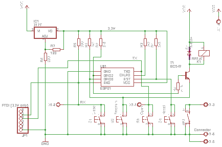
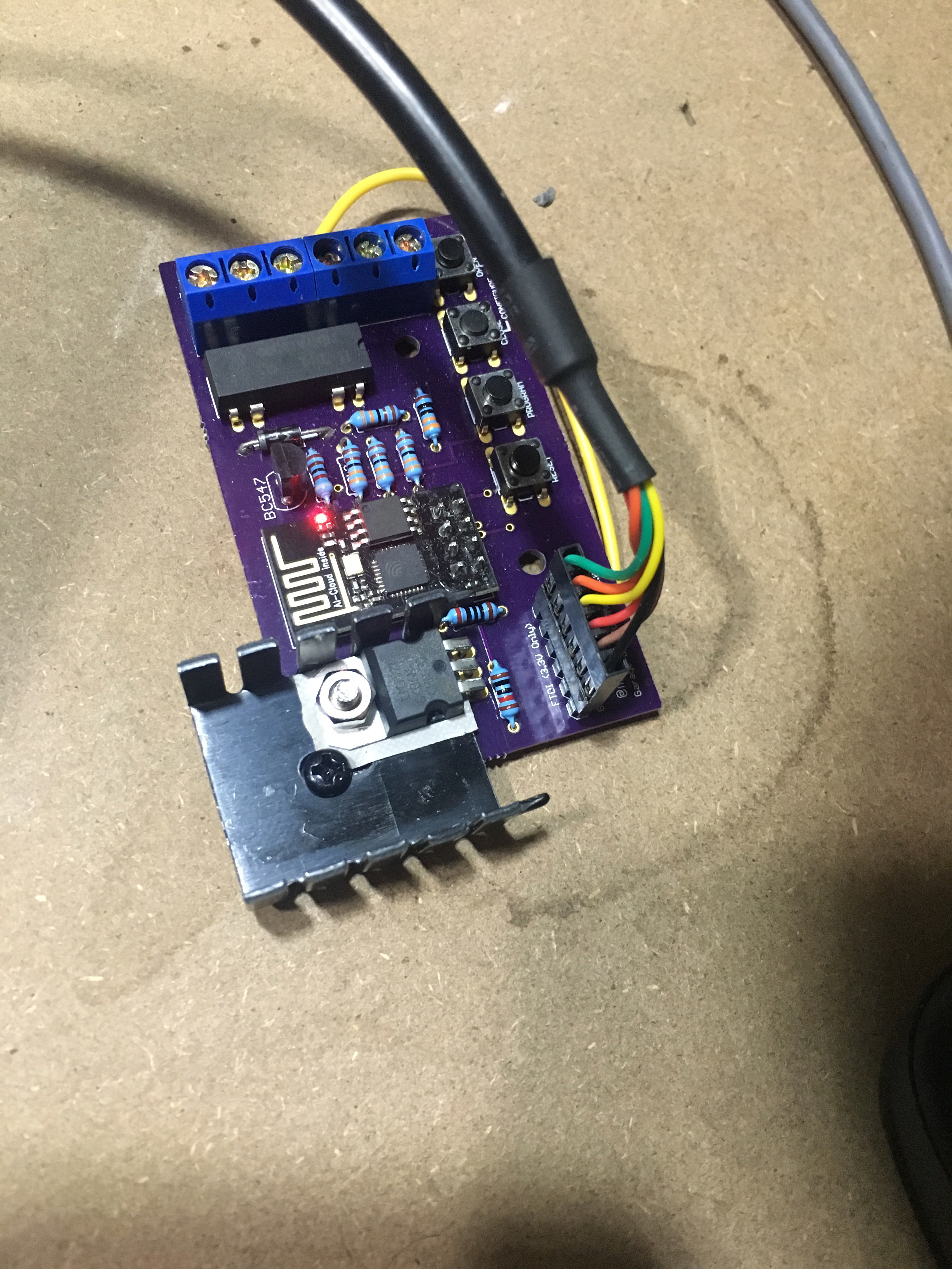
You do not so much need a heatsink, you need a step down regulator. :-)

If you want to stay with the linear approach then you could improve your calculation of the thermal resistance.
* At first do not use an "average" ambient temperature, use the worst case, that is the highest temperature you want your device to work reliable. Lets say 40°C. Take a rise of the temperature in the enclosure into account.
* Second take the internal thermal resistance of the package (junction to case[bottom, mounting plate]) into account, but that is only 1.1K/W for the TO220.
* Then take the maximum allowable junction temperature, for the normal LM317 that is 125°C

Now you get an allowable rise of the junction temperature of 125-40=85°C. With a dissipation of 2,784W you get an allowable sum of thermal resistances of 85/2,784 = 30,53K/W. From this you can subtract the internal therm. res. and additional 0,5 to 1K/W for the thermal interface materials (heat sink grease, mica or silicone). So your heatsink has to be 28,5K/W or better (Lower).

  Are you sure? yes | no

Myles Eftos wrote 03/22/2017 at 20:09 point

A step down would have been awesome, but I'm not good enough to tackle designing on yet (maybe next project!).

Thanks for the notes - I assume when you use K you still mean Celsius, not Kelvin?
I take your point on the max temperatures, and since that power output is a surge that only happens in startup, you are probably right about the heat sink being complete overkill. At least I can be confident I won't cook the regulator
Interesting reading!

  Are you sure? yes | no

Similar Projects

Does this project spark your interest?

Become a member to follow this project and never miss any updates