 Voja Antonic
I built my first logic analyzer in mid-80's. It was 10MHz 32-channel × 2K samples analyzer, with a complex triggering criteria and dedicated mainly to 8-bit processor systems. You could set the trigerring and sampling events, start it and watch the waveforms or execution steps of the target system, recorded at real time, without disturbing its execution.
For instance, you could connect it to the address and data bus (plus 8 external points) of the target system, preset it so that it triggers when CPU writes something to the specific address, and watch 256 samples of negative time (instructions which preceeded the "write" instruction) and 1792 samples of positive time, after the triggering event. The input interface was the 28-key keyboard, and the output was the monochromatic 50Hz monitor.
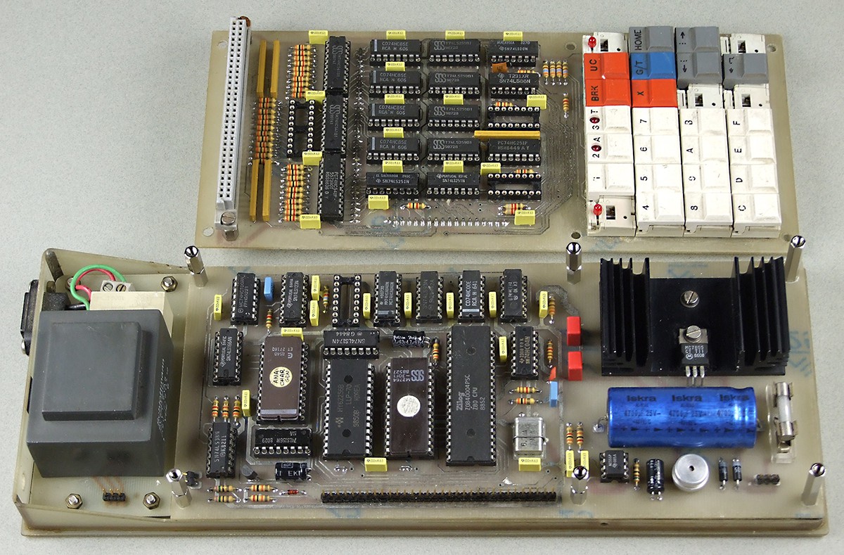
Now I have only a part of that project, two of three PCBs which were arranged in sandwich. The board with RAM and counters is missing, I guess that I reused some chips and dumped the board. But the Z80 PCB is here and almost complete. It also generated the video signal, aided by software.
In 1986, I wrote the letter (there was no e-mail at that time) to the BYTE magazine, asking to publish it as the DIY project. Soon I received the reply from the senior editor, which was very interested. Here is the scan of the first page:
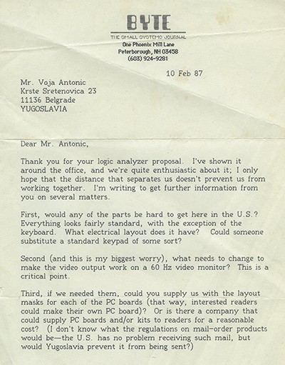
I made the detailed documentation of the project and sent it as the first version of the article. But the next reply was disappointing, I was told that Mr. Steve Ciarcia, who had his Circuit Cellar column in BYTE, did not allow the project publishing, as he was just preparing the similar project. I don't know did he publish his analyzer project, as it was very hard to get BYTE magazines here at that time.
Several years later, at the beginning of 90's, I built the remake of my analyzer. It was conceived as the card for 8-bit ISA slot of desktop PC. I was still at DOS level, so I wrote the software in assembly language, with 640×480×16-colours graphics. There were 43 SSI and MSI ICs, five 32K×8 static RAMs and one PIC16C54.
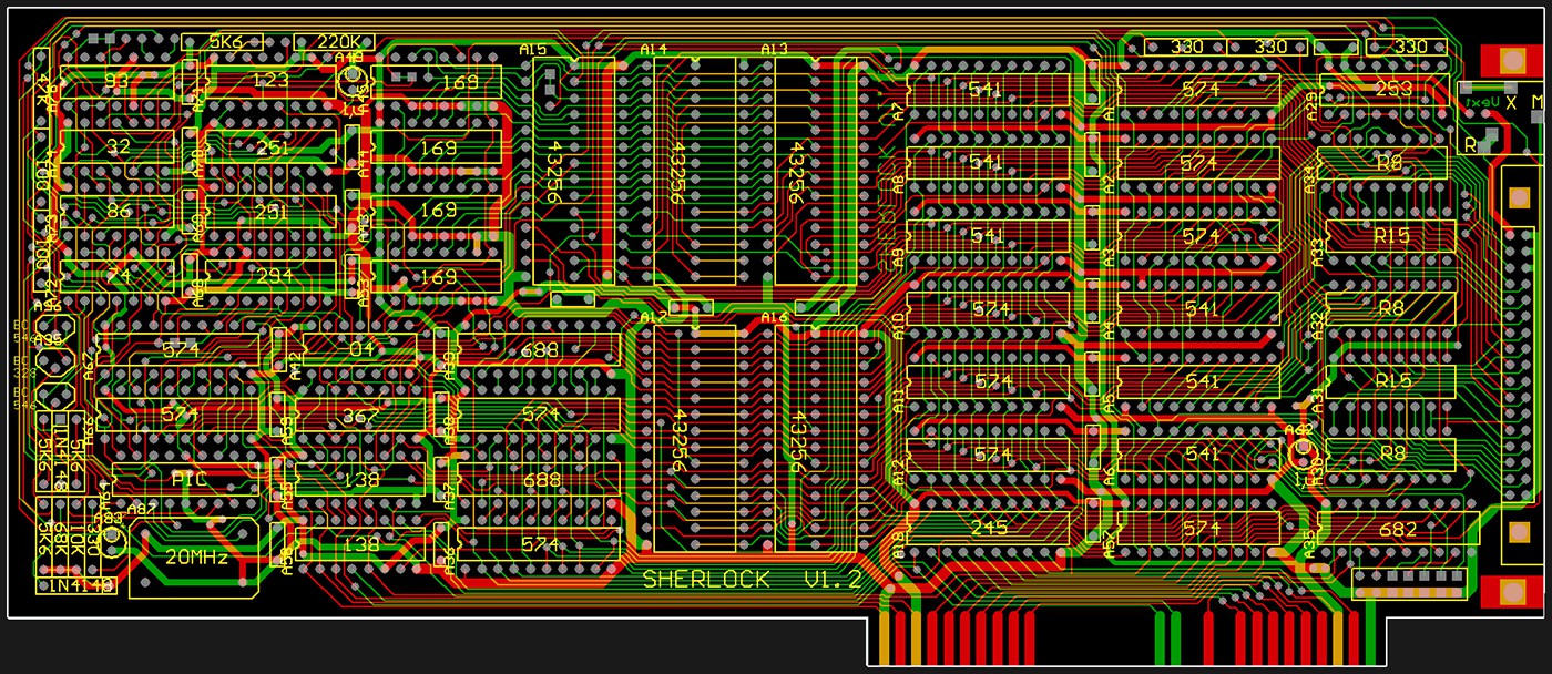
The sampled word was reduced to 24-bit, but all other capabilities were mainly the same. One or two inputs could be used as general purpose inputs, depended on how wide address bus you needed. Unfortunately, I don't have it any more, all I have is the first photo in the project gallery and a few PCBs. I still have the software (including source files and several sample files), but it can not run on new 64-bit platforms. So, the following screenshots are actually taken by camera, as I have no computer which accepts the software, and can create the screenshot image at the same time.
This is the main screen, with the window "options" opened:
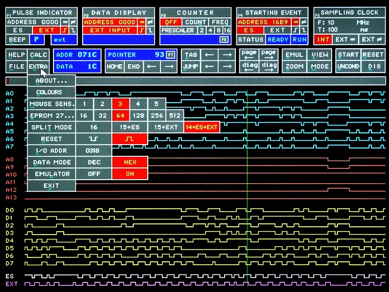
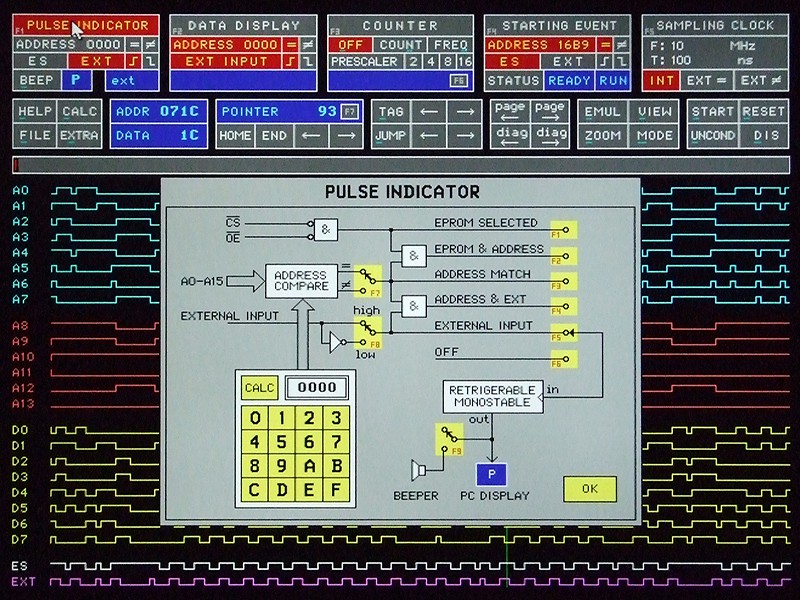
There are several graphical menus used to select parameters and modes. This is the audiovisual pulse indicator, used to indicate some hardware conditions (for instance, if CPU executed some instruction or some memory location was read or written). You could change the state of any switch by clicking on its graphic representation (yellow areas). So the schematics was actually animated:
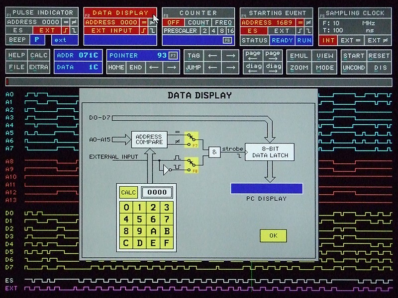
The next one is data display, where you could follow the contents of some RAM, I/O or program memory location in real time
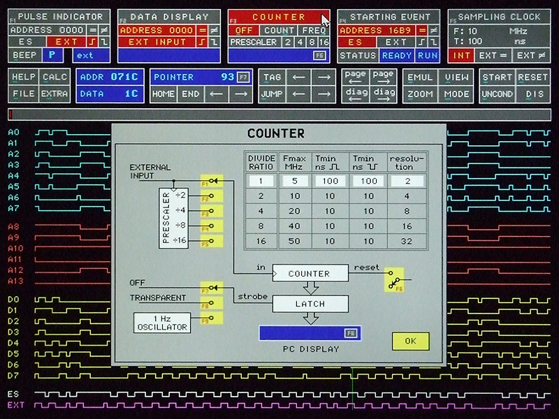
There is the frequency or external pulse counter, which runs in counter, frequency meter or transparent count mode
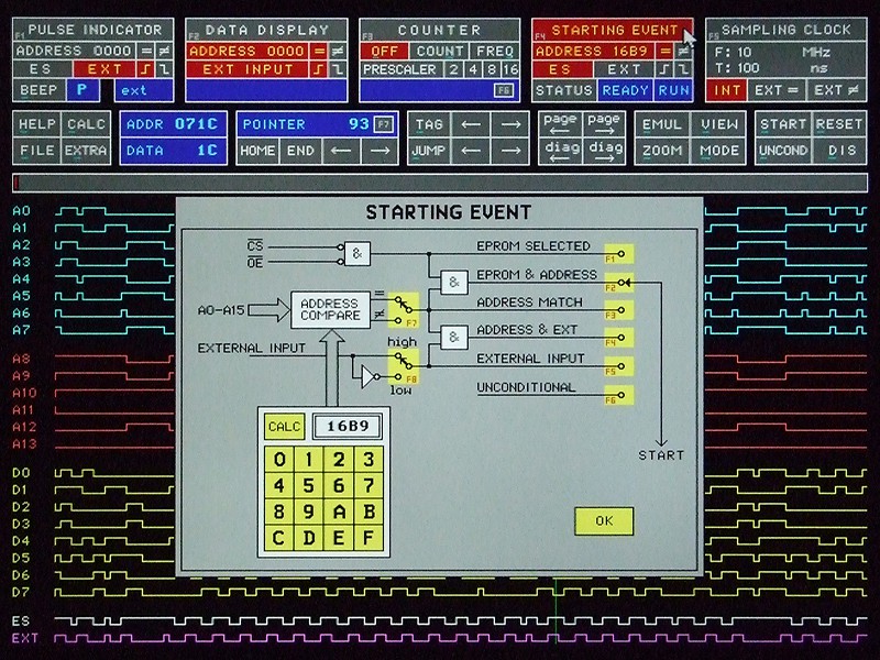
The main trigger event is flexible, so it enables start of sampling process by reading or writing to some addres location, or external trigger
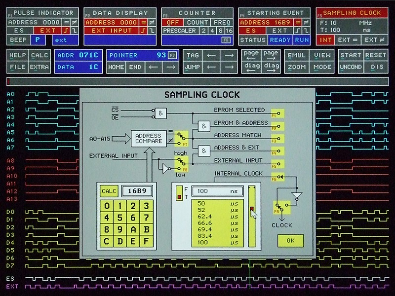
Sampling condition can be uniform clock in wide range, or external signal (read/write from/to any or some specific address, or any combination.
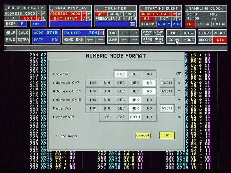
If you watch the sampled data in numeric mode, you can select the display mode for any column of data individually, and also to see which condition triggered the sample
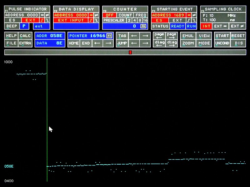
Oscillographic mode is convenient for program flow following. You can see the graphical representation of every executed and sampled instruction
This is the same sampled program sequence, but in the...
Read more »


 Blair Vidakovich
 Ted Fried
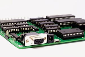
 Anders Nielsen
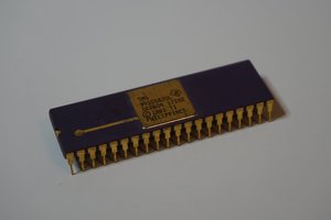
 Erik Piehl
Yet another impressive project... Congrats !