 Dan
DanI created this project as a sort of follow up to my Arduino BASIC Shied project which used a custom designed shield to turn the Arduino UNO into a computer running the BASIC programming language. The shield worked correctly but two reasons made me decide to design a new computer; the TVout resolution was low meaning some of the lines were wrapped onto next line and an Arduino was required to operate the computer (it was not entirely standalone). I decided to design a new computer which would still run BASIC but use only a single AVR microcontroller to keep circuit design simple, the component count low and the cost down.
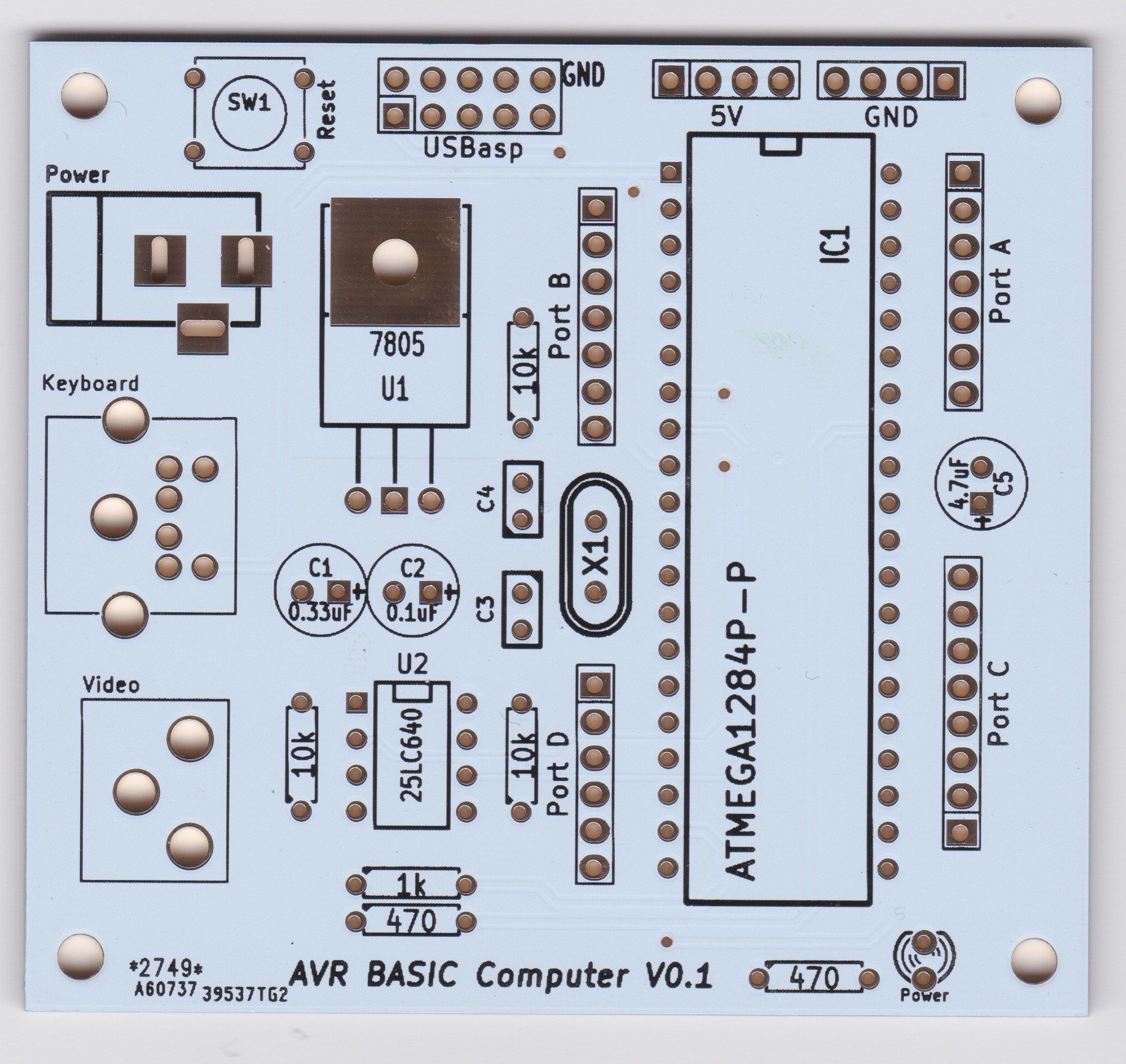
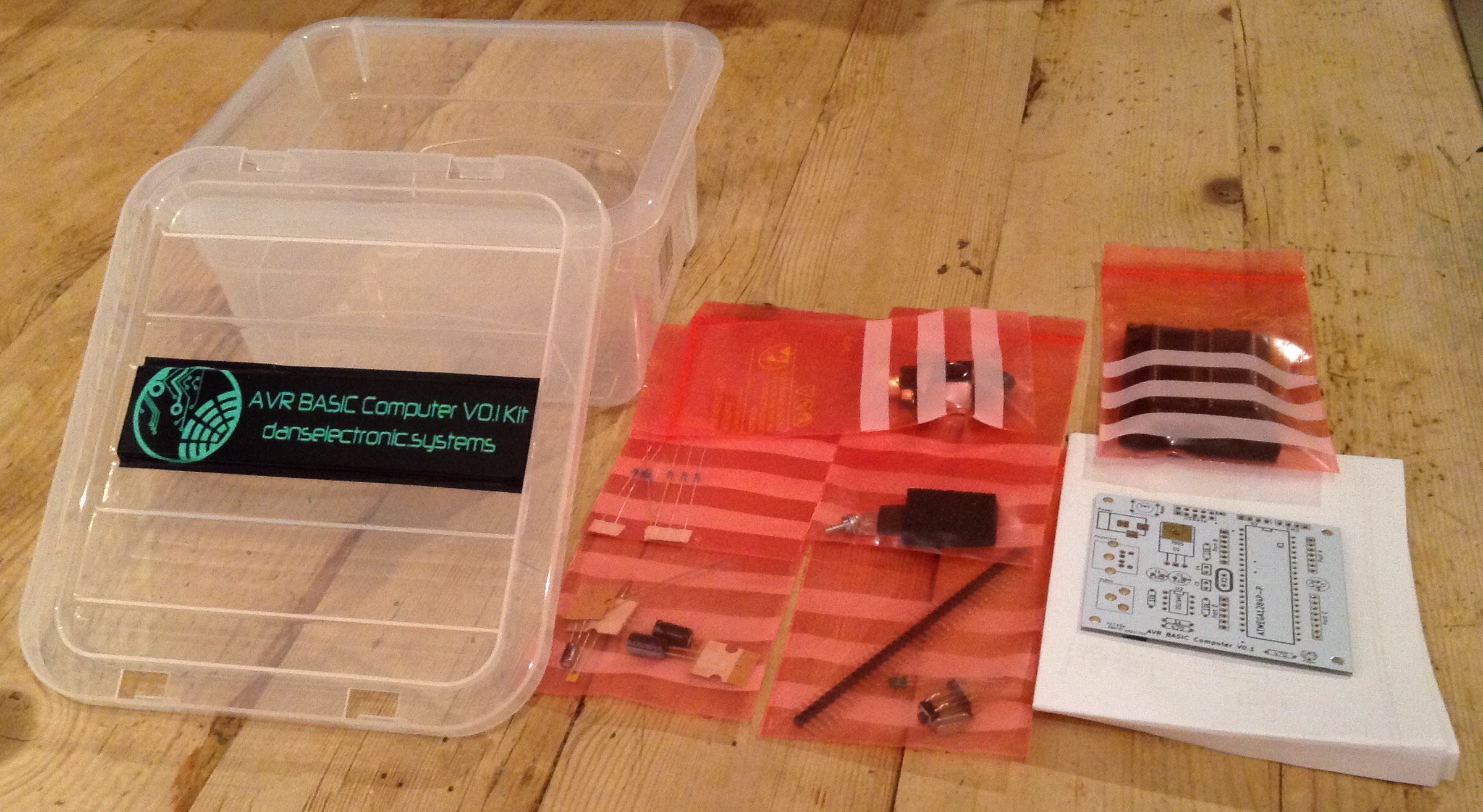
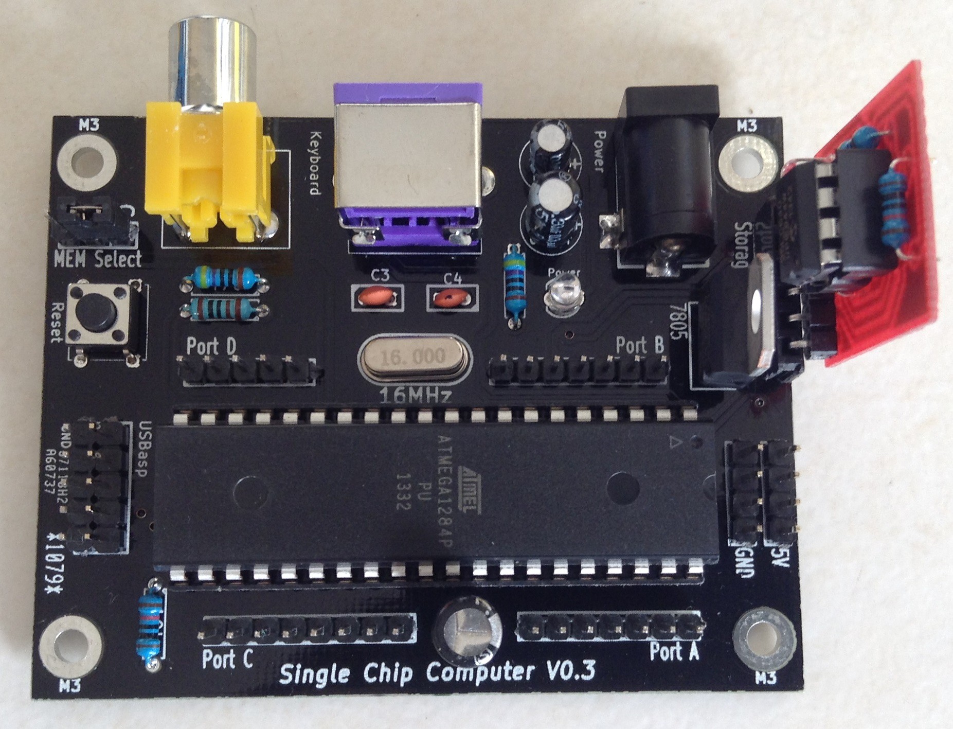
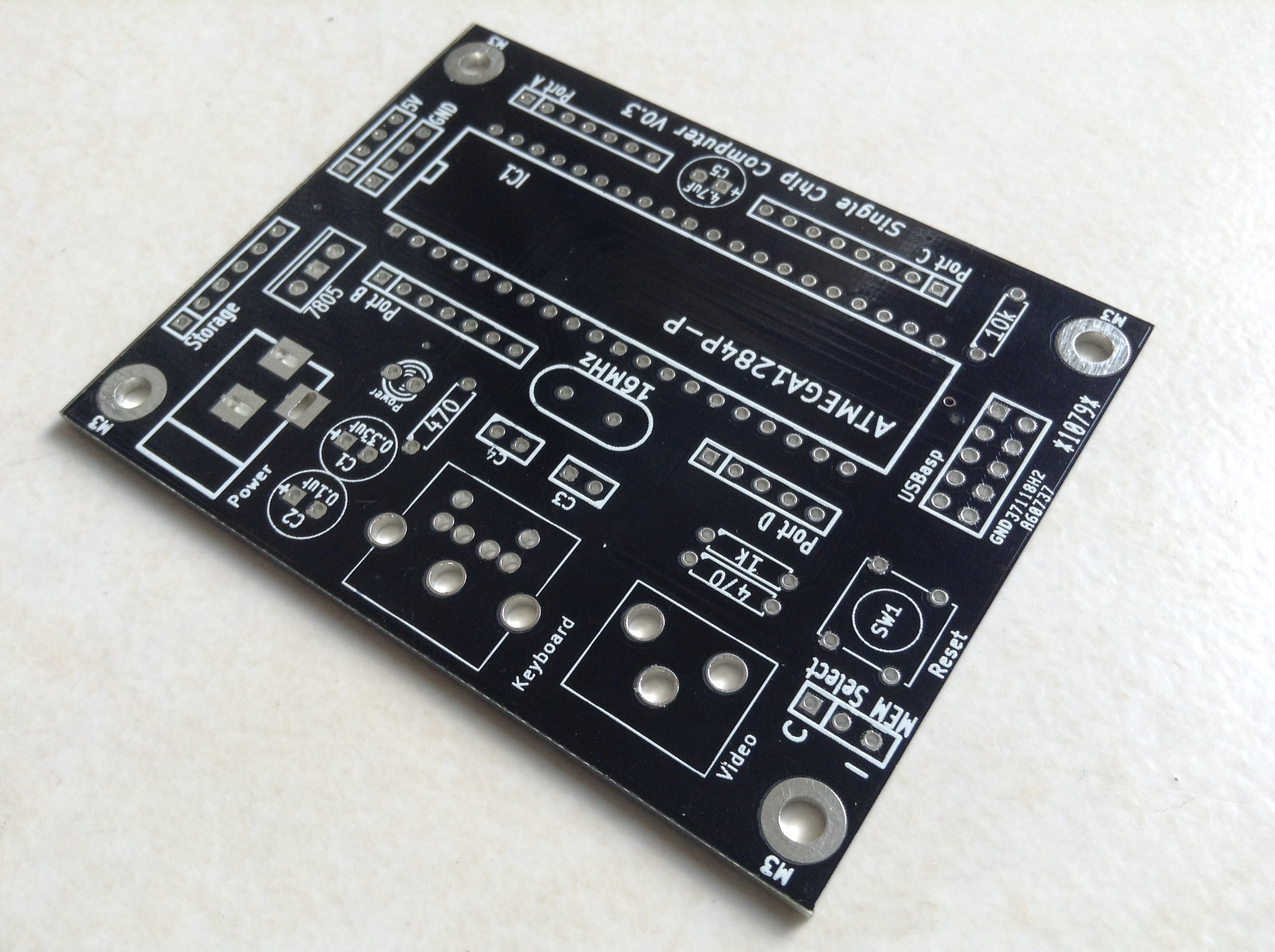
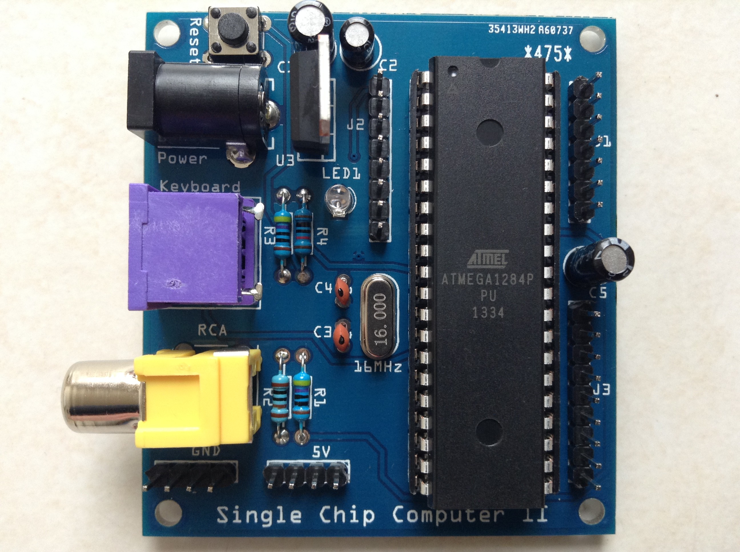
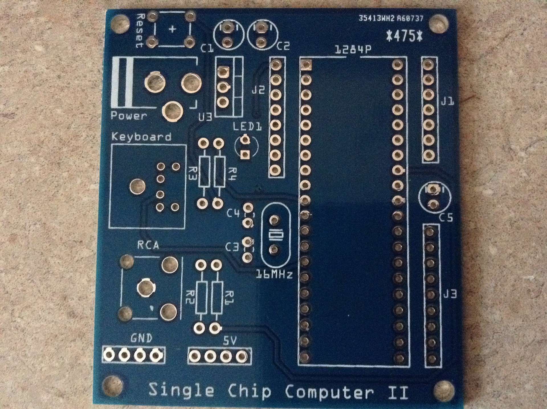
After managing to find a PS2 keyboard library which worked with TVout without causing any issues, I modified the TinyBASIC Plus sketch to use TVout and the PS2 keyboard (rather than serial) and tested it the ATmega 1284P (I am using the Arduino bootloader and IDE to program to the 1284P) which worked correctly. It was then a simple case of designing a PCB and sending it off to be manufactured. I was able to keep the PCB single sided by using two jumper parts (two 0 ohm resistors). The build instructions on this page explain the process of building the computer step by step.
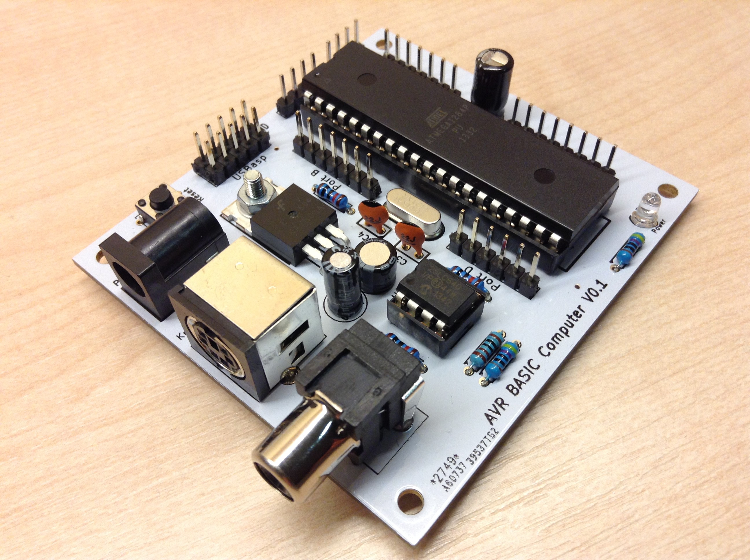
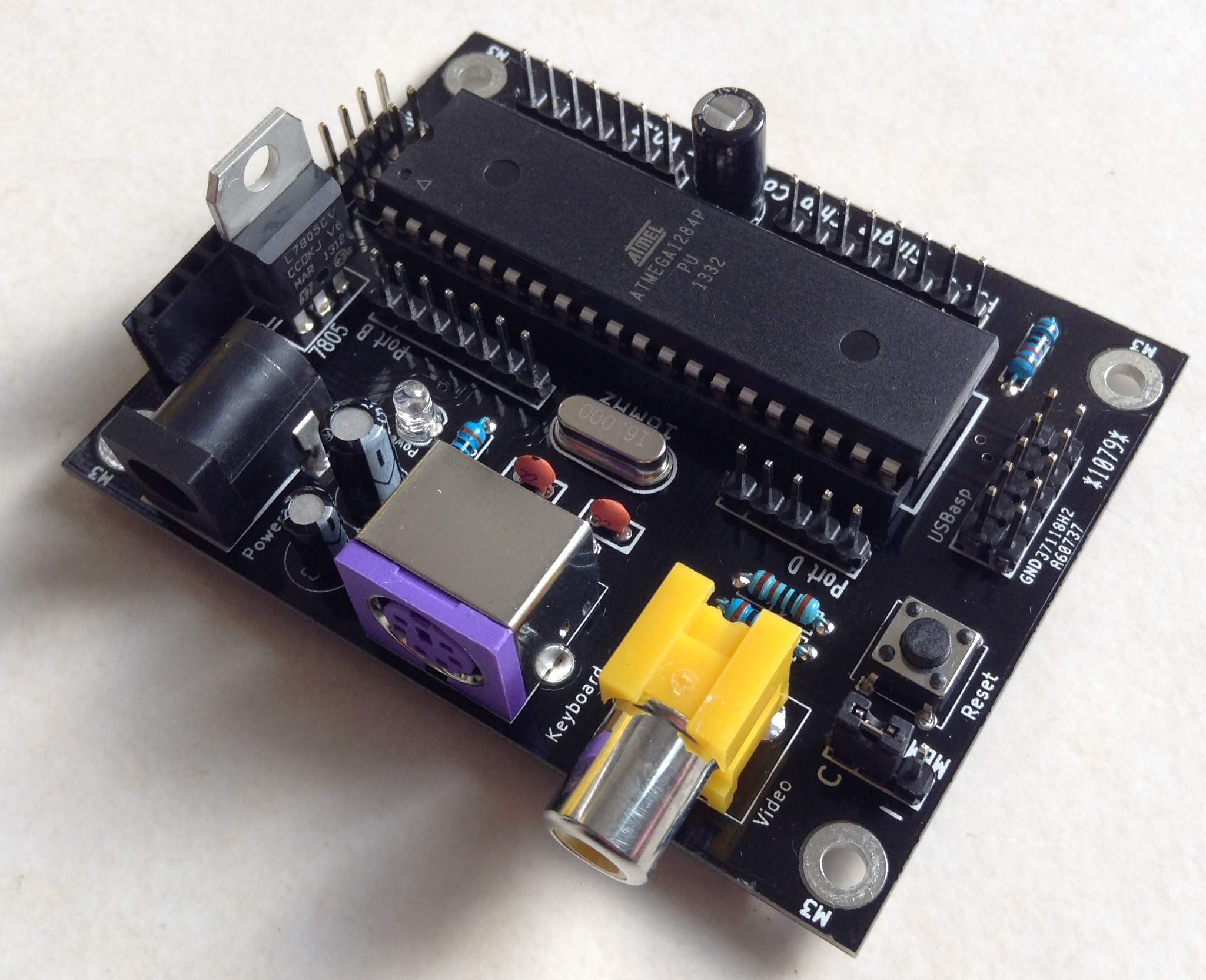
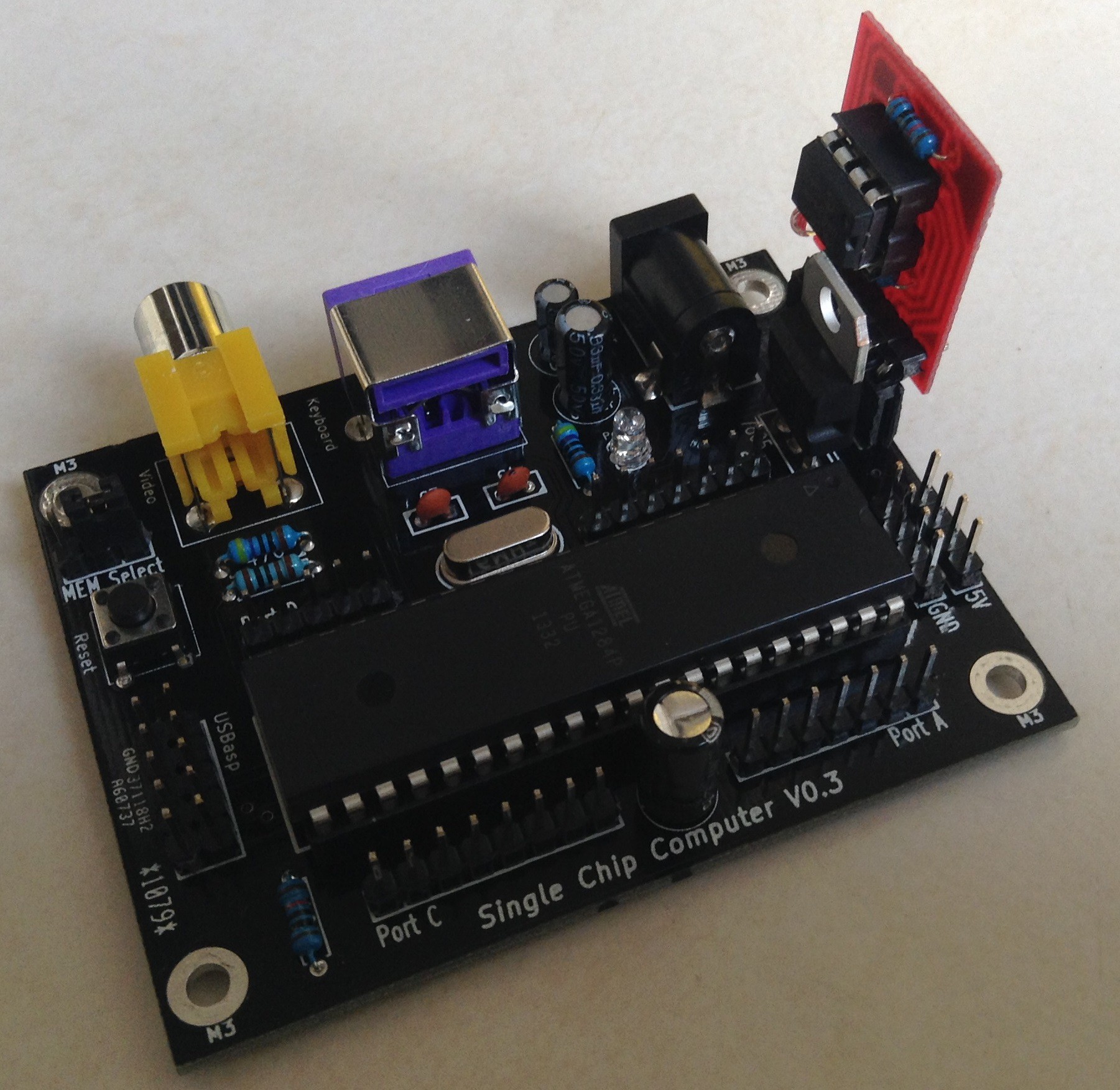
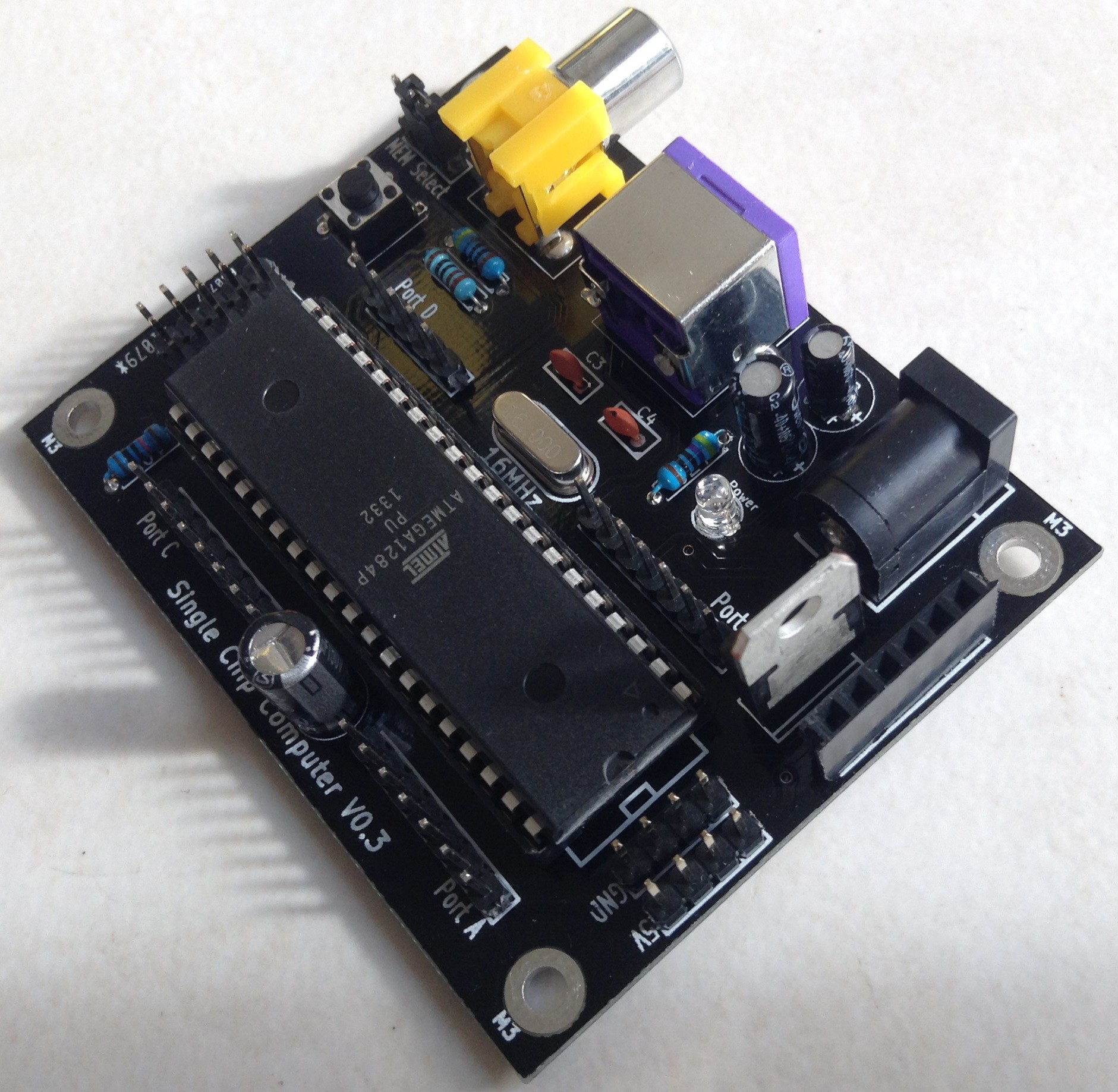
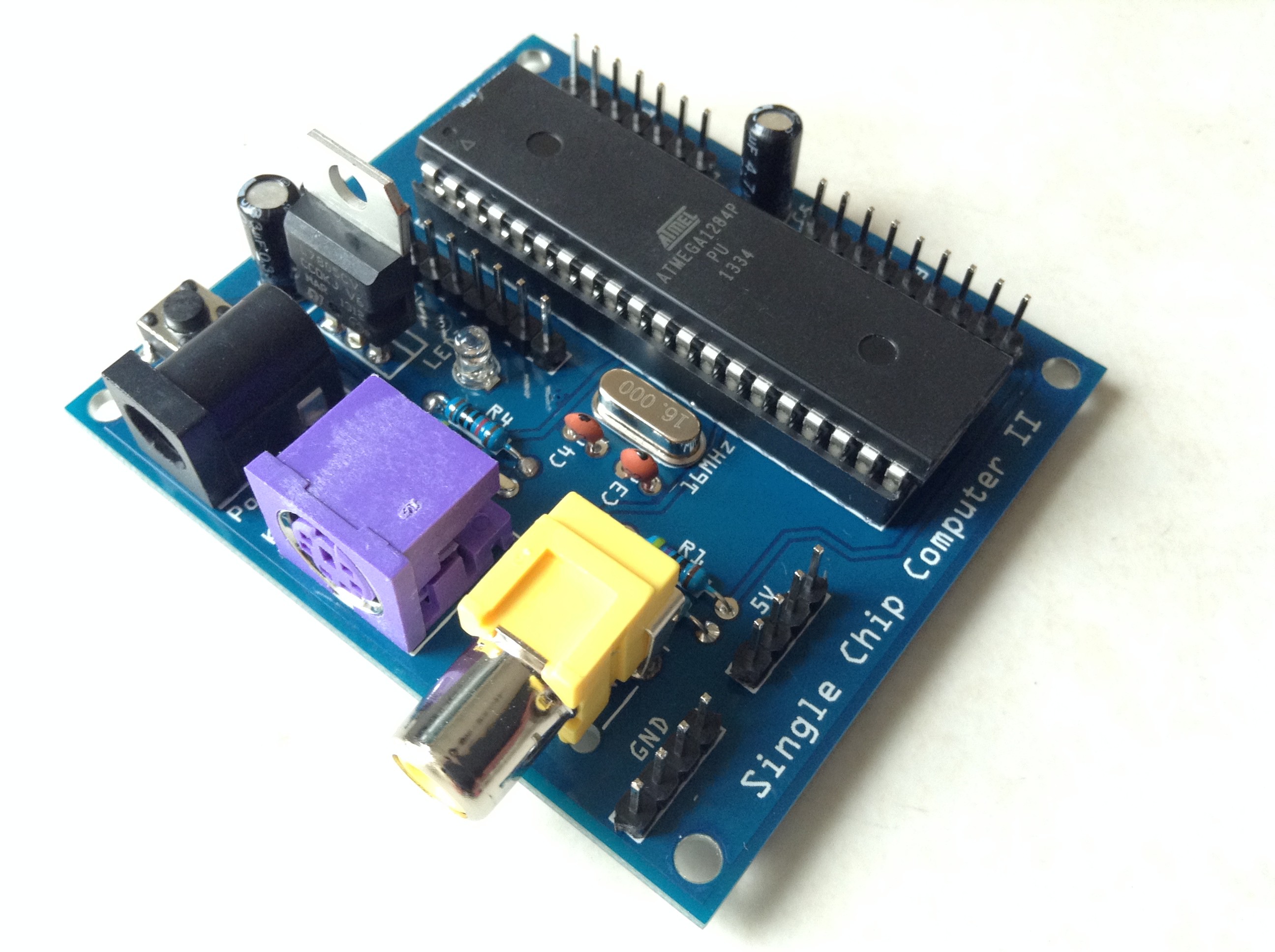
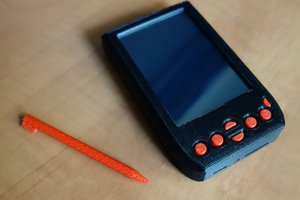
Once the computer had been completed, I had a functioning standalone system which uses a single AVR microcontroller.
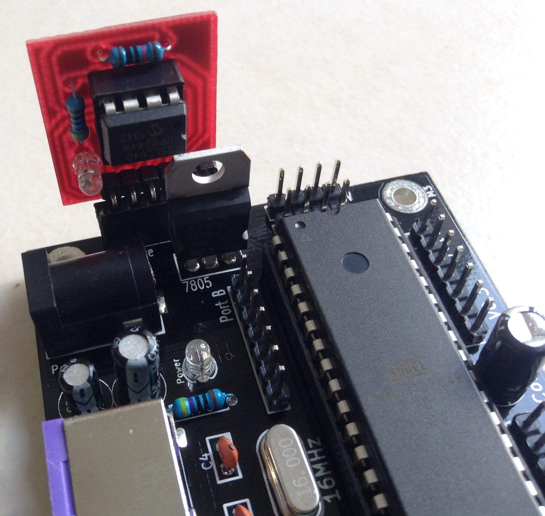
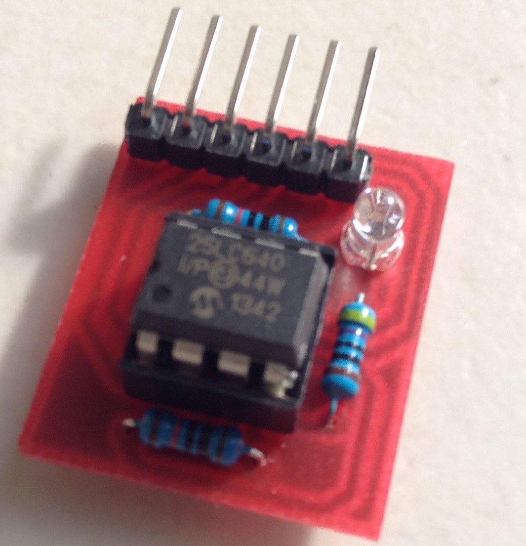
The computer has some of the GPIO pins of the 1284P mapped to female pin headers allowing components to be connected. Pin headers are also used to allow the power supply rails to be connected to. By connecting a PS2 keyboard, composite video enable display (such as a TV which has a yellow RCA socket) and a power supply (such as a PP3 battery), the computer can be used and programmed in BASIC. The EEPROM of the 1284P is used to save the BASIC programs to.
Ideally, I would like to have included an SD card for program storage but I was having issues with the FILES command (the TinyBASIC command) displaying random characters on the TV. Autorun BASIC programs are found and run fine (when an SD card is attached) but the FILES command does not show a list of files on the SD card like it is supposed to (rather the random characters). I am unsure of the issue which is causing this (it may be linked to the variable types used to store the file names and the different variables used by TVout but I am unsure) so I did not include an SD card. If this issue was fixed, I would include an SD card on a future version.
In summary, I have been able to create a standalone computer system running the BASIC programming language with composite video generation and PS2 keyboard reading using only a single AVR microcontroller.


 brtnst
 C. Scott Ananian
 Patrick Thomas
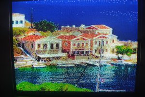
 Leon
Leon
how long this device work?
month? on AA or more?