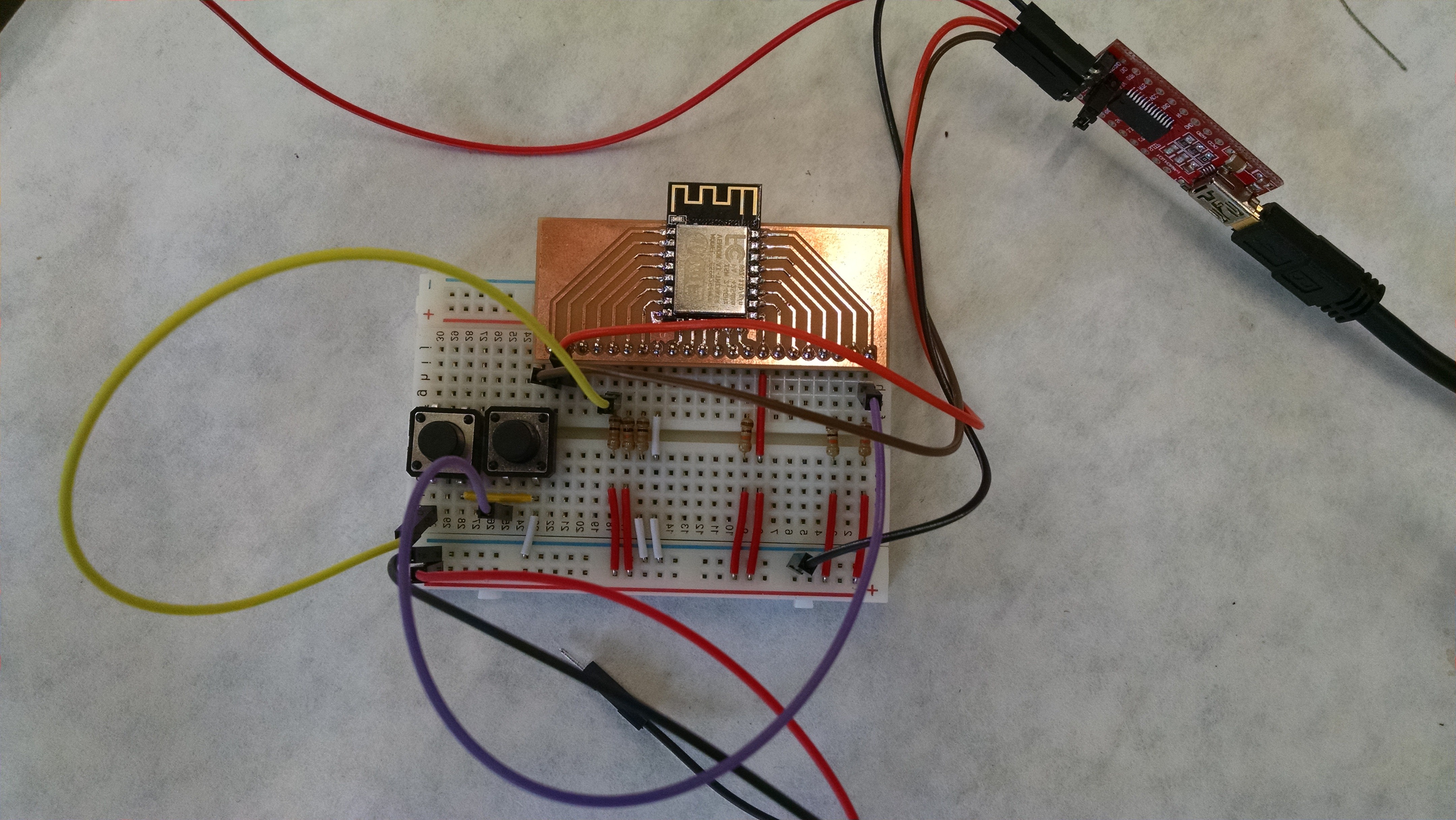
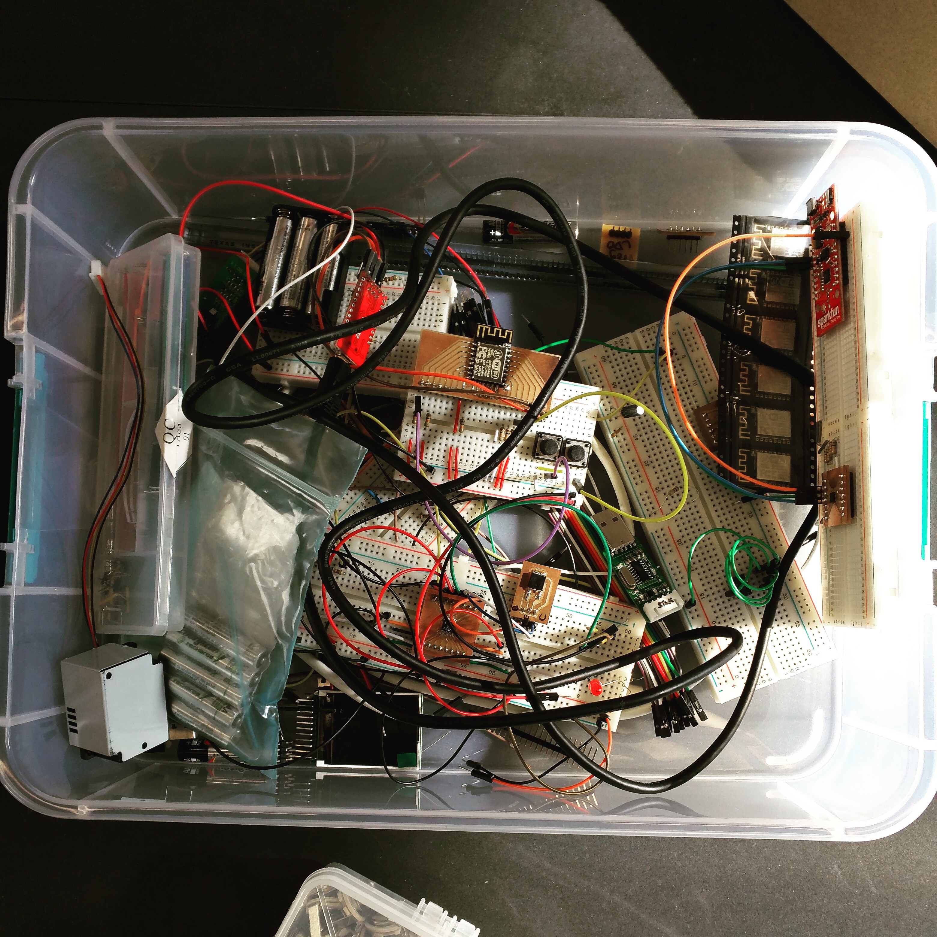
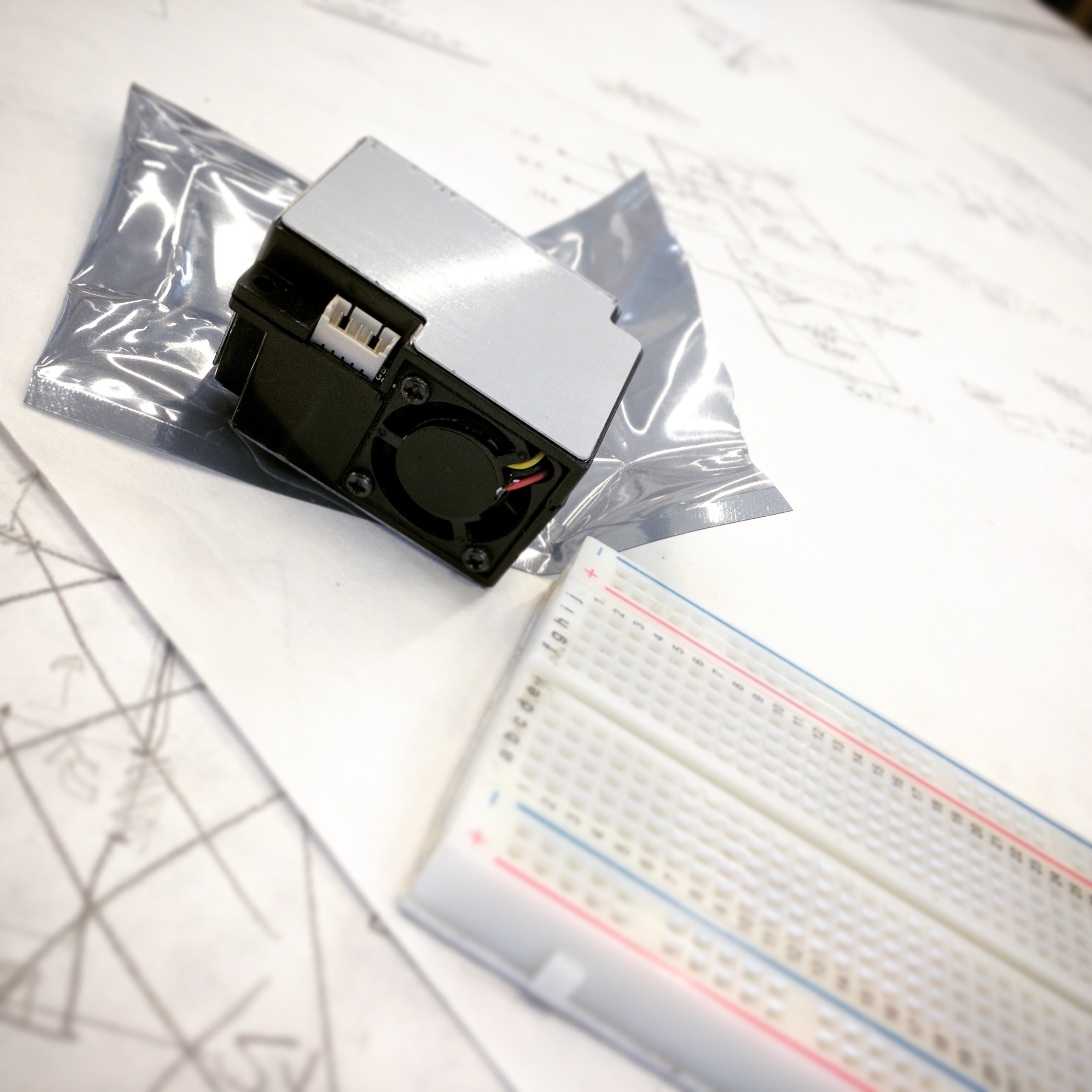
• Designing a REST API

    Chris Del Guercio09/22/2016 at 17:39 0 comments

    This week I spent a good chunk of time designing the spec for the sensor data REST API. The API has been designed to be used not only by our product, but also by other sensor products. The main goals of the API are to 1) provide a simple yet powerful interface for sensors to upload data and 2) be designed so that every useful way that someone would want to query the data can be done efficiently.

    Above is the awful diagram that I crammed into a Google Slides page. The top starts with the Platform and Sensor tables, which formalize the sensor platform and the actual sensors within the platform. For example, Scintilla's product would be a Platform, and the SPEC sensors that we are using would exist in the Sensor table and be referenced by our Platform entry. A Deployment is a user defined group of Devices. This would be useful for instances where a user would want to aggregate data from many devices in either a consolidated dashboard view, or in a downloaded report. The Device table holds references to actual devices in the field. Each Device has a private device key that it uses to authenticate the data that it sends to the server. We take data integrity very seriously and our resident computer security PhD student Eric Gustafson is working on making sure that the device keys are safe from prying eyes. Readings represent the raw readings that the sensor takes. They can be point values or averages and they can be of any unit. Readings taken at the same time are sent in bundles called ReadingGroups. These groupings can later be utilized to calibrate many readings against each other to compensate for things like cross interference or temperature and humidity skewing the data. For instance, a device might send out a ReadingGroup that contains one Carbon Monoxide Reading, one Temperature Reading, and one Nitrogen Dioxide Reading. It could be the case the the CO sensor has a known cross interference with NO2, so the CO Reading might be decreased based on how much NO2 was detected. In addition, both CO and NO2 sensors likely have documented biases that change with temperature, so those Readings could be calibrated against the Temperature Reading. How Readings are grouped is completely up to the client. CalibratedReadings are Readings that have had post processing done on them. How this is done is also completely up to the client.

    This is only v0.1 of the API. The next step is to get our product communicating with a server using this API and see how it works in practice.

  • Milling a Breakout/Flash Board for an ESP-12-F (ESP8266)

    Konrad R.K. Ludwig08/23/2016 at 17:59 3 comments

    UPDATE: The schematic used in the original post could not flash the ESP-12F firmware. I have updated the schematic in this log with a corrected version that includes the necessary pull-up/pull-down resistors, however the photos for the log still show an incorrect version of the schematic.


    My first run in with the ESP-12-F module wasn't pretty. I bricked the first one with a 5v goof and couldn't get the other to work because I rushed the soldier job and created an intermittent short across some of the pins. After a few days I was so frazzed I surrendered to the IC, let Chris sort things out and set out to find a better way by milling our own breakout board.

    My goal with this mini-project was to get familiar with two-sided PCB design and assembly and to create a simpler way to flash and rapidly test code on our ESP-12-F module. In essence, I wanted to recreate Chris' flash circuit with integrated switches and buttons.

    he circuit is relatively simple. I managed to cut down the resistor count to a whopping one 10k ohm pull-up resistor on the reset pin and integrate some push buttons and a line selector switch. The line selector switch is essentially a power switch, while the buttons are used to reset and flash the ESP8266.

    The actual circuit design was a bit trickier, due mostly to the compact design of the ESP-12-F module. The good news is that you can pick up footprints for almost every ESP8266 module on GitHub, however. The repository only had an ESP-12-E, so I added my own modified footprint for the ESP-12-F with some renamed pins. (I have a plan to submit a pull request, I promise!)

    Because the layout of the pins on the ESP-12-F is a little wonky, one of my main goals with this design was to group the various pins according to what they do. All the GPIOs are bunched together on the left in the order they wrap around the board. The primary UART pins are on the top right, with their own grounding pin, the I2C/TWI pins are in the middle right, and main power and ground pins are on the bottom left.

    Milling the board was pretty straight forward, even though I forgot to measure the thickness of the material and tape the first time around. By the time I milled the second board (shown here) I got a much cleaner job out of the machine.

    The final product was a bit of a pain to solder together because of all the vias in the design. To make them bridge from the front to the back I used some spare breadboard resistors, fed the leads through, soldered each side and cut them down to size. Finally, I went over everything with a micrometer and verified the connections were solid.

    Once the entire board was assembled I plugged it into a USB/TTL module and fired it up. I'm not sure if my USB port can handle the power requirement to run this sucker, but I'm sure I'll find out soon enough when I start flashing it for real.

    Making sure my serial monitor was set to 74880 (the ESP8266 boot loader baud rate) I turned her on and tested the reset and flash buttons.

    That first message ("waiting for host") was a naked reset, the second stream of information is from the ESP8266 booting into flash mode and that last line of gibberish is just the device standing by on a different baud rate.

    So what does all that mean?

    She works! Now it's time to start flashing some custom software onto her beautiful 4MB of flash memory.

  • Battery Charger & Getting The ESP-12F To Flash

    Chris Del Guercio08/19/2016 at 22:42 0 comments

    Breadboarding up the LTC4060 multi-chemistry battery charger was probably the gnarliest wiring challenge I've had thus far. Since I was dealing with power I was extra careful to follow the schematic that I had created based on the data sheet. When I finally had it all set up and I attached my 3-cell battery pack (that I had discharged with a resistor the day before) and then set my power supply to 5V... nothing happened! I then turned everything off, rechecked all the connections, and looked over the data sheet again. Aha! If you set the LTC4060 to 3-cell mode, it requires 7.2V from the power supply! Once I brought of the voltage, I saw the red LED light up to indicate that the system was charging. The system seems like it was in slow charge mode, when I was expecting fast charge, but I can figure that out later.

    Getting the ESP-12F module form of the ESP8266 to flash was a little more complicated than the dev module. We had to set a few of the GPIOs to high or low with the buttons and use the reset to put the module into "UART download mode". Once we figured that out, flashing it using the Arduino IDE was a piece of cake. Next up is to build our own firmware capable of doing OTA firmware updates.

  • The SDS-021: An Homage to Cheap Chinese Docs

    Konrad R.K. Ludwig08/18/2016 at 18:15 4 comments

    Picking and sourcing sensors has been one of the major challenges we've faced with the Scintilla project. Back when our device was just a simple proof of concept, we could rely on some pretty cheap sensors to do the job. Once we got access to the SupplyFrame DesignLab, however, we devoted our time to converting our really basic NASA SpaceApps hack into a full-blown commercial grade air quality sensing IoT device that can generate some bang-on data.

    This quest for quality led us through about a month of research before we could mill a single breakout board. In the past few weeks, however, we finally started crawling away from of our digital pile of schematics and datasheets and started wring up our components into working sensors.

    Today I'm here to talk to you about one of our sensors in particular: the SDS-021 laser dust sensor made by the Chinese manufacturer Inovafitness. Without going too deep into the muck, the SDS-021 is an actively driven laser dust sensor designed to give accurate readings of PM 2.5 and PM 10 sized particles. It features a long use life, a power saving sleep mode, a query-based reporting system and a few other bells and whistles, all available through a simple-to-user UART protocol.

    Or so they say...

    Sure, you can say the SDS-021 has a "datasheet", but it's a real case study on the limitations of sourcing things from China. Aside from some poorly translated English paragraphs advertising what the device can do, there is very little in the way of how to get the device to do it. The limited instruction it does give is sometimes wrong -- like the checksum calculation, for example. Finally, the specification ends on something of a cliffhanger when it lists a bunch of "extended features" in a friendly bullet list and doesn't follow up with anything else.

    I tried contacting somebody over at Inovafitness for better docs, but I don't speak Chinese and something told me the email address "79557362@qq.com" doesn't get checked very often. After two days of waiting for some kind of reply, I finally decided to roll up my sleeve and take a shot at some good old fashioned reverse engineering.

    My hope was that we could find some kind of program or diagnostic utility that can communicate with the SDS-021. Luckily, If you crawl around the Inovafitness site (like I did), you will eventually stumble across a desktop utility for working with their sensors. This was a gold mine, but it didn't list the SDS-021 as an available sensor and it's not designed to work with Windows 10 -- which meant it didn't find any of COM ports I had plugged in.

    To work around these problems I had to run the application in compatibility mode for Windows 8 and take a guess that the protocol for the SDS-011 or the SDS-018 (the previous two versions) were the same as the SDS-021. Well, it turns out the SDS-018 didn't work, but the SDS-011 started up without a problem, so the next step was to get some data and play around with the sensor.

    Playing around is an important step. First off, it's playing. Secondly, it allows us to answer important questions. For example, what happens if you query the state of the sensor while it's sleeping? Turns out the sensor wakes up all of a sudden and sends some bytes that basically mean, "I'm up! I'm up!" while it wipes the drool off its face. Below you can see a screenshot of the sensor in its default mode, spamming the COM port with data every second.

    The next step was a little more boring and tedious: I had to sniff the COM port, click a bunch of buttons and work through every conceivable device state I could think of and keep track of the changes. Eventually I managed to figure out all of the different commands, what they do and how to make sense of the replies the device sends back.

    Once I had all of these instructions in the bag, I hacked out a library to drive the sensor with an ESP8266 micro-controller and gave it a whirl. Once I was convinced everything was working right, I changed the status from "In Progress" to "Completed"...

    Read more »

  • Short Week

    Chris Del Guercio08/09/2016 at 22:50 0 comments

    Not a lot to talk about this week since I left for Las Vegas Tuesday night to attend Def Con 24. Before I left I managed to solder a few of the components to the breakouts and tested them with an Arduino. From left to right we have the SKM61 GPS module, the MJD210 transistor, and the MCP3425 ADC. Each component is accompanied by a corresponding Arduino .ino named using the "<component>_test" convention. They can be found here: https://github.com/scintilla-aircheck/scintilla-arduino-projects

  • First Digi-Key Shipment & Breakout Board Fun

    Chris Del Guercio08/09/2016 at 22:20 0 comments

    This week our GPS modules and our first Digi-Key shipment of components arrived. We decided it would be a good idea to make breakout boards for each component to prove that our footprints are correct.

    The GPS module was a particularly hard component to make a board for since the underside of the board sticks out below the plane and therefore necessitated an inner cutout. We also needed to make extra pads for GND on the left and right sides of the board. Apparently this is a technique that helps with interference against the GPS antenna. Since the pads are hidden under the board, we had to use solder paste and a hot air gun to make all of the connections.

  • Attack of the Sensors!

    Chris Del Guercio07/22/2016 at 22:25 0 comments

    The big news this week was the arrival of our first batch of sensors. From left to right we have O3, H2S, NO2, SO2, and CO electrochemical gas sensors from Spec Sensors (http://www.spec-sensors.com/). Before we can start taking readings from them we have to acquire a potentiostat because these sensors output a varying current and we need varying voltage.

    In other news, I've started writing microcontroller code for the system that will take the readings from the sensors, record them onto an EEPROM, and then transmit them via WiFi to our web API. I've written some test code that utilizes an embedded implementation of Google's Protocol Buffers called NanoPB (https://github.com/nanopb/nanopb) to serialize the sensor data for temporary storage on the EEPROM as well as for transmission of that data to the python code that the web API is written with. Right now I have all this running on an Arduino, but we discovered this week that with some clever use of multiplexers we can probably run our whole system off of the ESP8266 WiFi microcontroller. I've put the order for a few of the ESP-12F surface mount packages which should arrive in a week or two.


  • Our first enclosure 3D print!

    Chris Del Guercio07/15/2016 at 16:54 0 comments

    Our first two weeks at the Supplyframe Design Lab have been very research heavy. We've been busy figuring out which sensors we'd like to include, emailing chip manufacturers overseas, choosing how power and internet connectivity are going to work, etc. So, to make things more interesting Kyle showed up to the lab to help model and prep for 3D print a prototype design of the sensor enclosure. The black colored filament contributed to a sci-fi looking enclosure. Konrad suggested that it looks like a sticky bomb from Deus Ex.

    Also, on Thursday, Robert de Groot of the Quake Catcher Network came to the lab to field our questions about sensor networks. The QCN is a network of seismometers that can be used in various applications ranging from early warning earthquake detection to education in K-12 classrooms. Robert had many insightful things to say about ways to move forward as well as potential pitfalls that we might come across in our project.