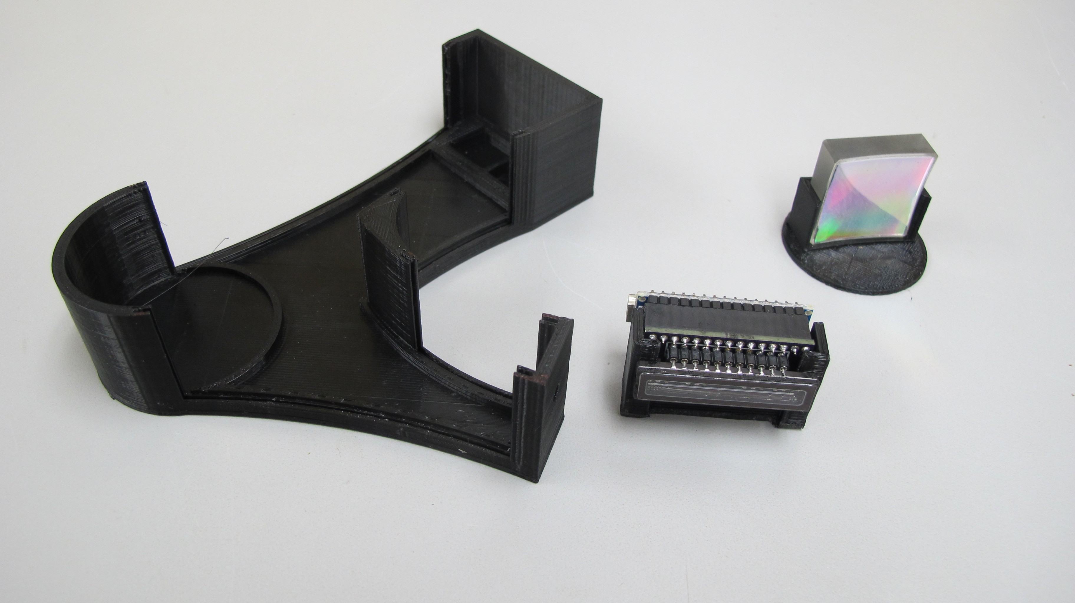
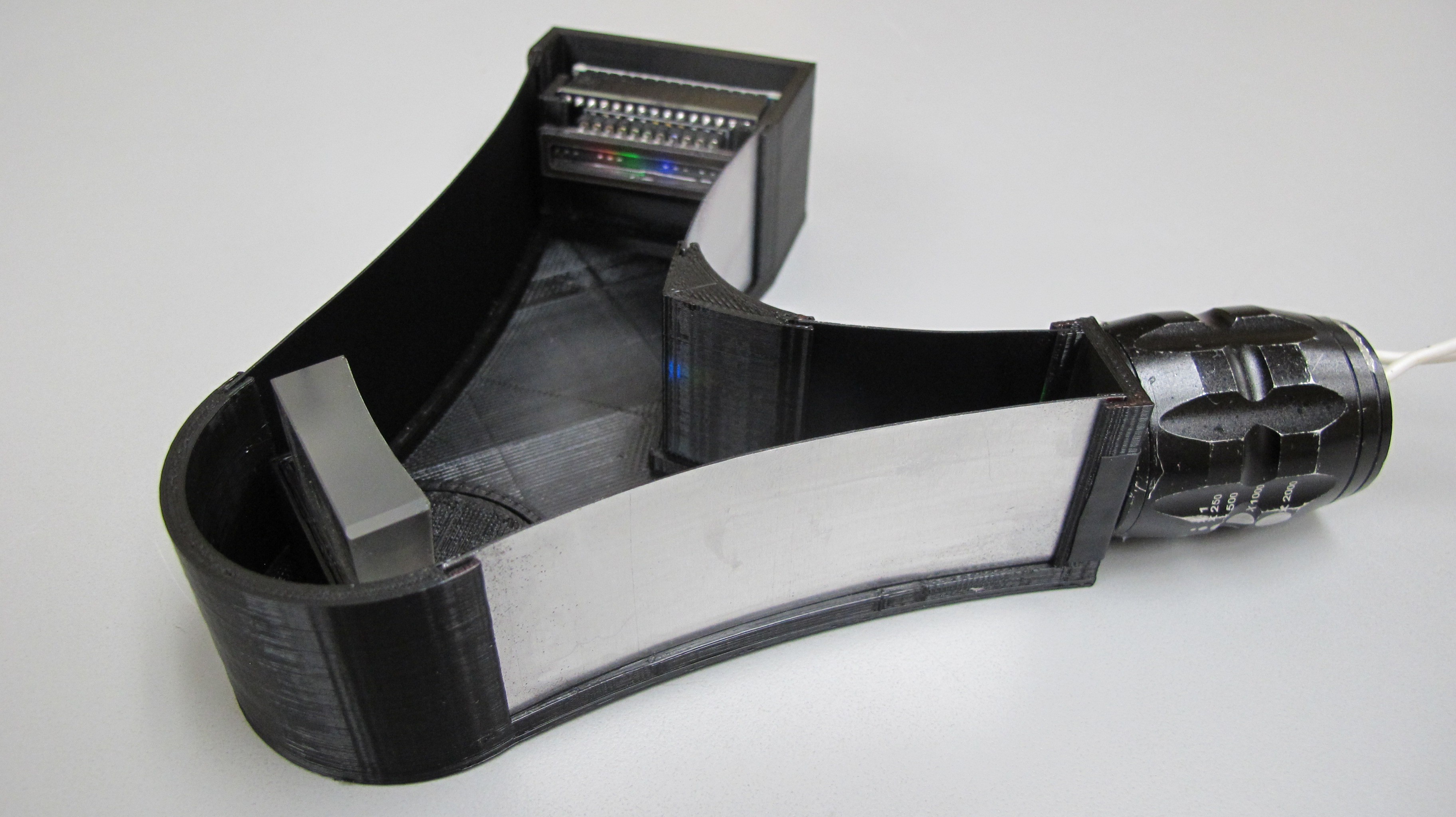
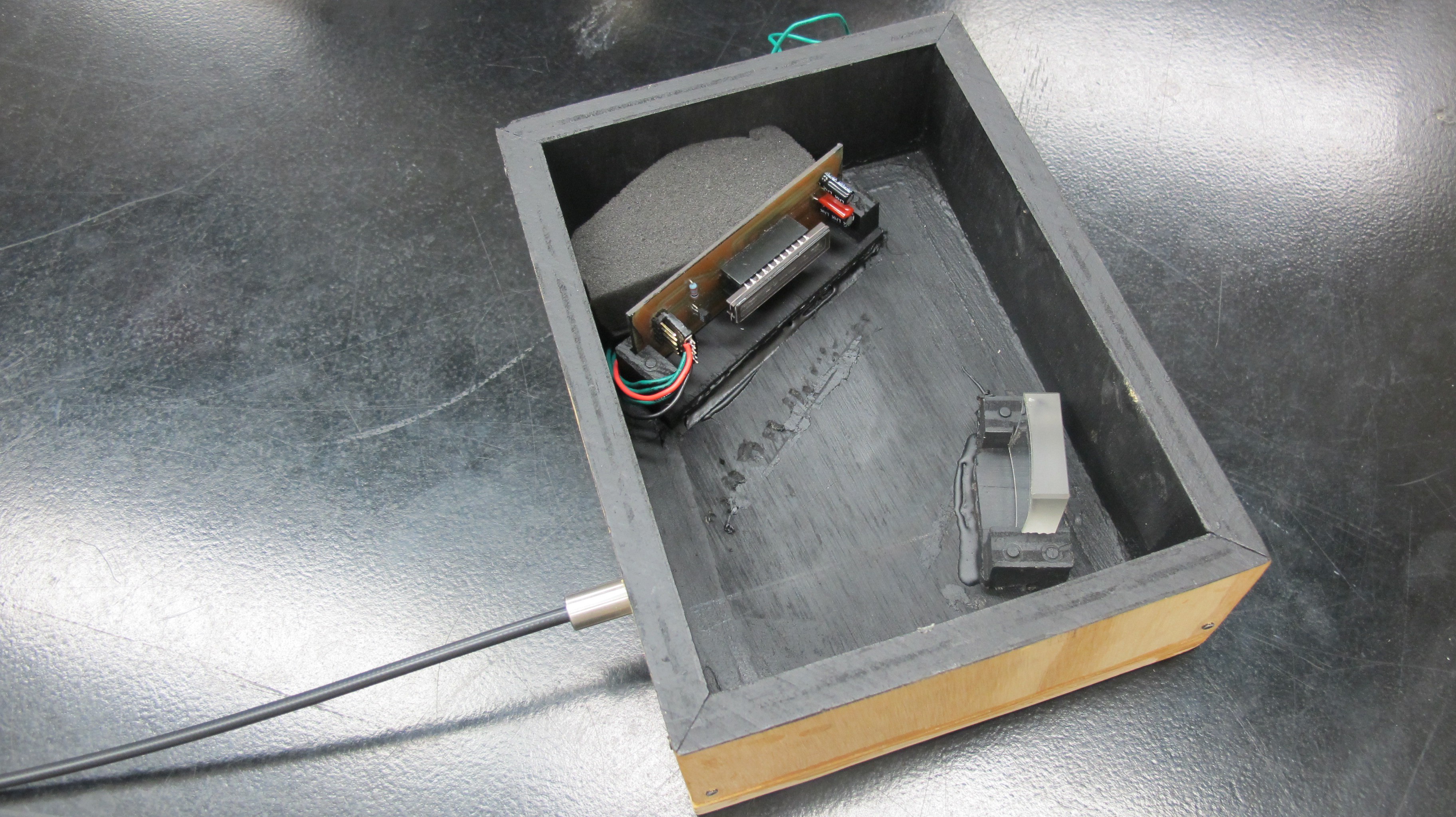
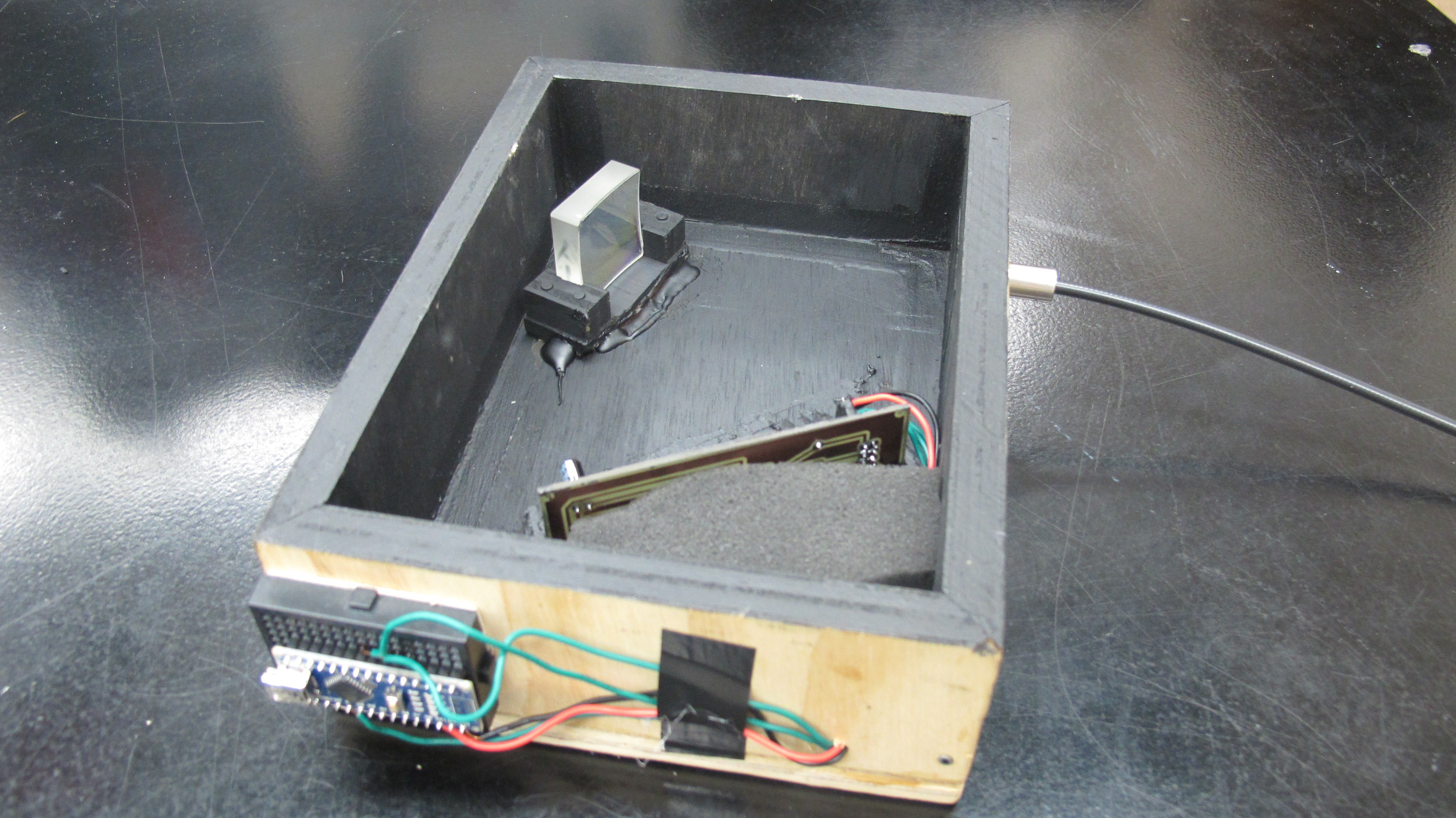
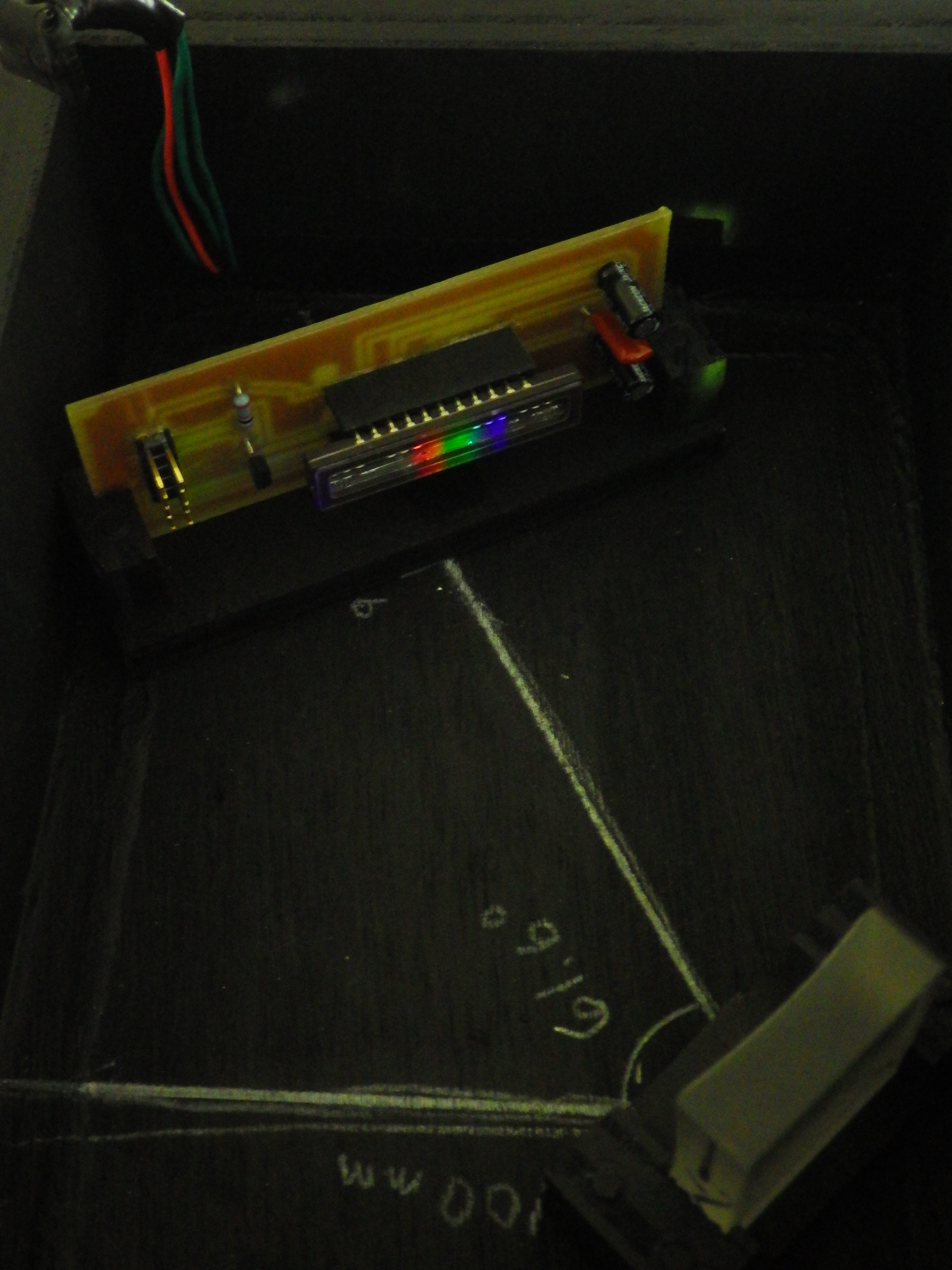
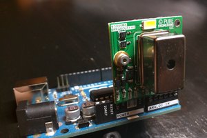
The current version of the spectrometer is contained within a wooden box but here are the core components.
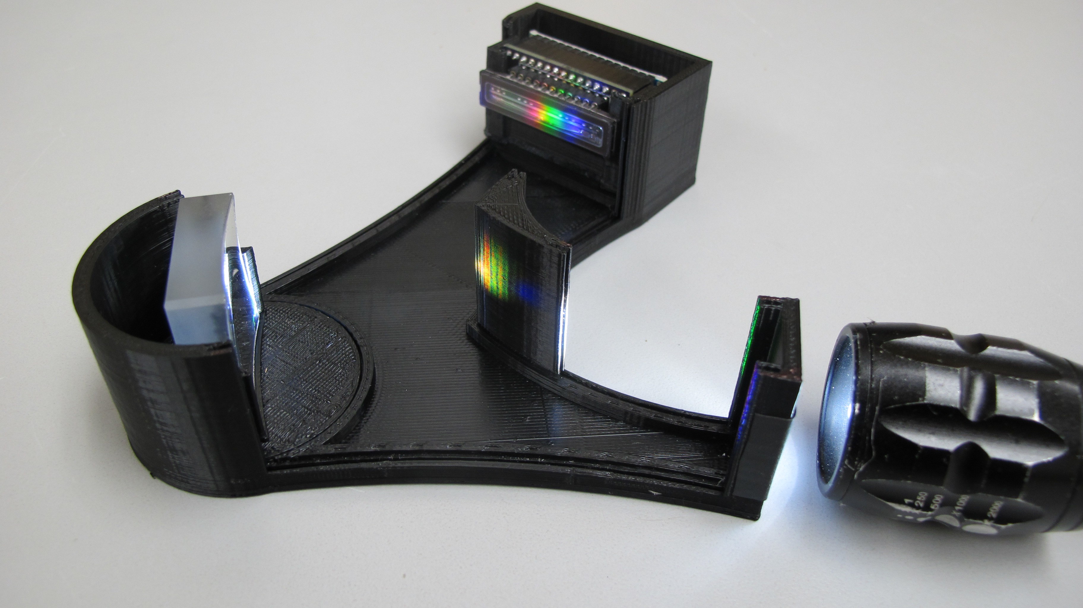
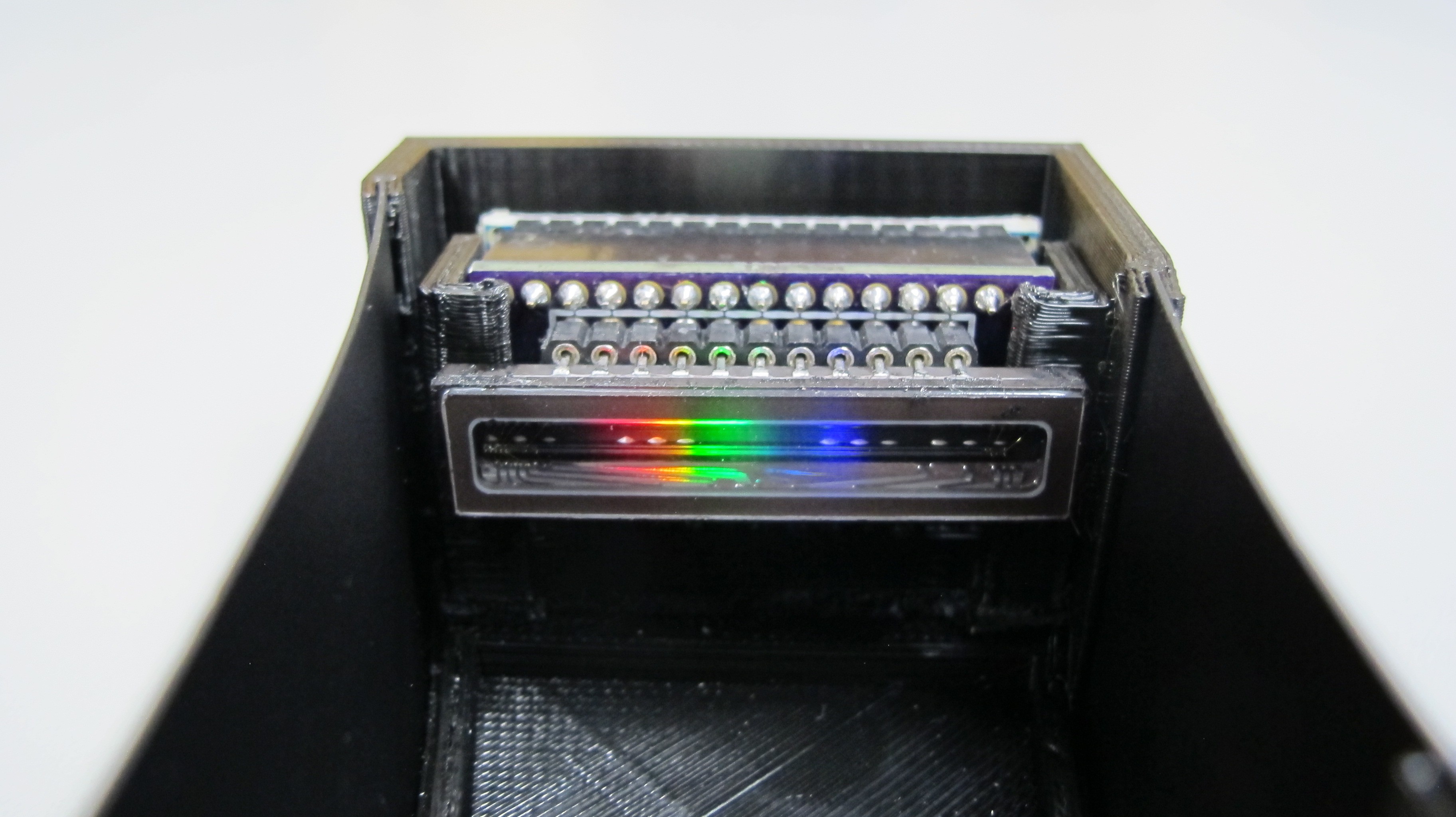
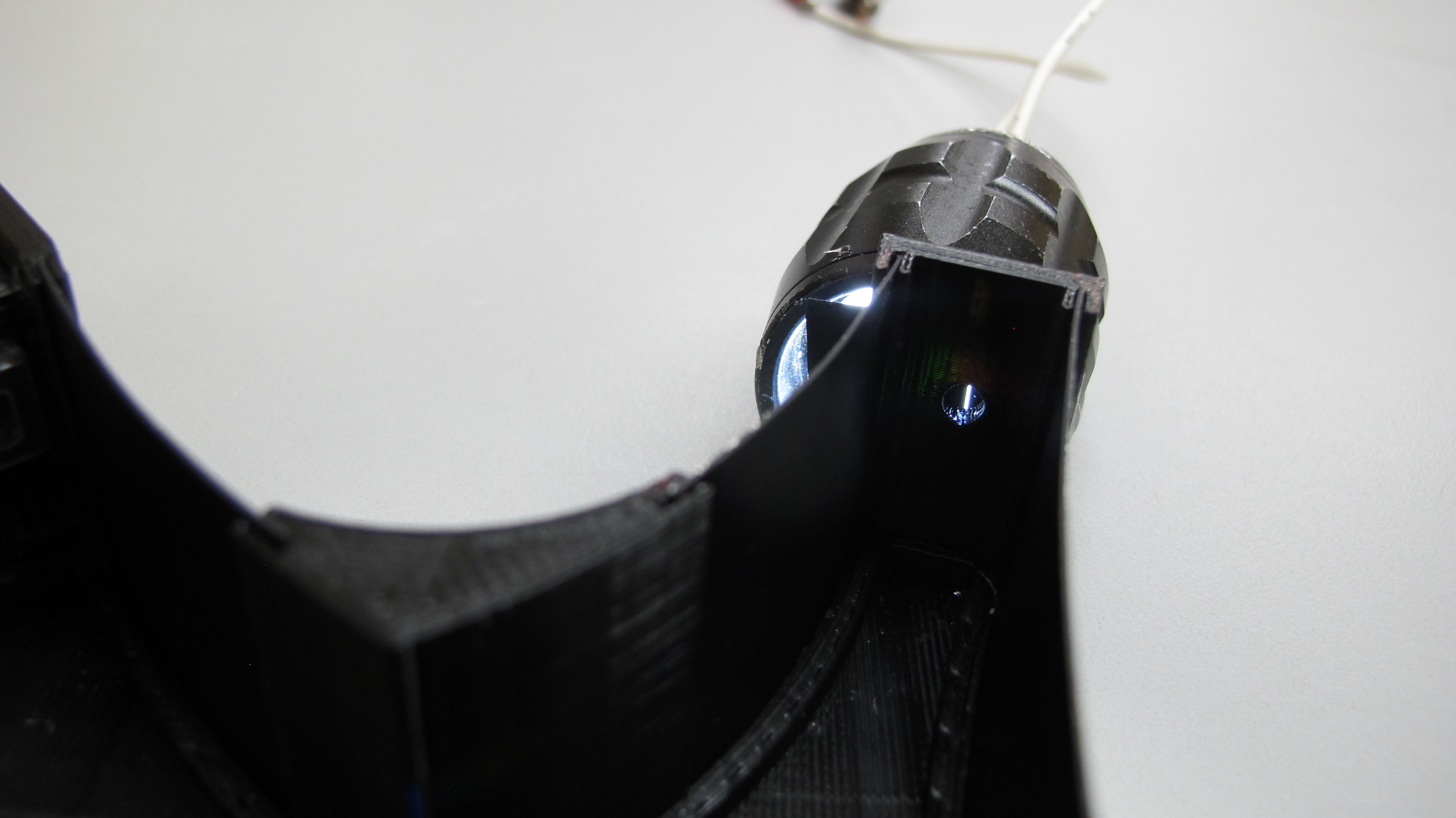
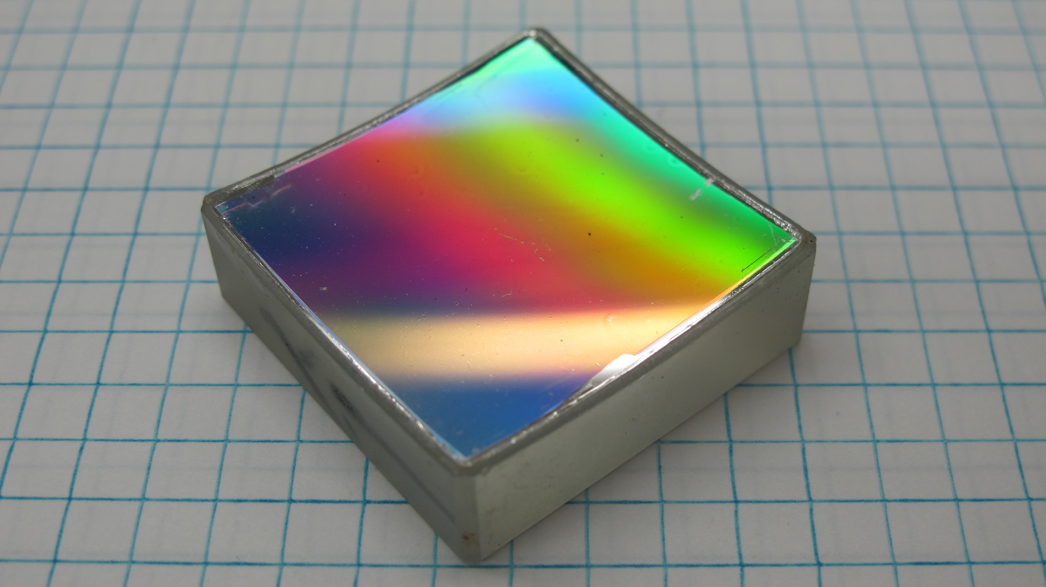
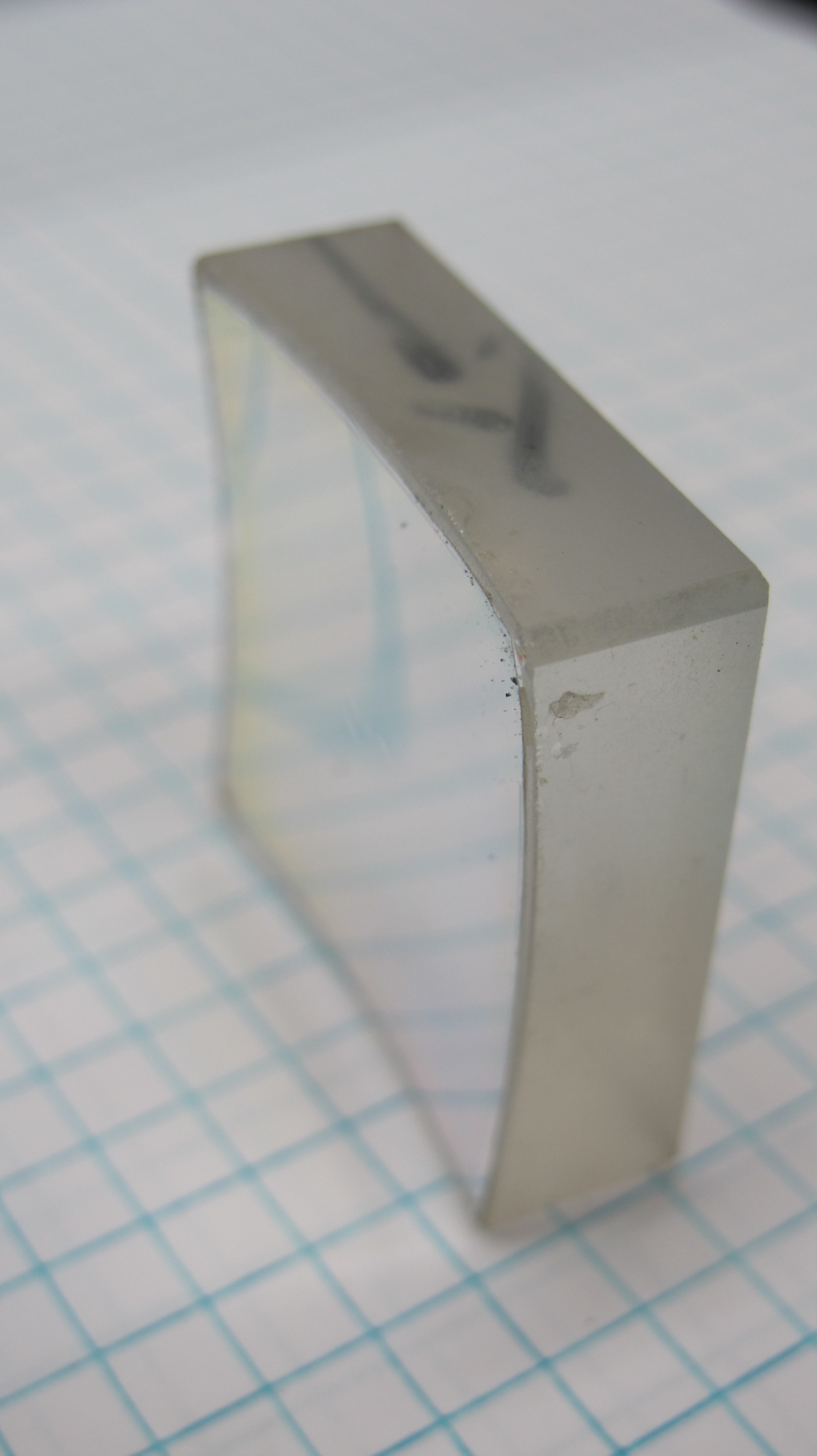
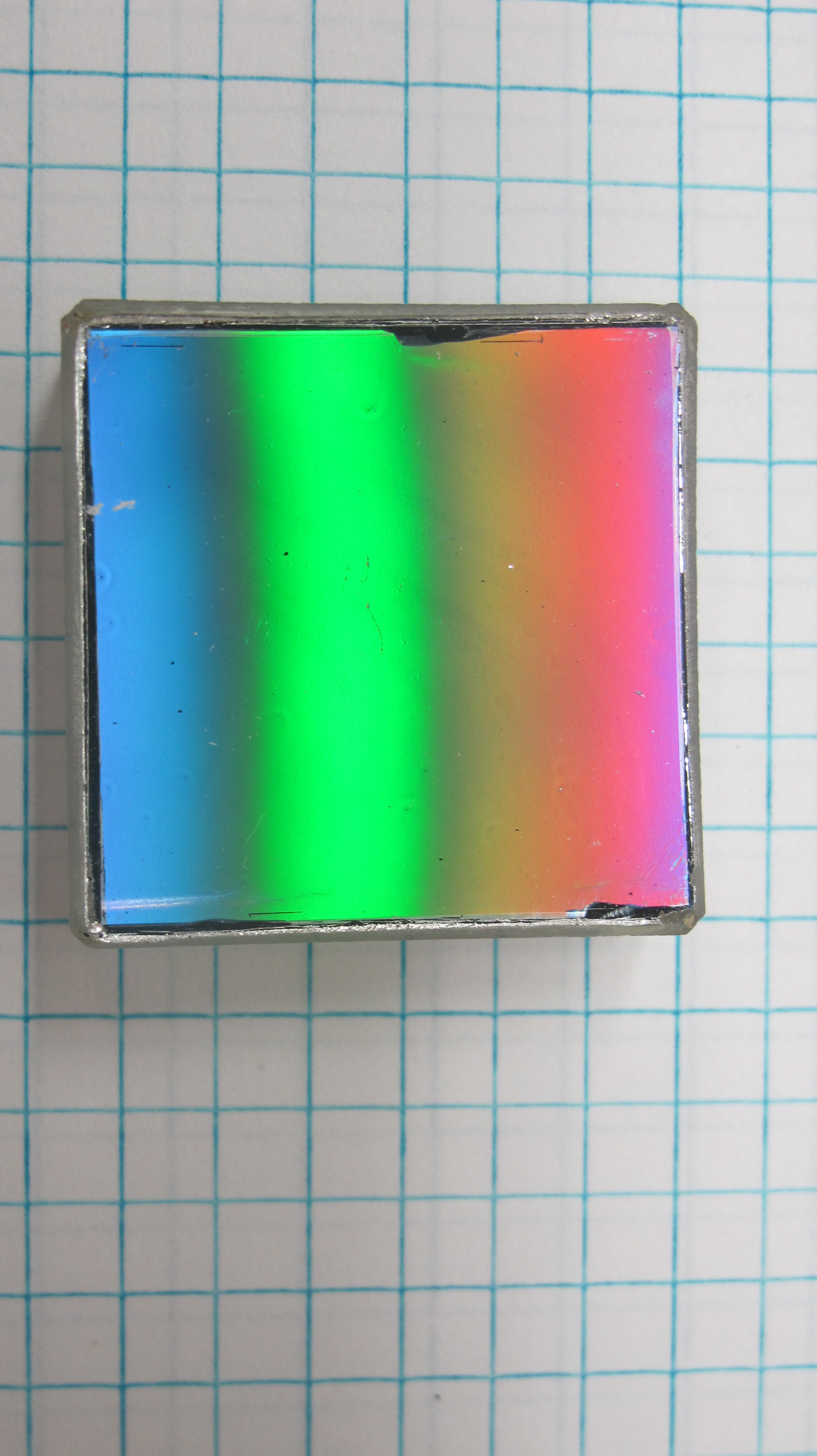
1. Concave holographic diffraction grating.
2. Printed acetate slit from Public Labs.
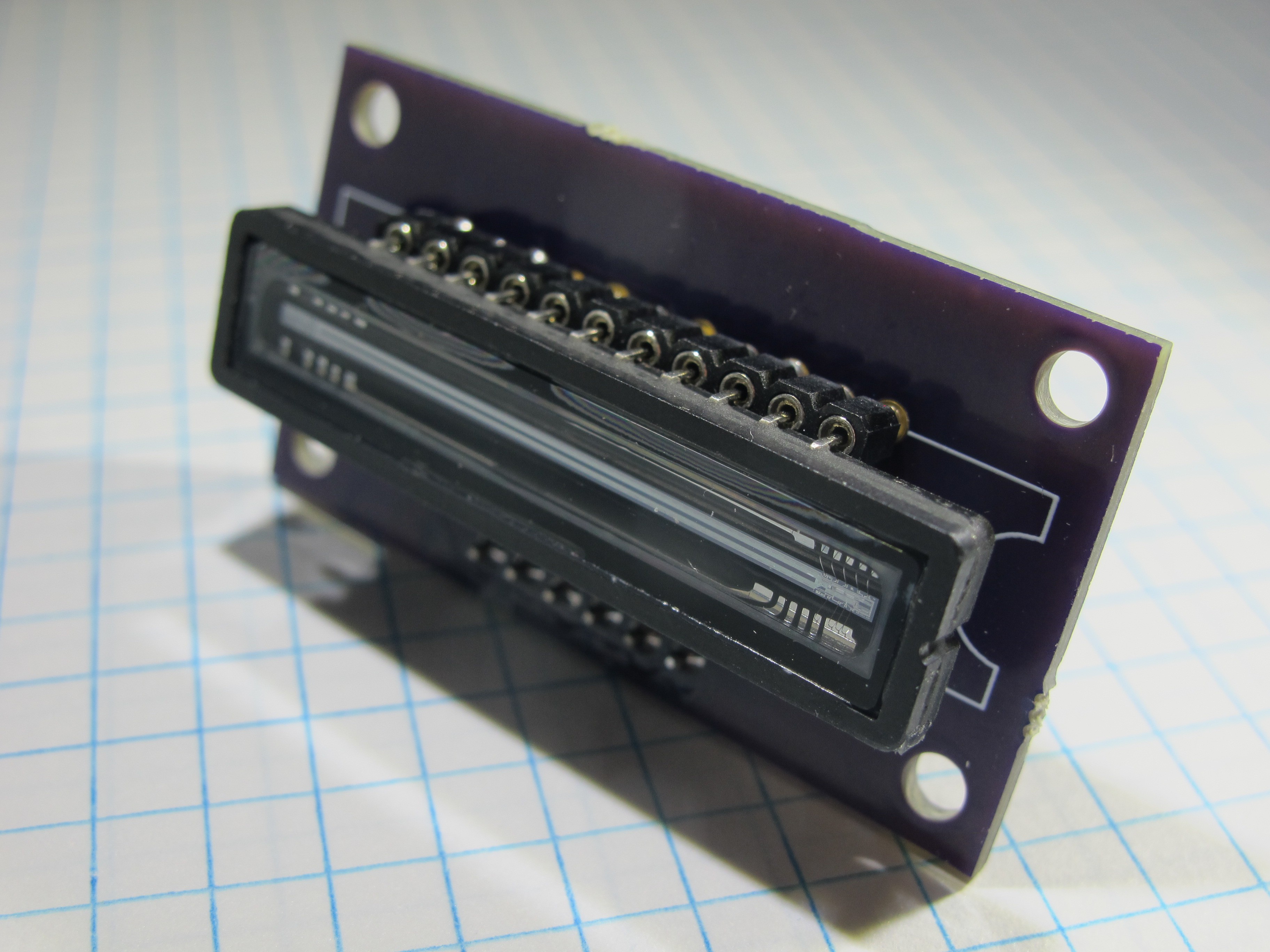
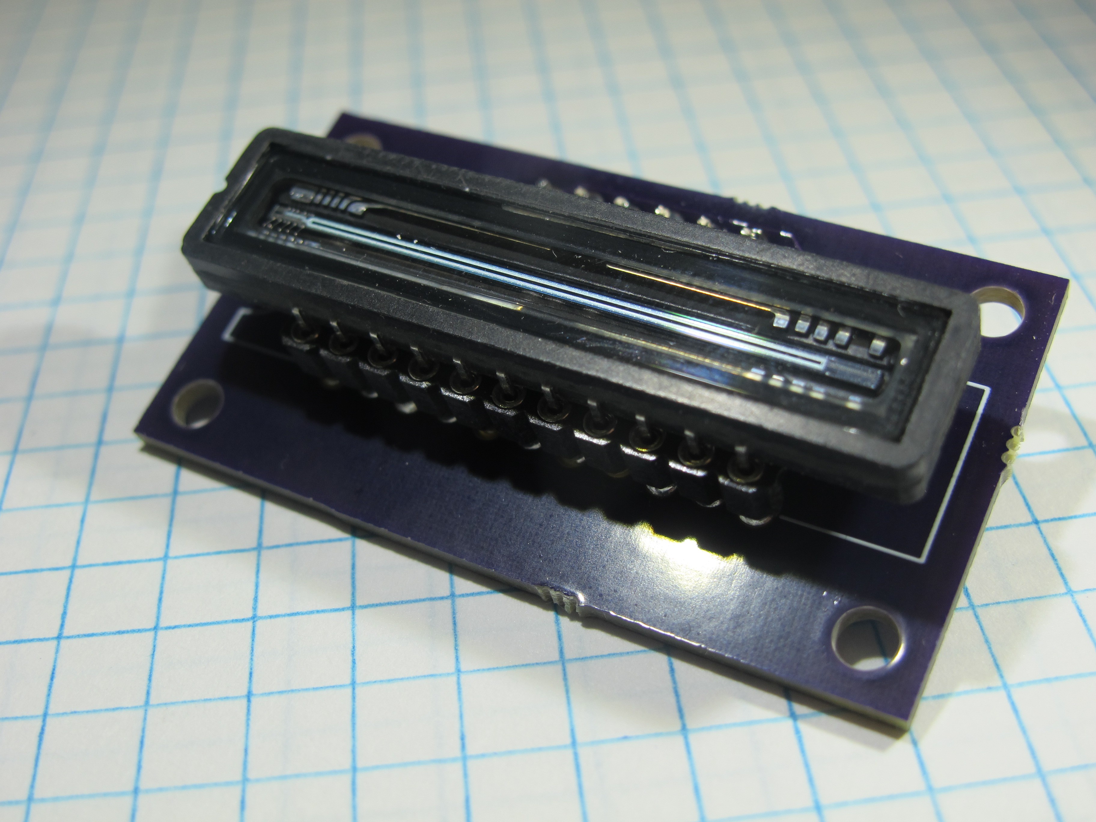
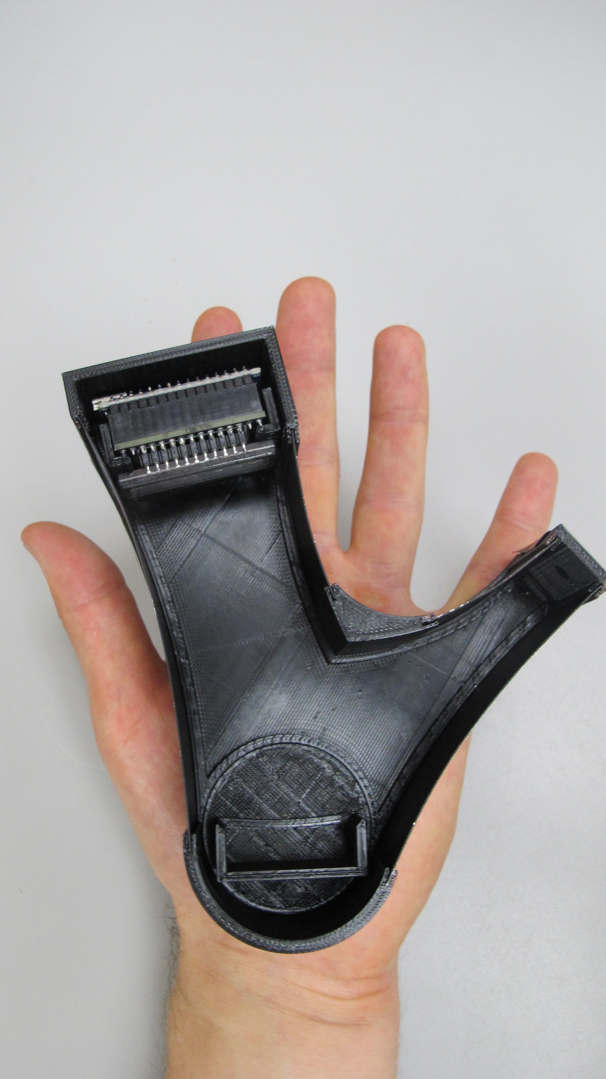
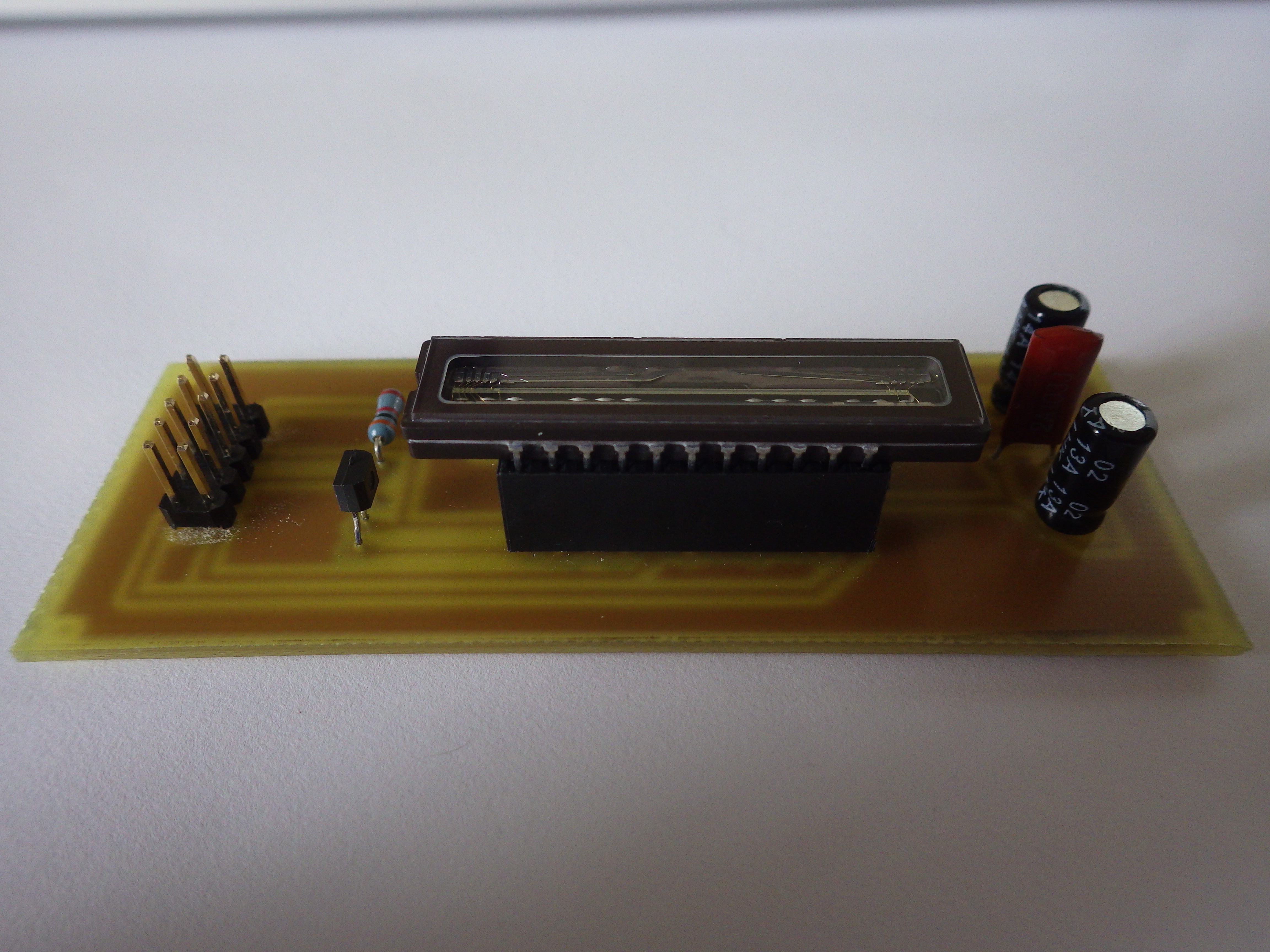
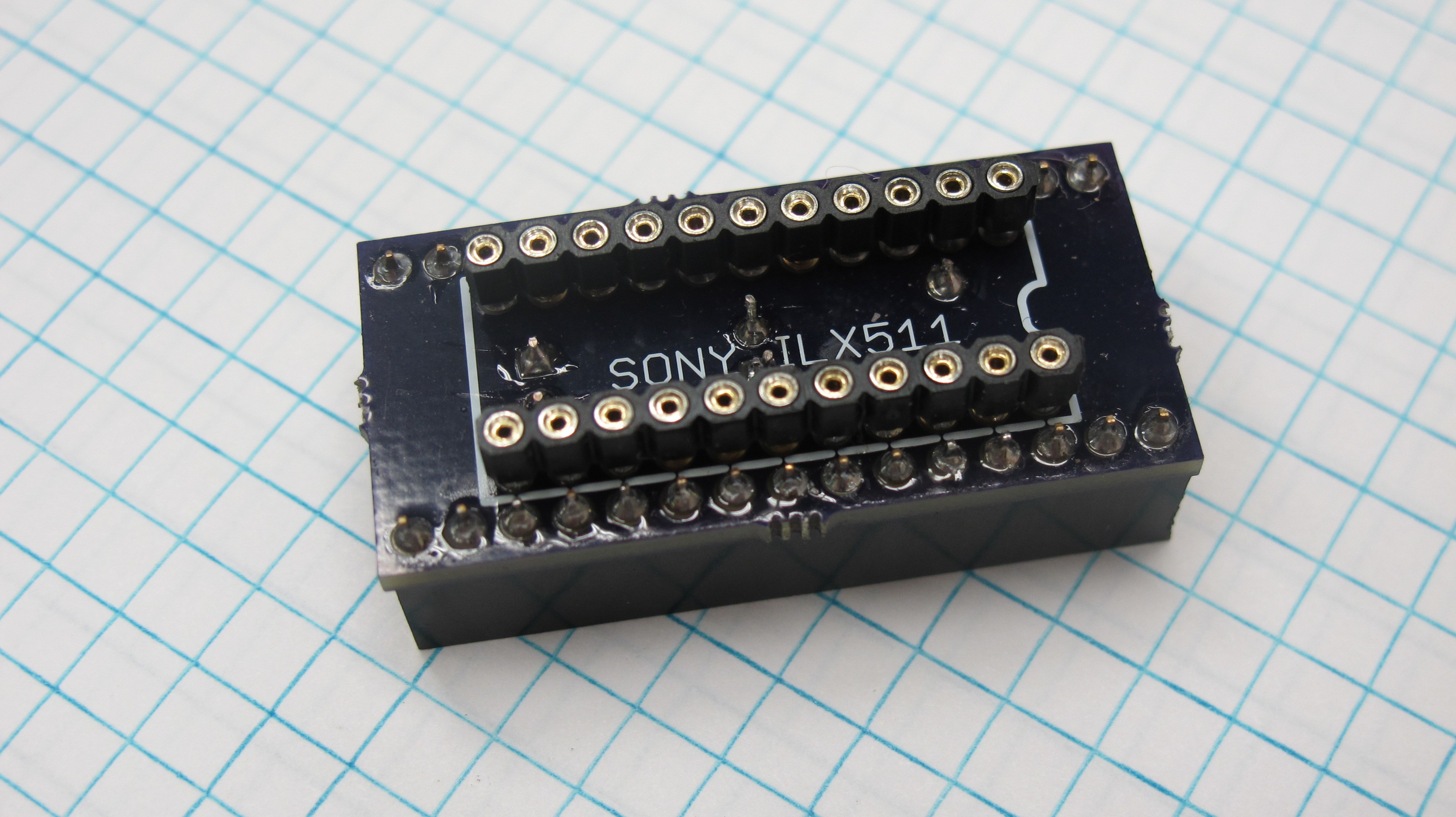
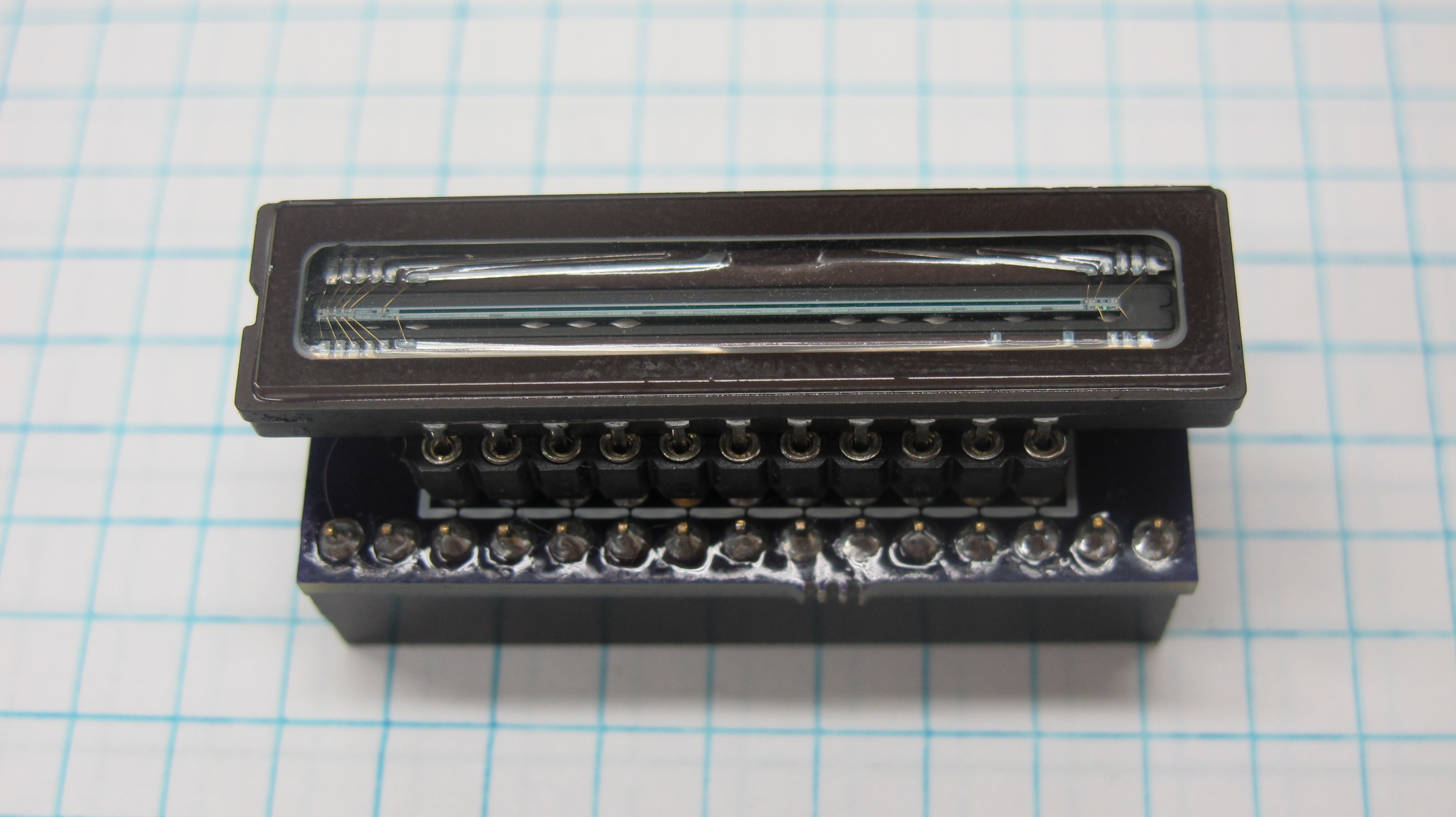
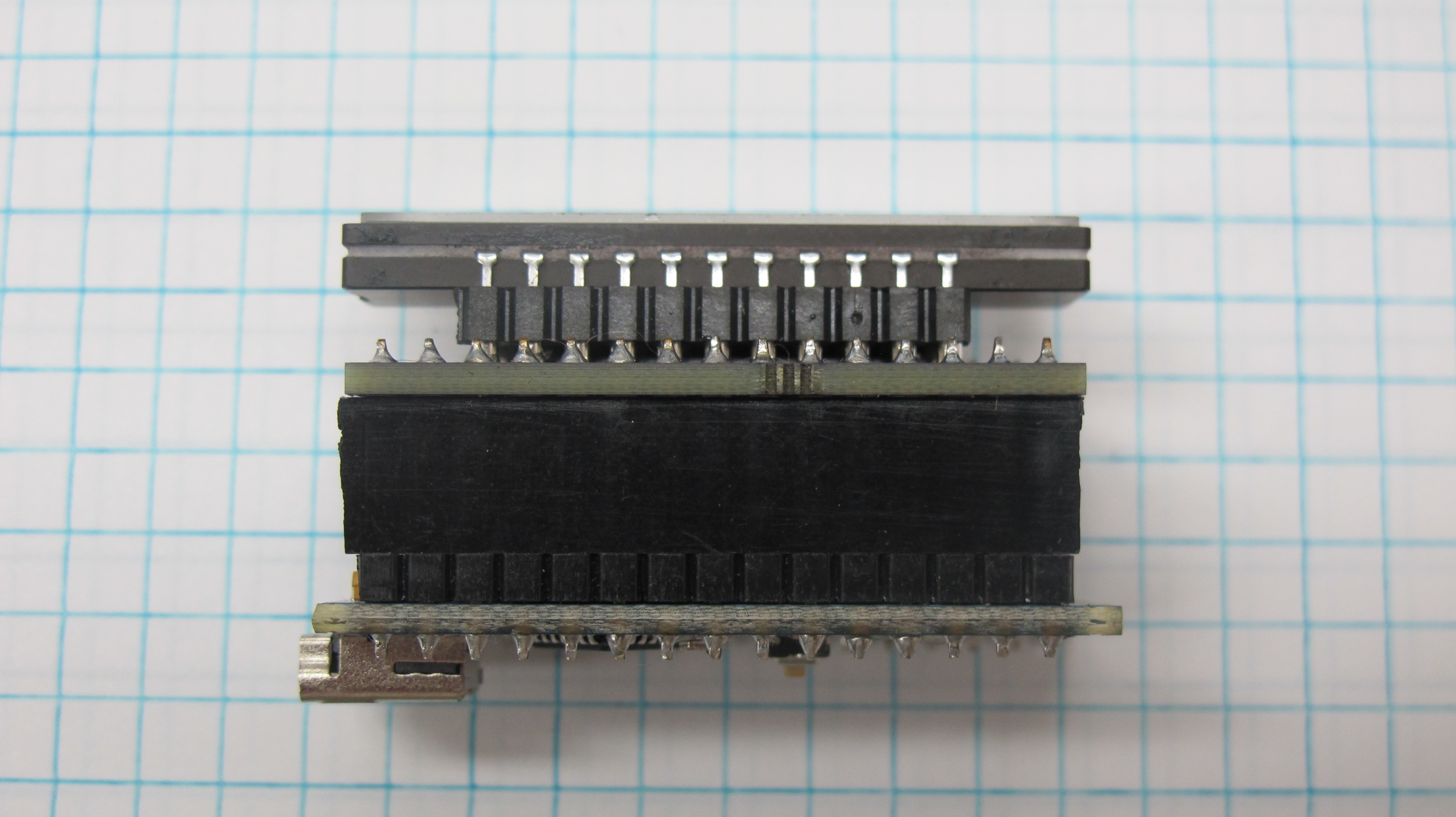
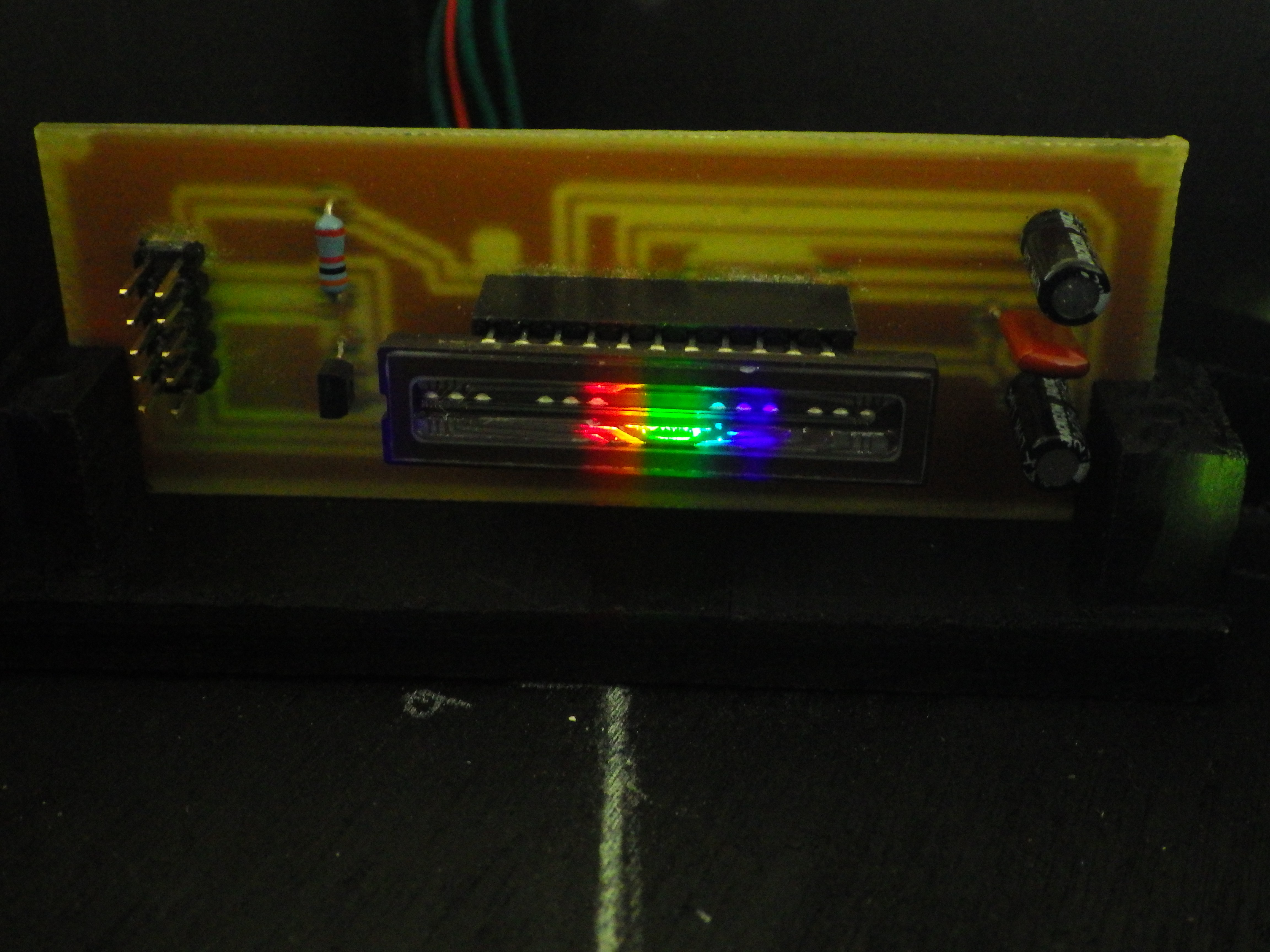
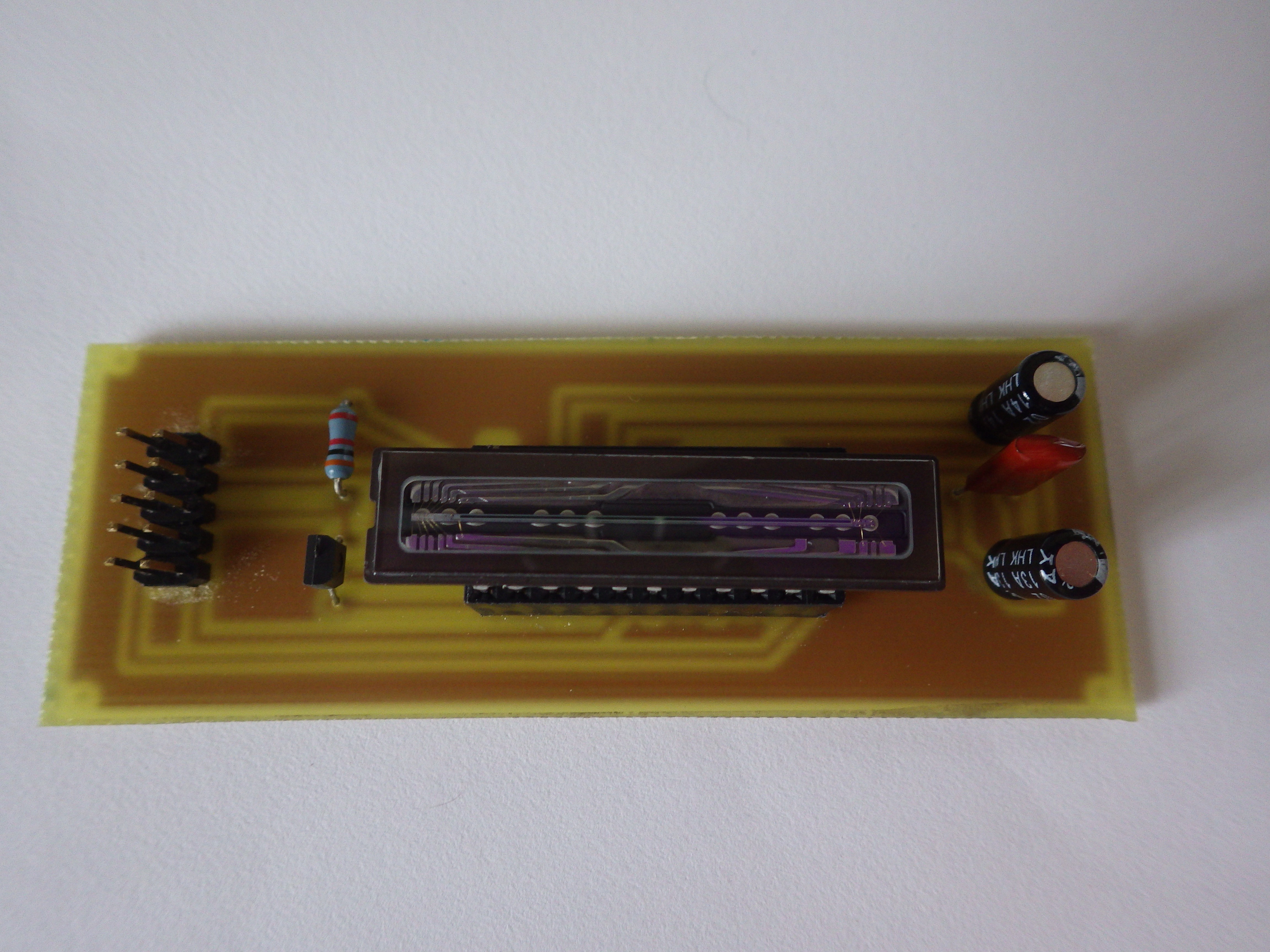
3. Sony ILX511B CCD
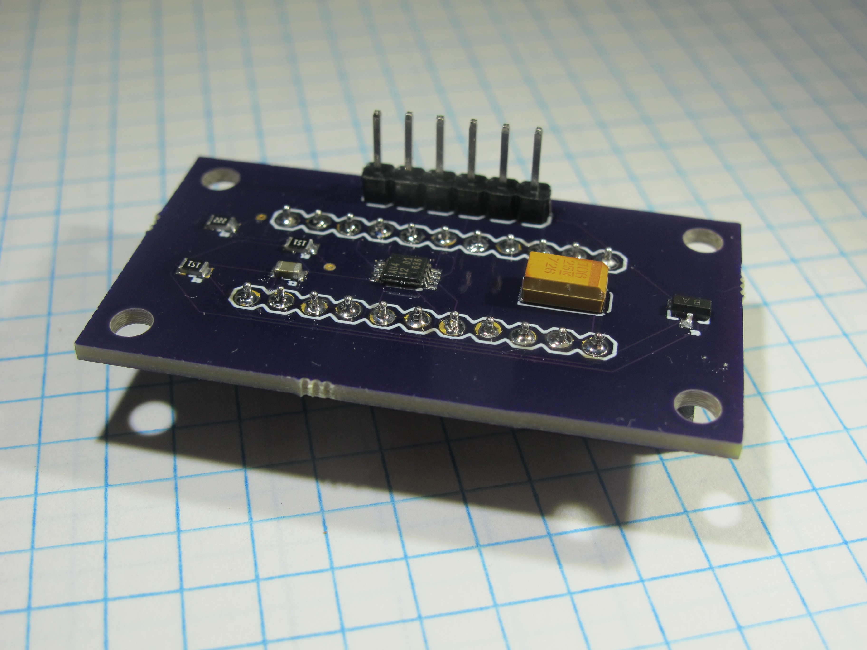
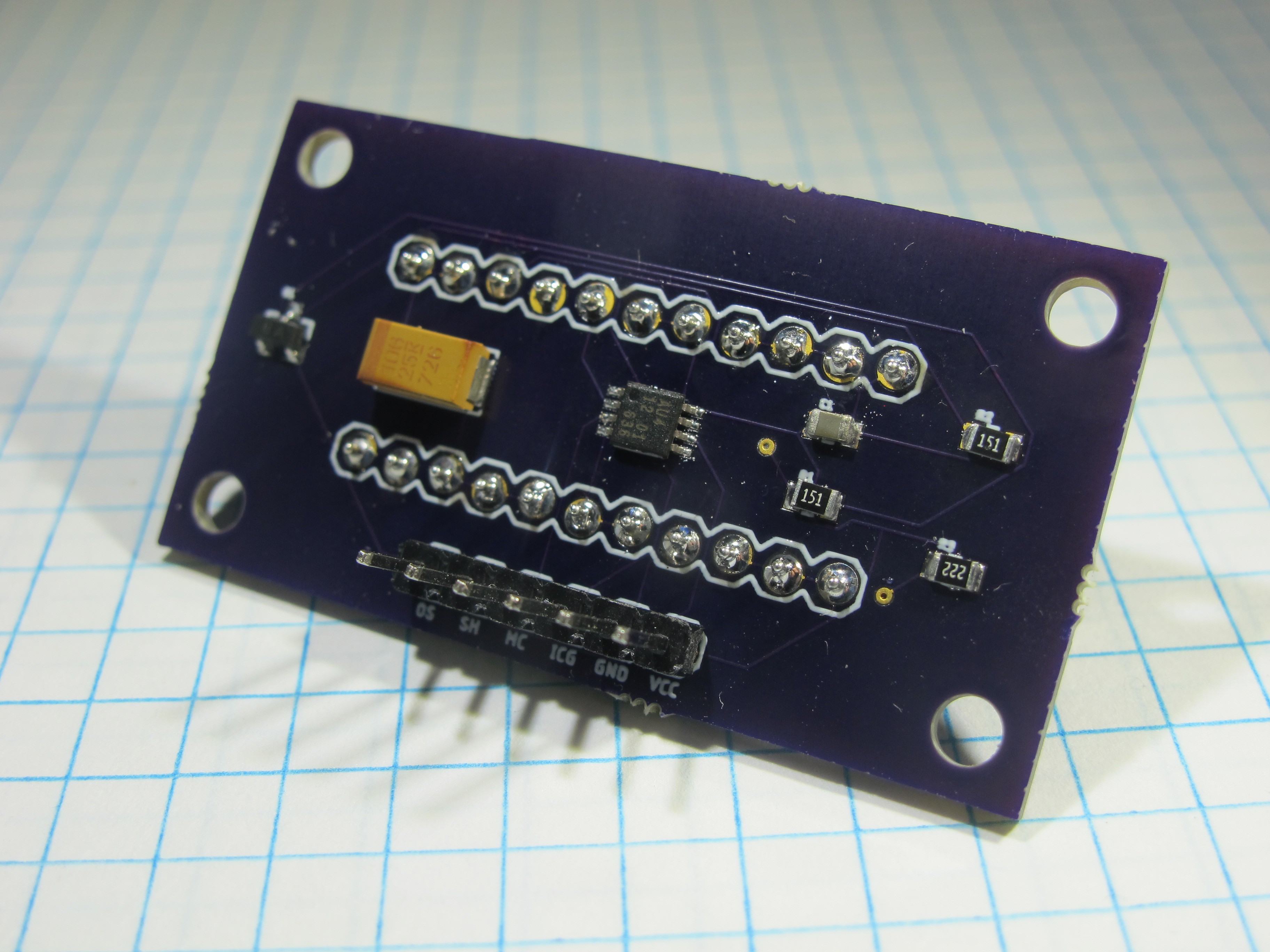
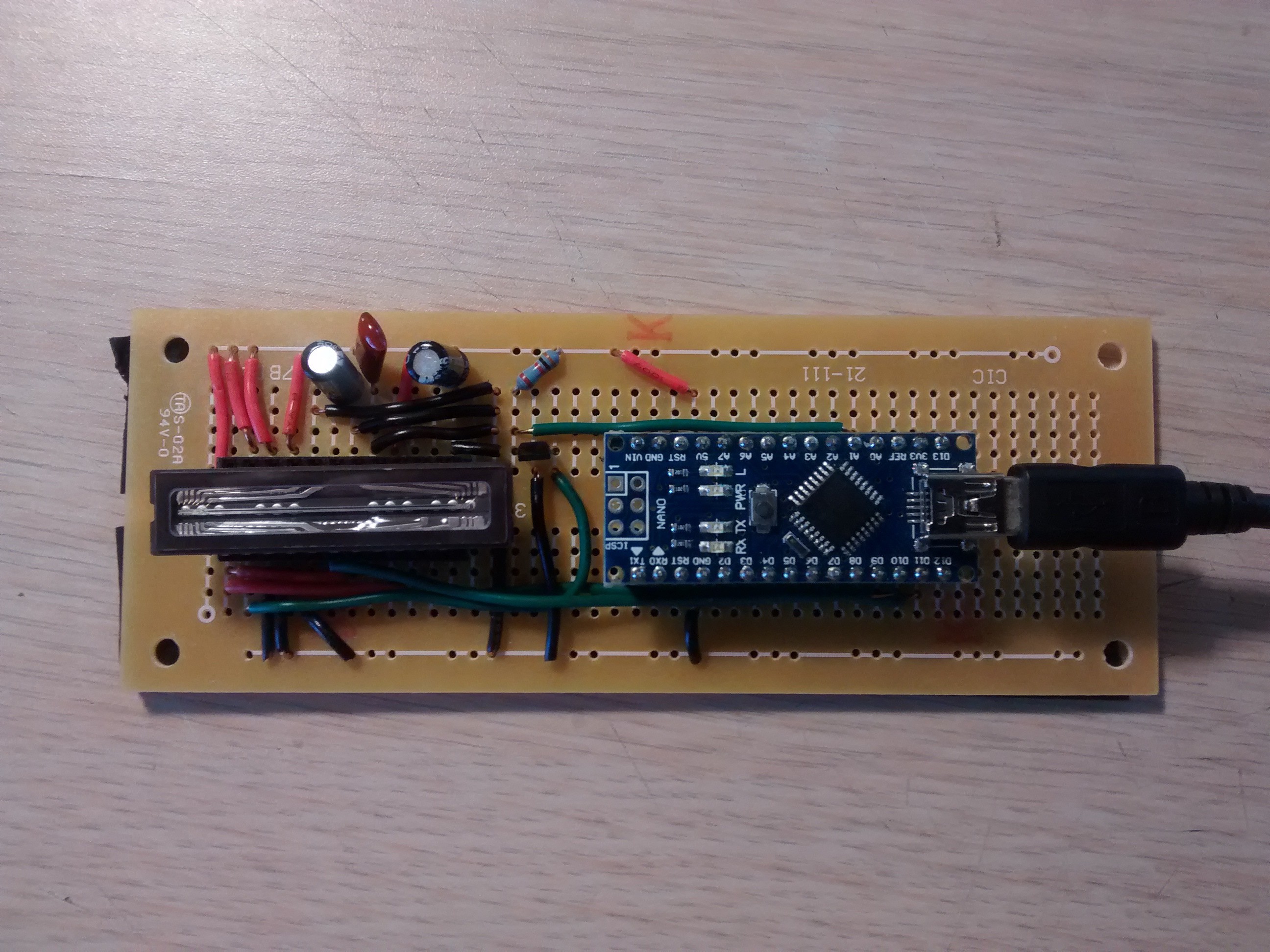
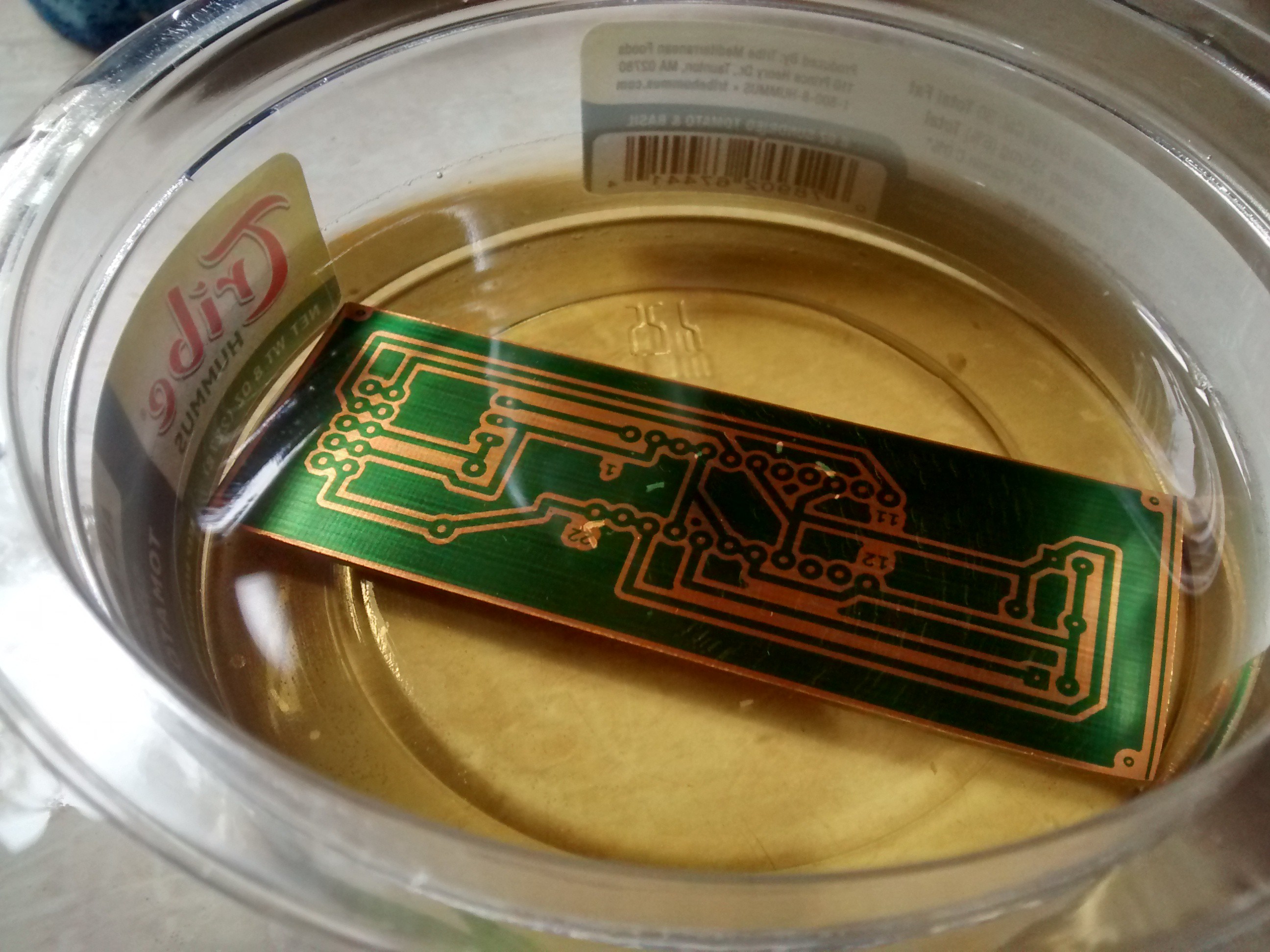
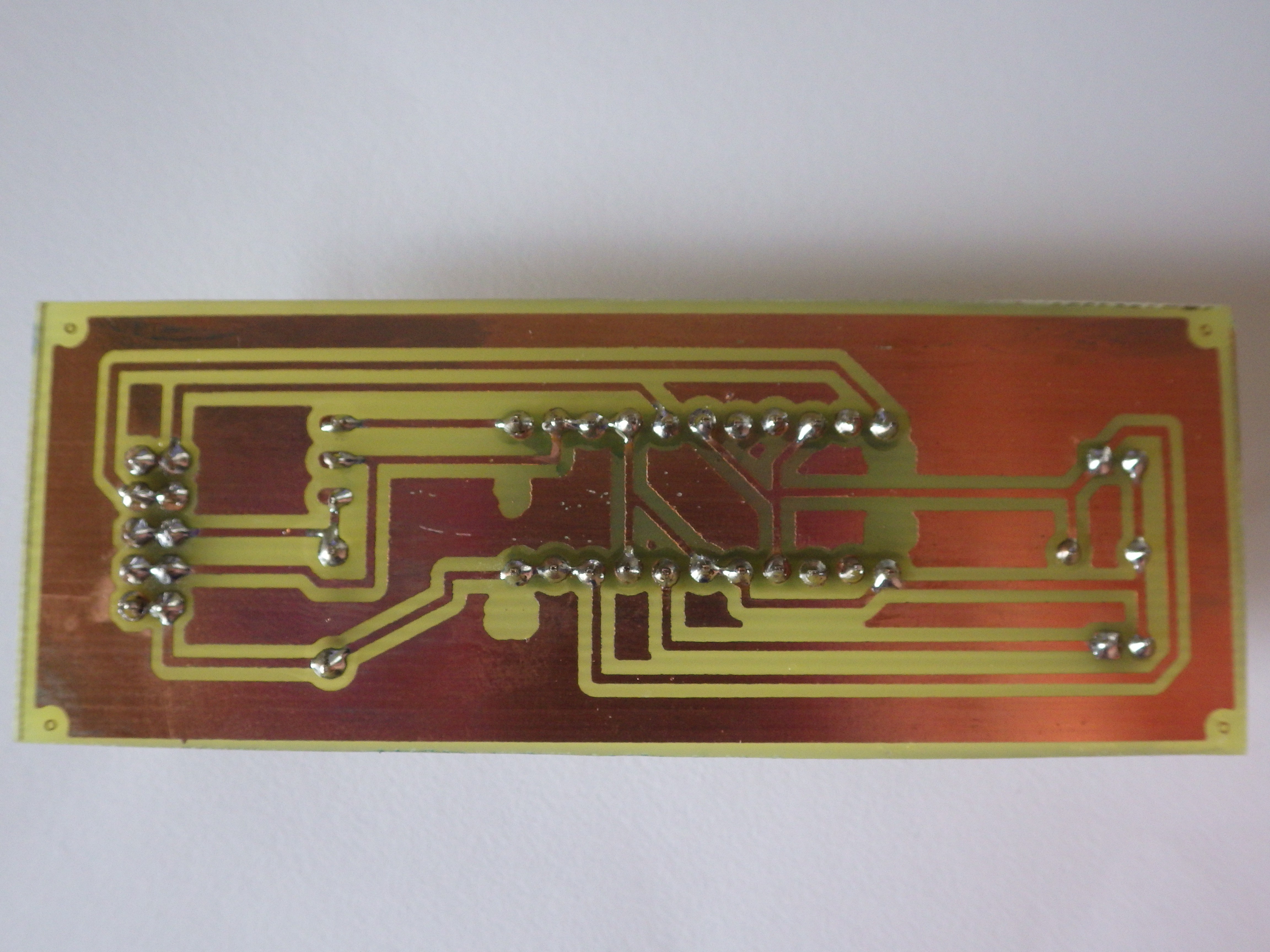
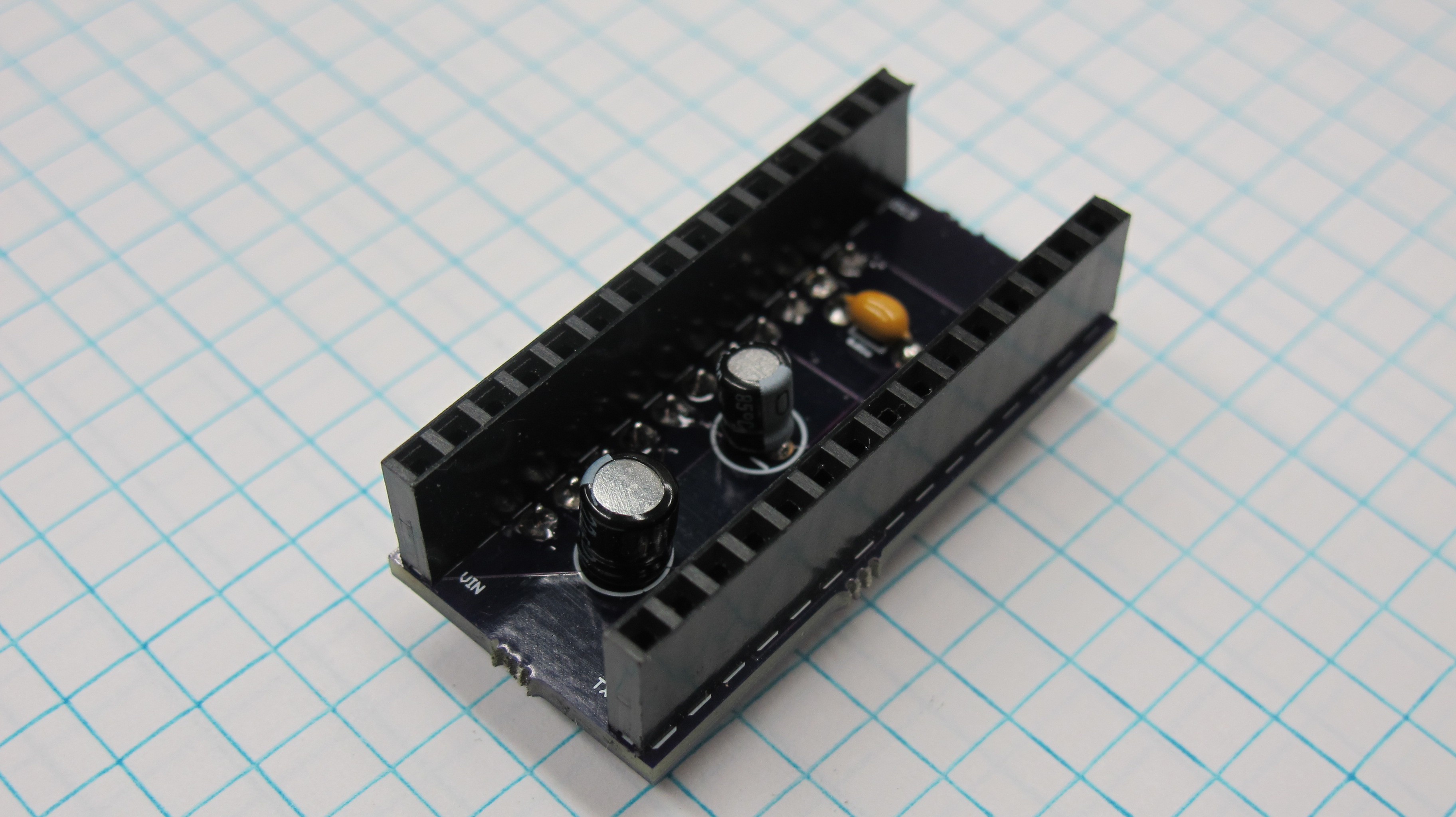
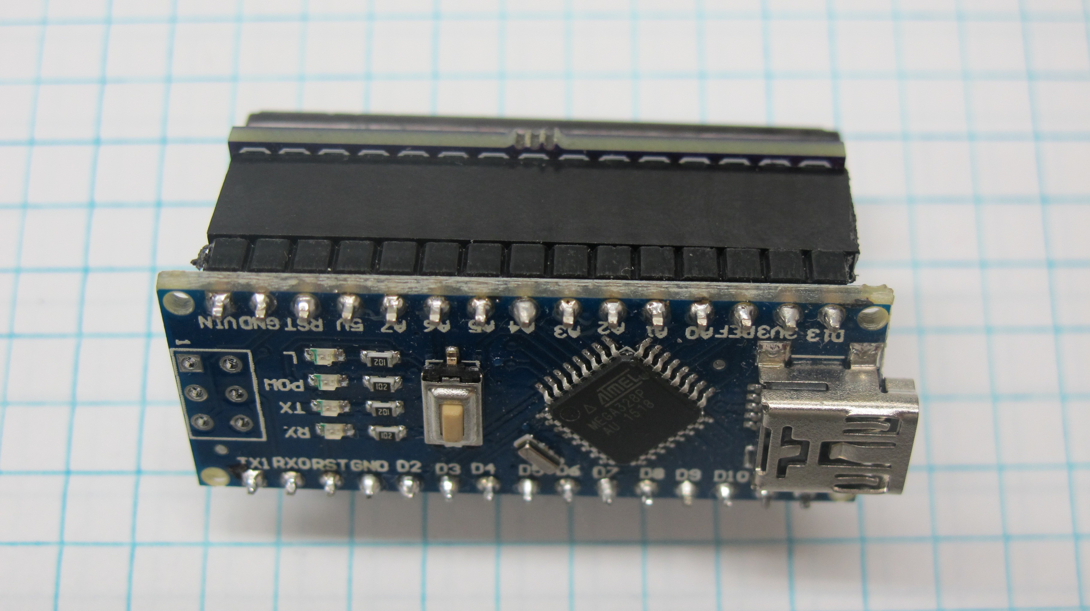
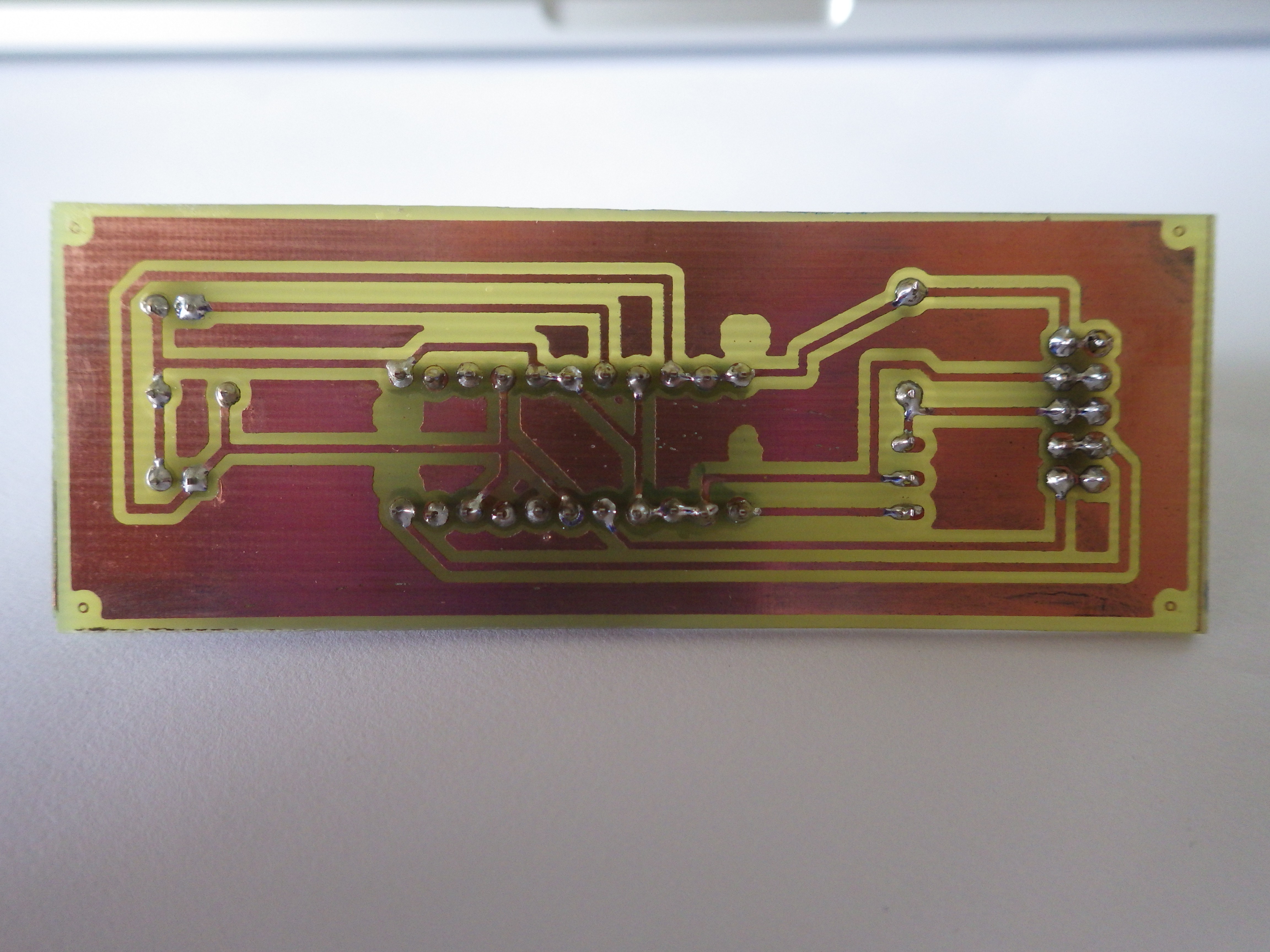
4. Custom made circuit controlled by an Arduino Nano to operate the CCD and transmit data to a computer for display.
There is ALOT more to be added about the project in its current state and future progress but for the time being I am investing most of the free time I have to another project, PULSE: Profiler Underwater Light SEnsor., for the Hackaday 2016 prize.
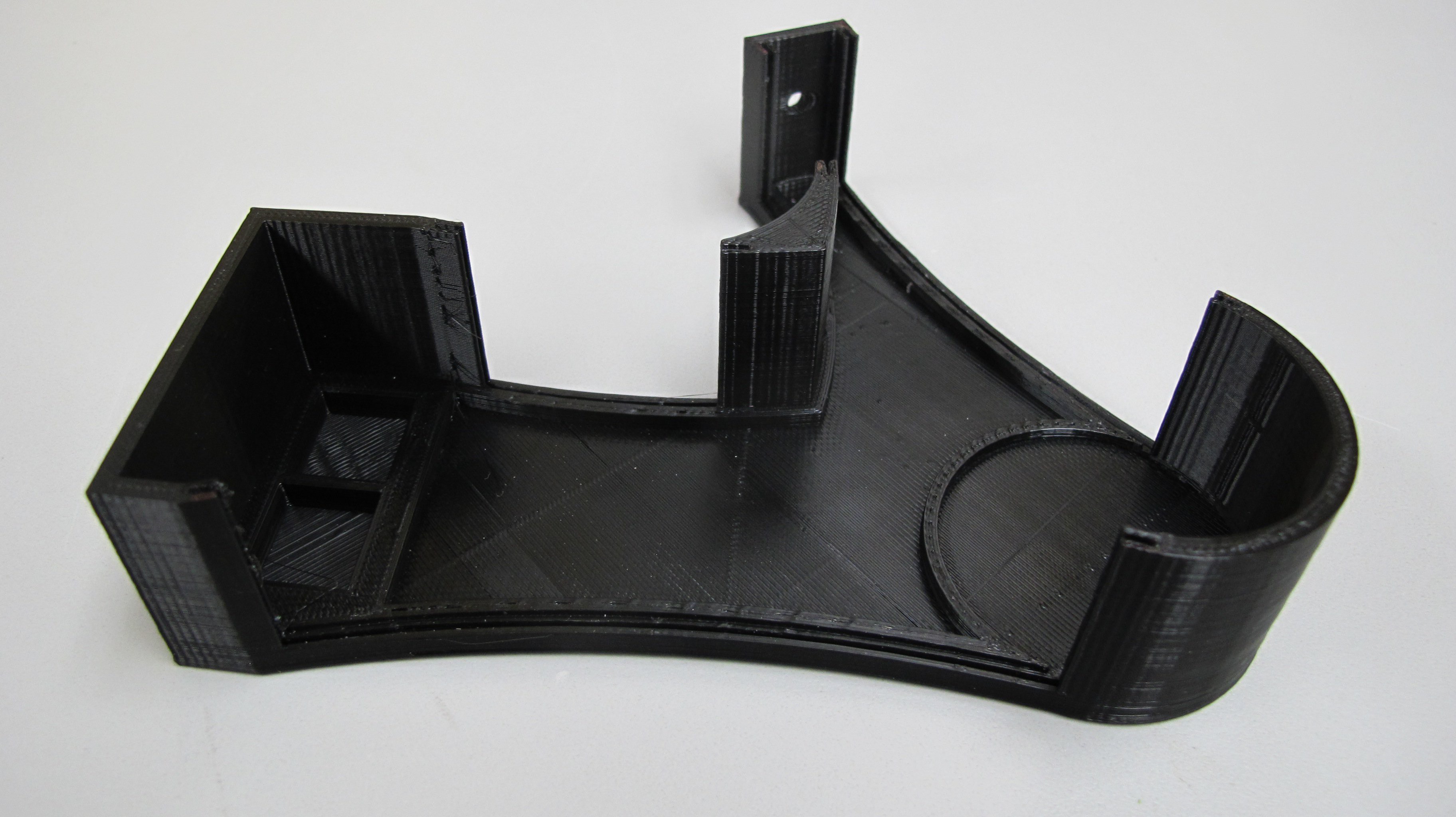
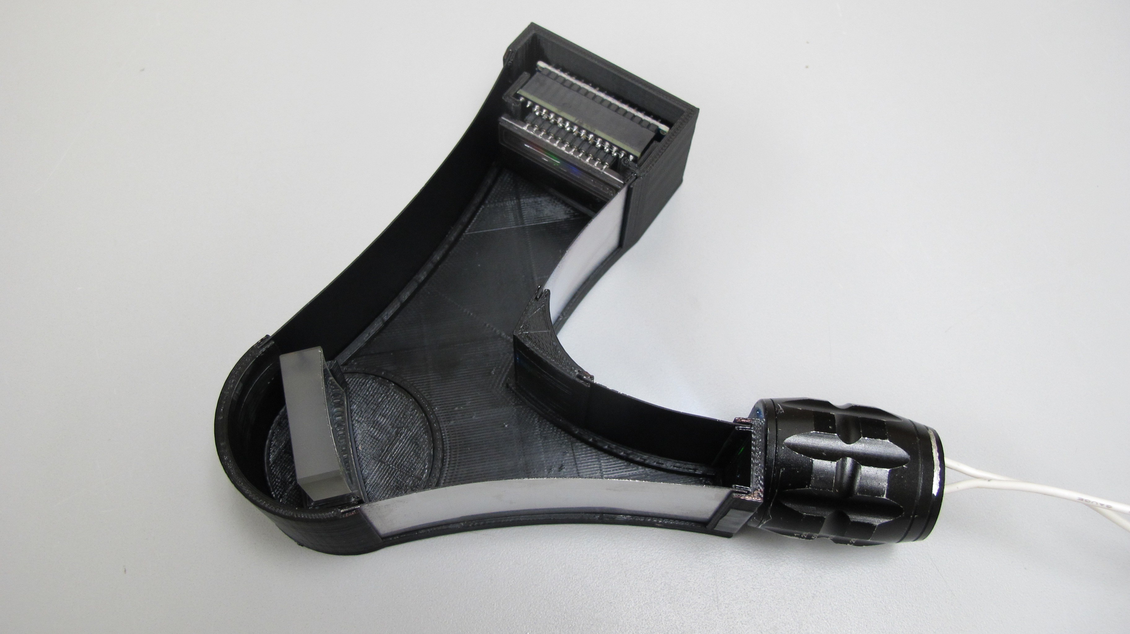
 Next up I need to design a cover and drill a hole to allow for USB connection to the CCD controller.
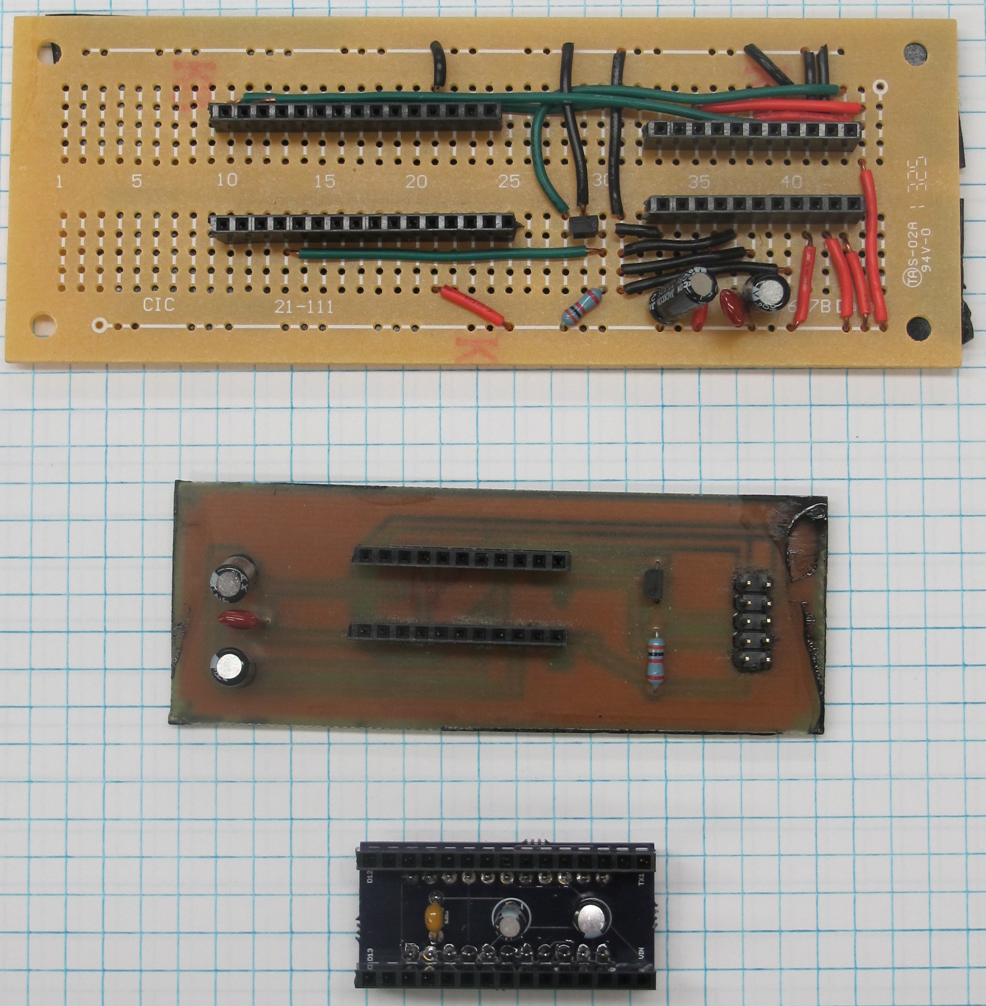

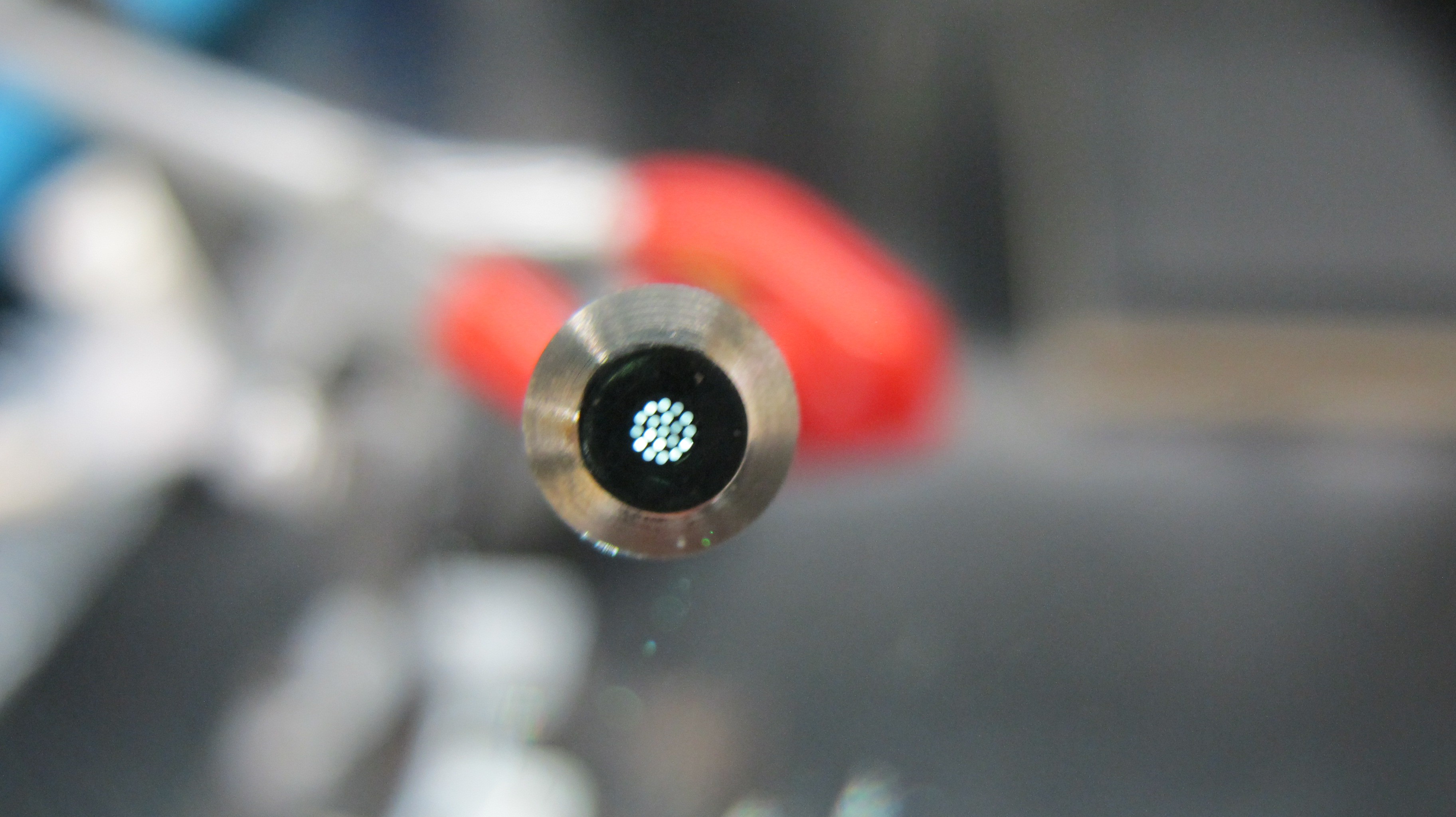
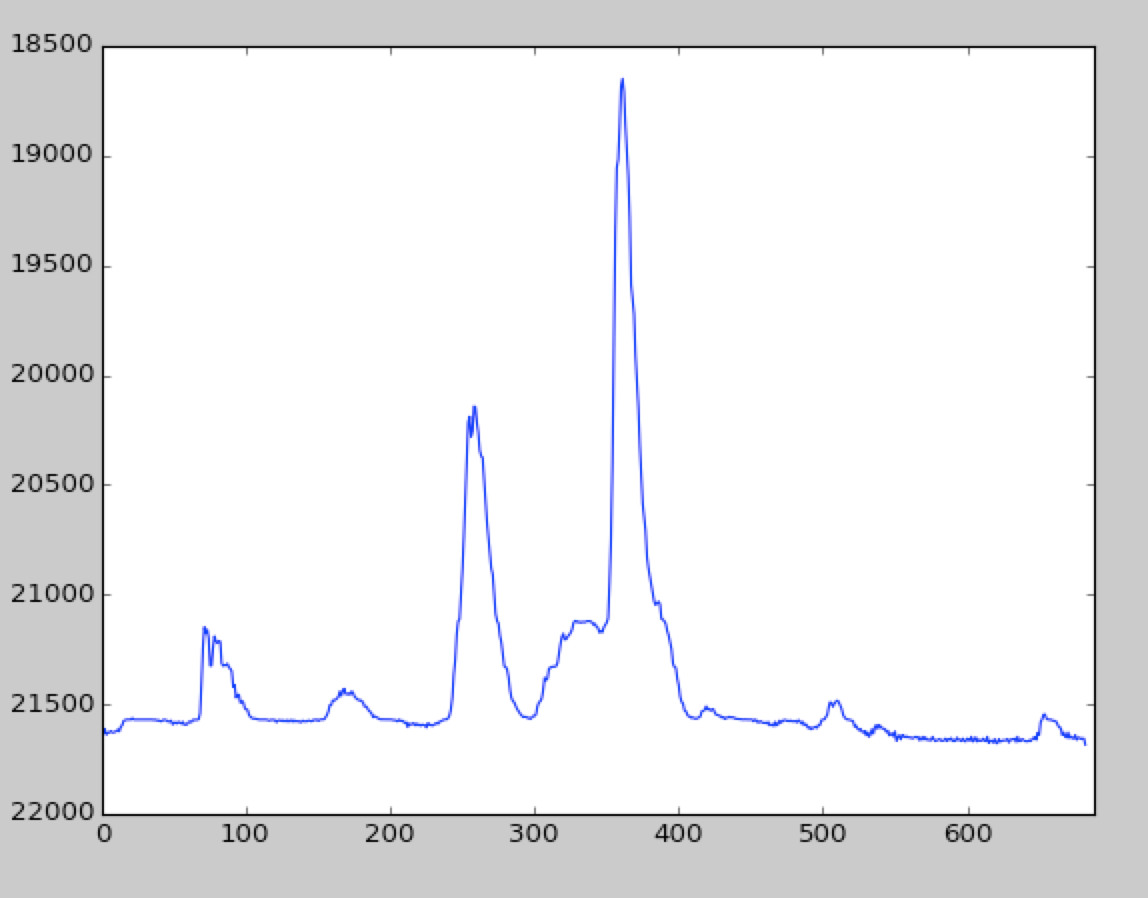
 Rectangular bundle


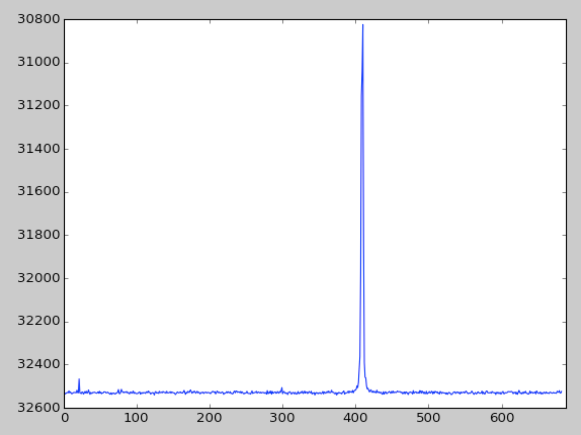
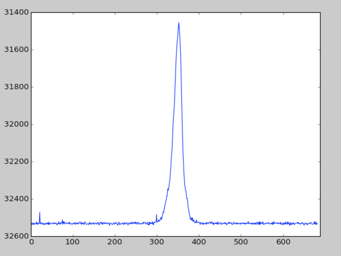
 CFL Bulb


 Pure Engineering
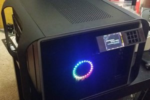
 fl@C@
fl@C@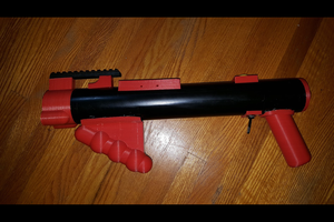
 Brian McEvoy
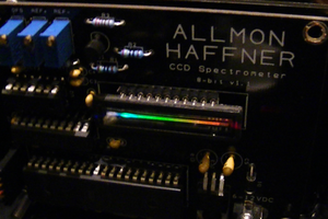
 David H Haffner Sr
Did you abandon the ILX511B because the other CCD (TCD1304) because it has built in logic controller to simplify the overall design? Would have been interesting to see the usage of the ILX511B which could controlled for other functions.