 Kevin Osuna
The components for this project are following:x1 NeoGeo Pocket.
- x1 NeoGeo Pocket
![]()
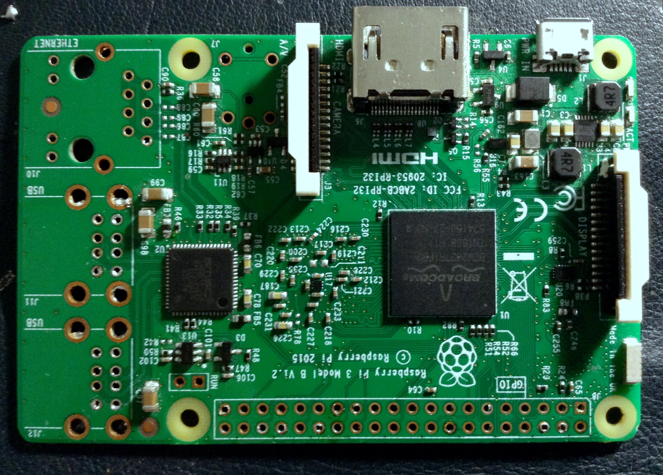
- x1 Raspberry Pi 3 or Rpi2 (less power consumption but less performance).
![]()


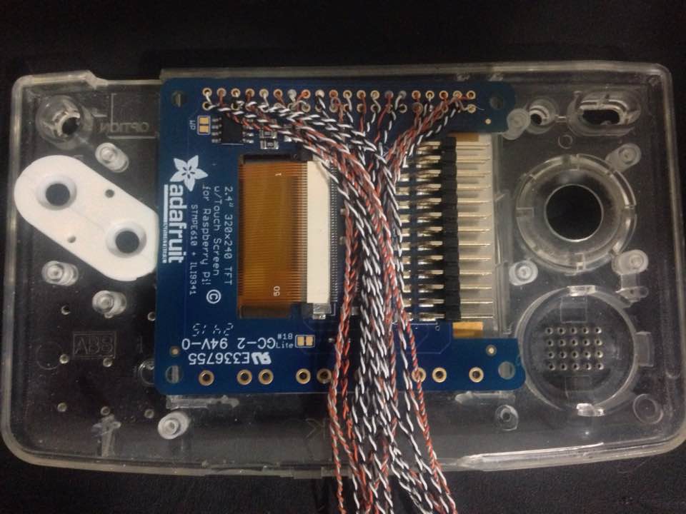
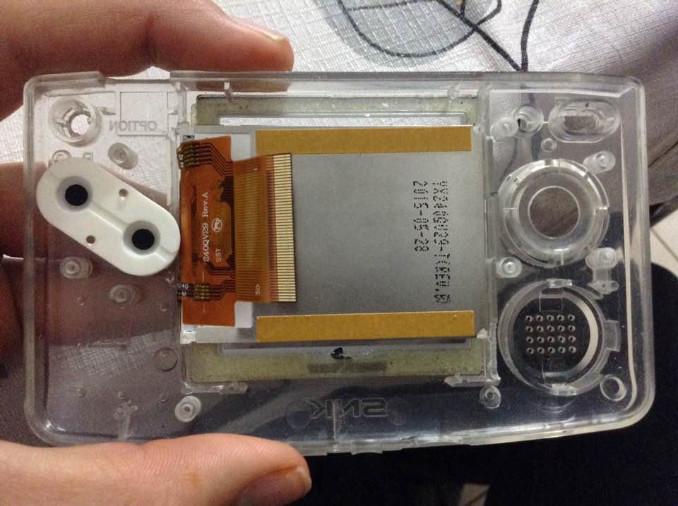
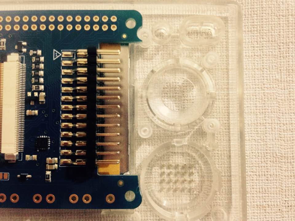
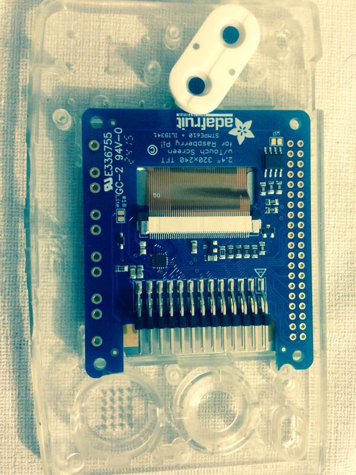
- x1 2.4 PiTFT from adafruit
![]()

- x1 Teensy 3.2.
![]()

- x1 blackberry trackball breakout board from SparkFun or Icstation (which is a lot more affordable and has almost no difference. I'll explain this later).
![]()
![]()


- x1 powerboost 1000c, there are other option that are better for the pi3 but sadly, I bought this without knowing at the time. I'll share the alternatives later.
![]()
- an stereo audio amp from Adafruit or a mono one. I got the mono since it was obviously cheaper; around 3 US dlls compared to 9dlls (I'm on a tight budget!)
![]()
- x10 Domed tactile switches by C&K components https://www.arrow.com/en/products/ksj0m21180shlft/ck-components
![]()


- x10 "Legendary" squared Tactile switches by Panasonic https://www.arrow.com/en/products/evq-p0d07k/panasonic
![]()

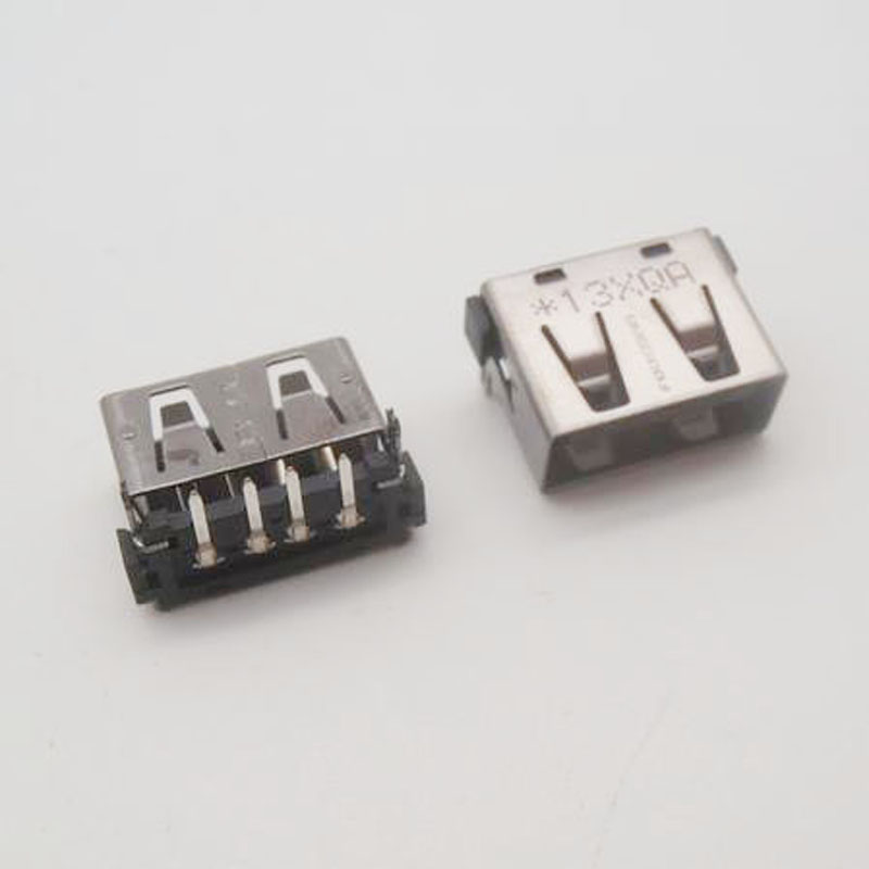
- x4 "short" USB ports, I got mine from an old and broken Toshiba Satellite A15 laptop. short ones are important because space is critical here!!!.
![]()
- x2 generic cellphone loud speakers (quite tiny as well but they output clear sound at a nice volume thanks to the amp).
![]()
- x2 cellphone vibrator motor (the smallest you can find)

- wires
![]()
- The hard part is to find the proper Li-Polymer battery, one that fits and has enough juice to power the device for 3-4 hours minimum. But we'll get to it :) I'll show some alternatives to properly power the Rpi3 specifically.

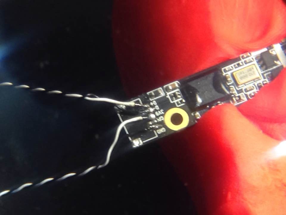
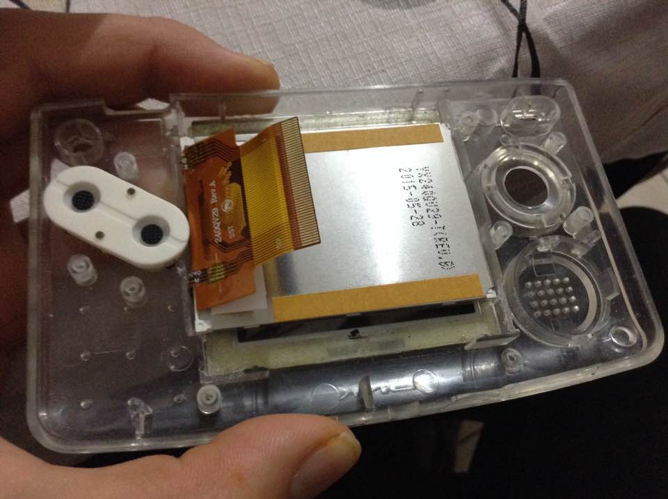
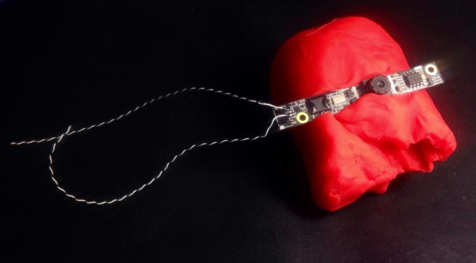 Then I carefully added some hot glue to secure the wires I had just soldered, at the end it looked very clean. After that, using the engraving tool, I made a hole through which the camera lense could go. I had to be very precise on how far I had to dig, I wanted it to be the perfectly sized and shaped. That way, there would be no need for glue on that part, after all, this is a very visible part but even if a had made a mistake, that can be covered with a custom, acrylic faceplate.
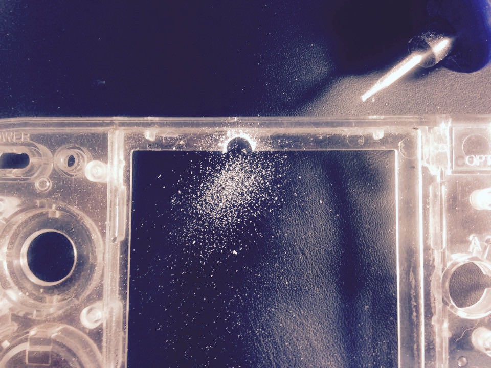
 Please leave a comment or question, your feedback is of big interest to me. that's all for today! Thanks a lot
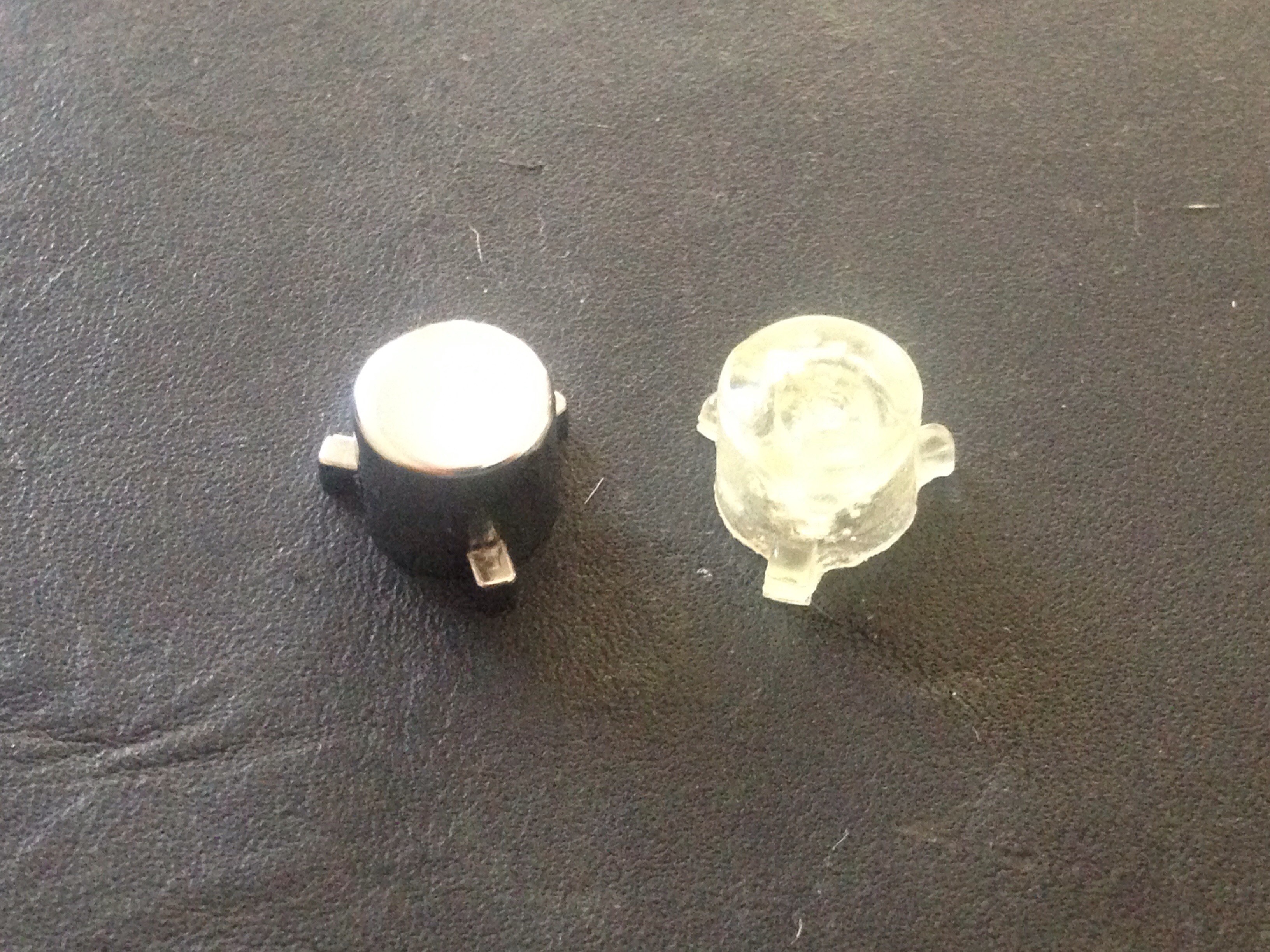
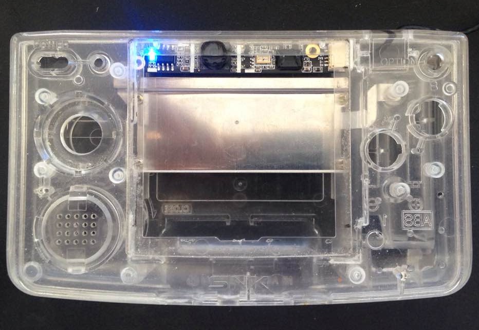
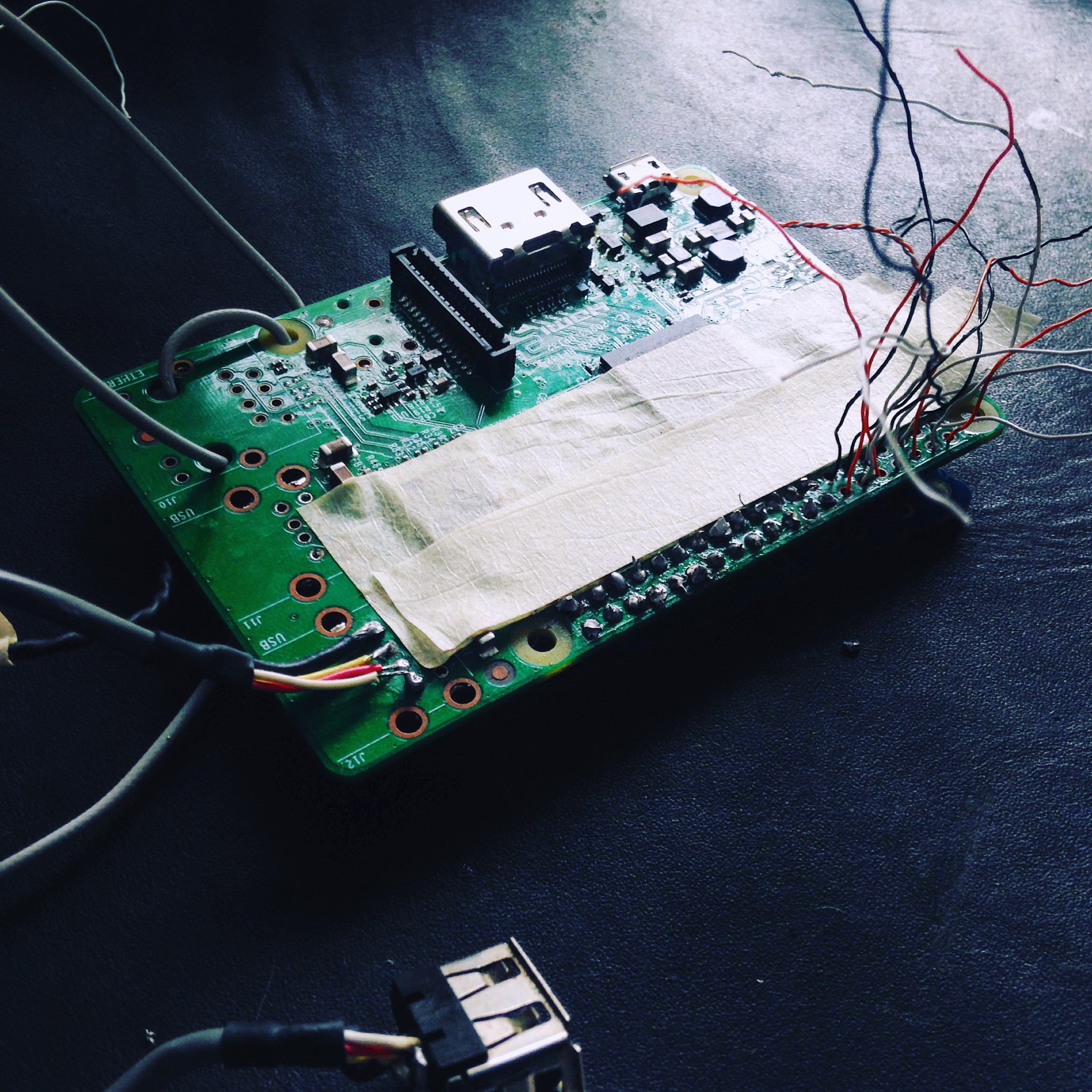
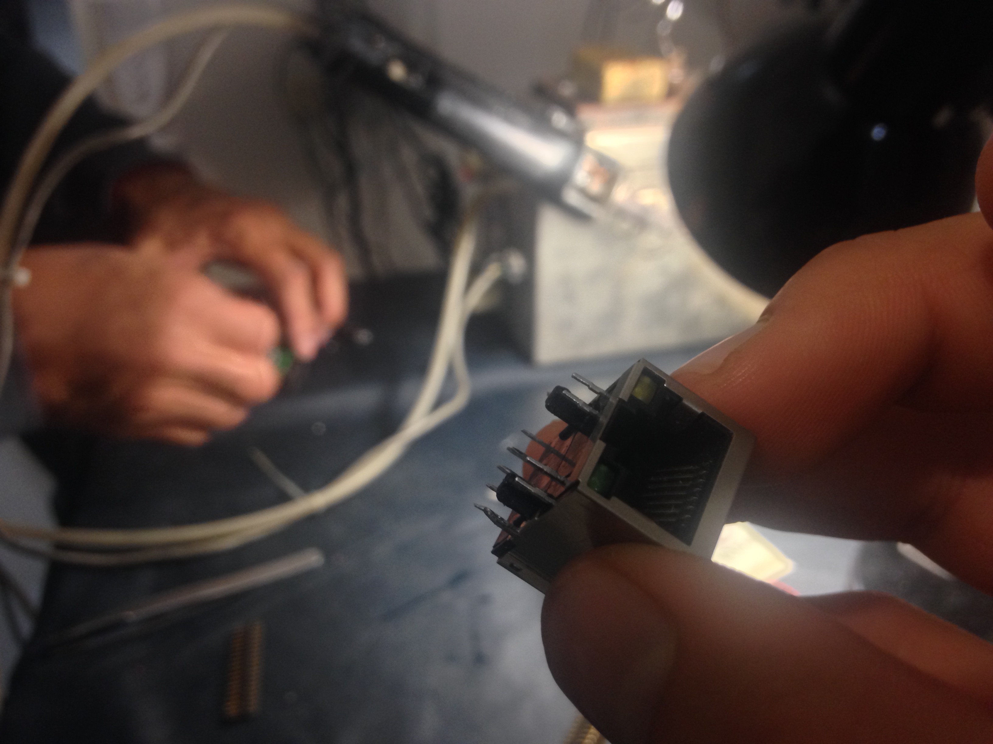
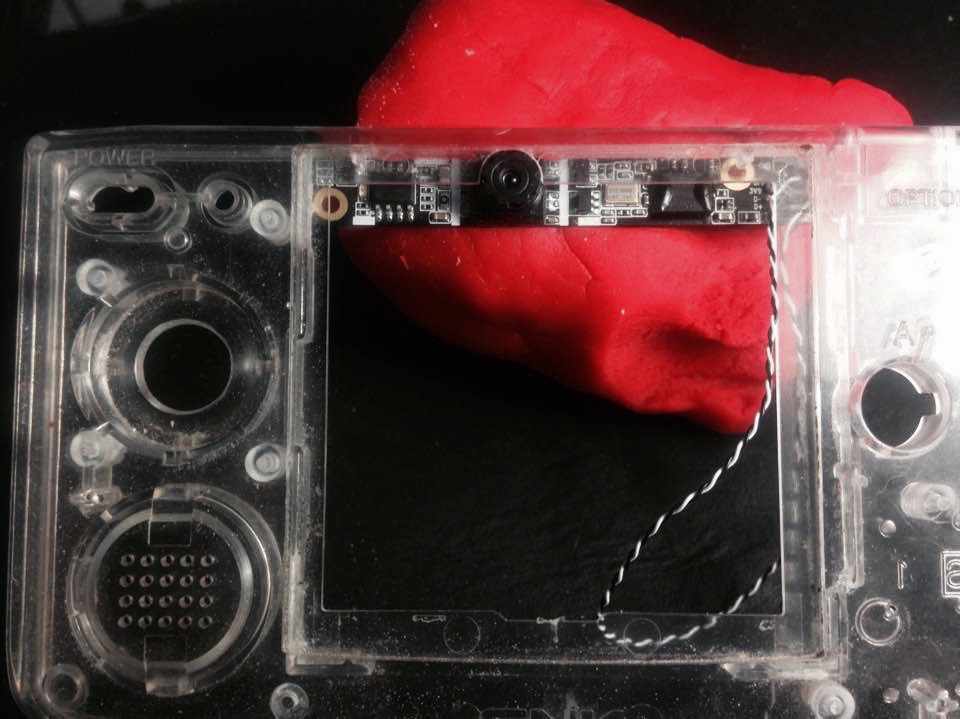
 here it is already modified:
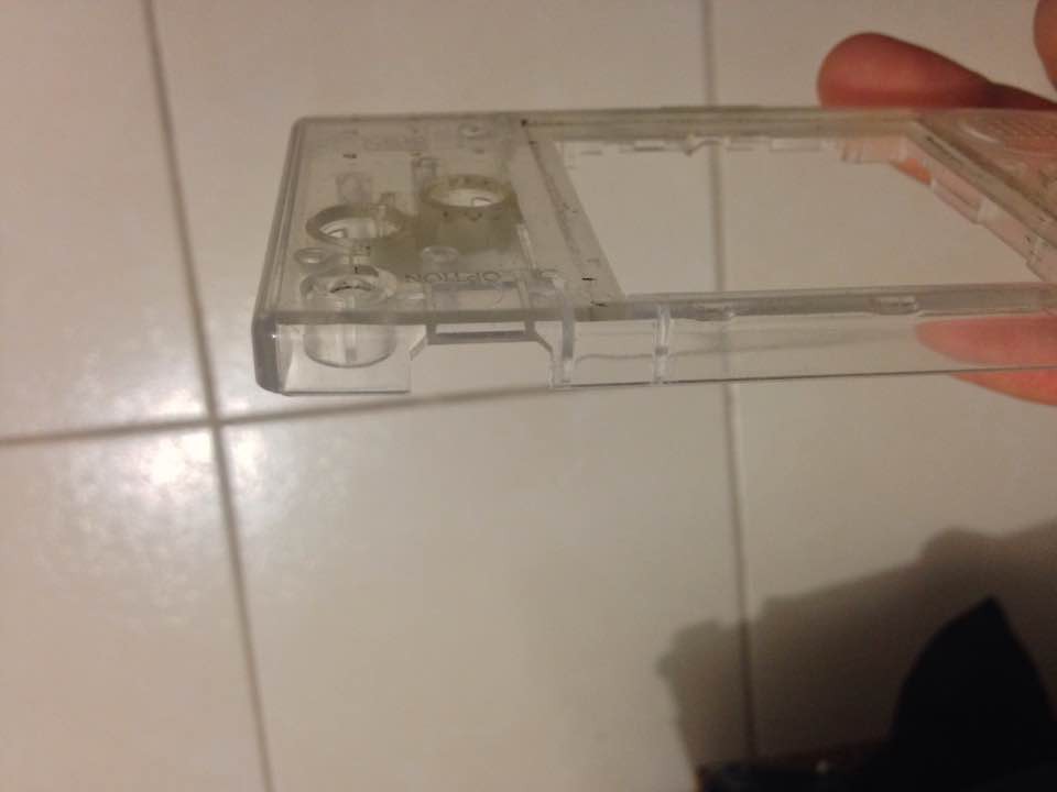
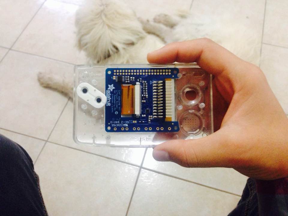
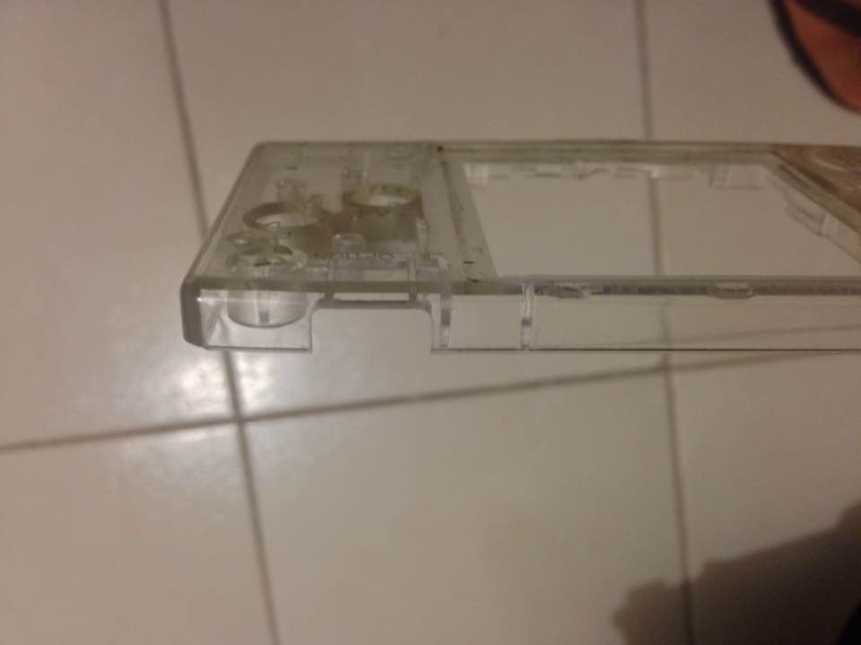 And here it is with the port in place (more less):
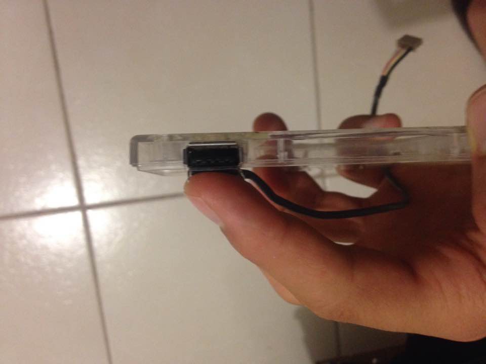 I'll be using a different cable for the USB, this one's too thick.
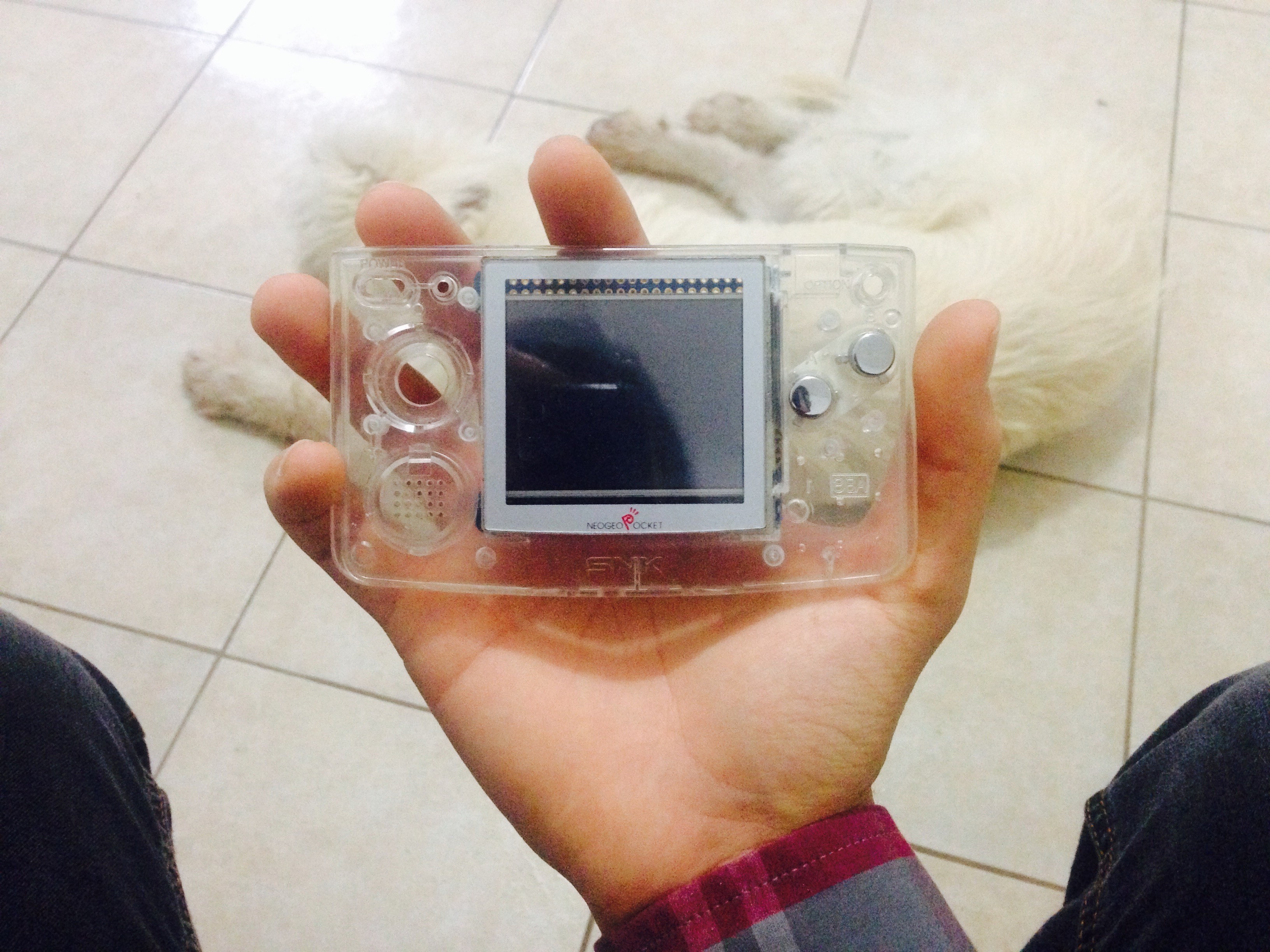
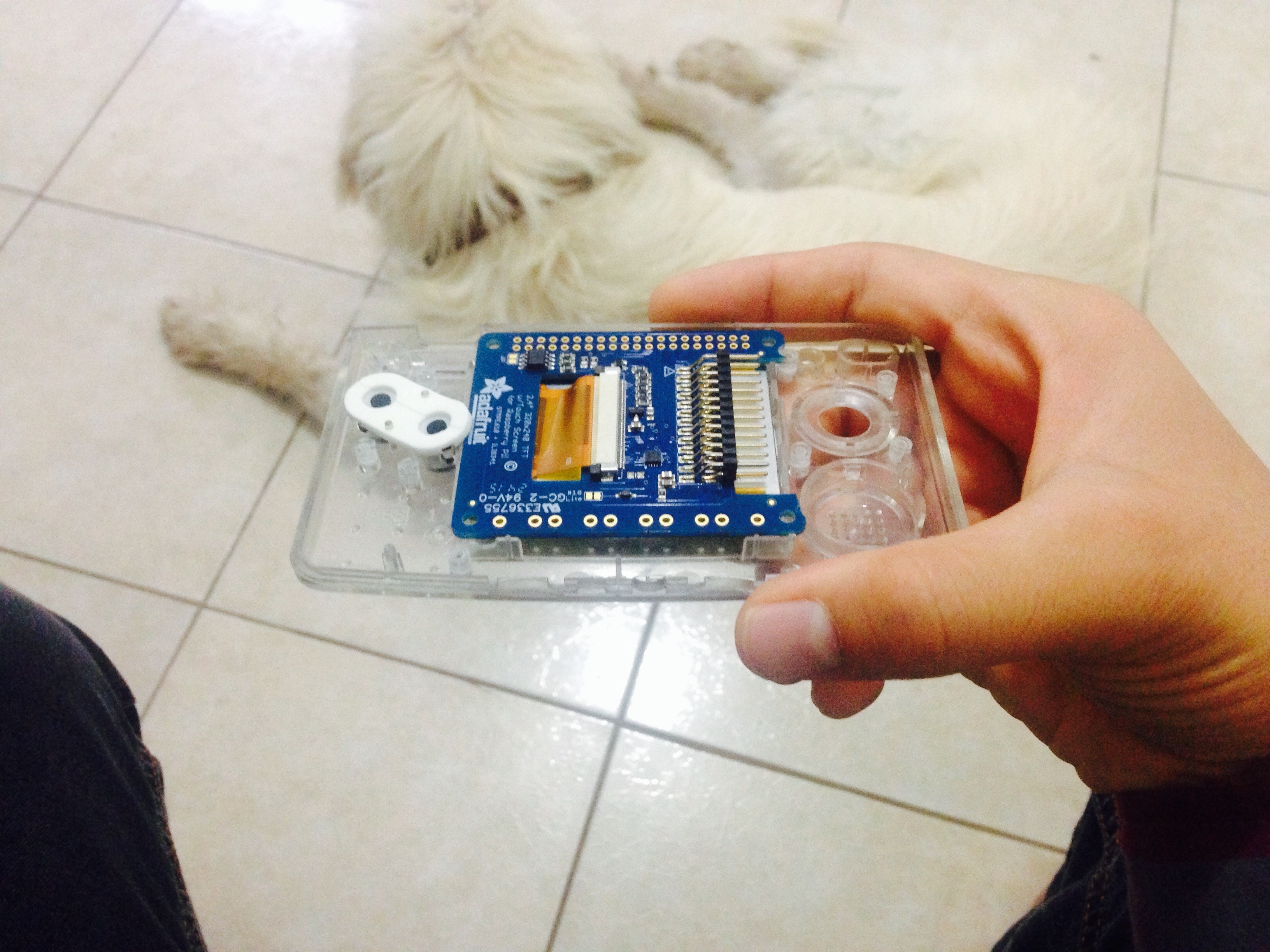
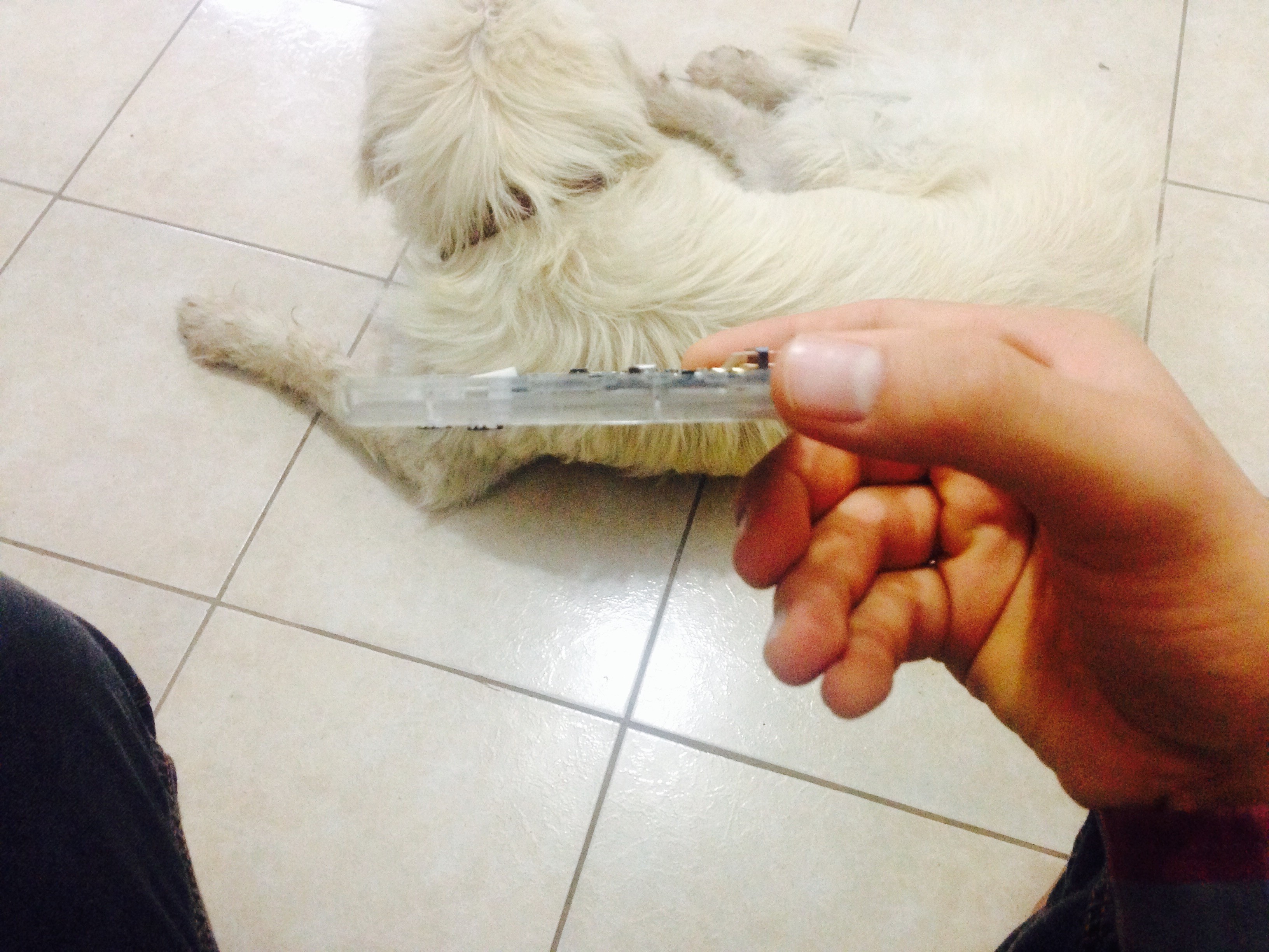
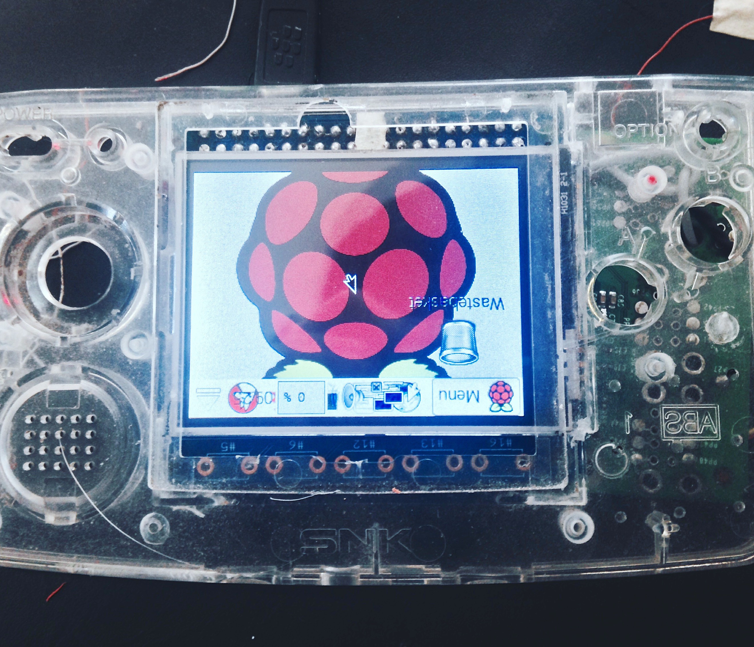
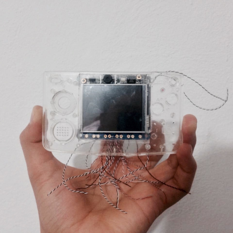
 So I guess this isn't bad for the first modification I make for this project, everything seems, fits and feels like it is meant to be. I'll keep you updated.
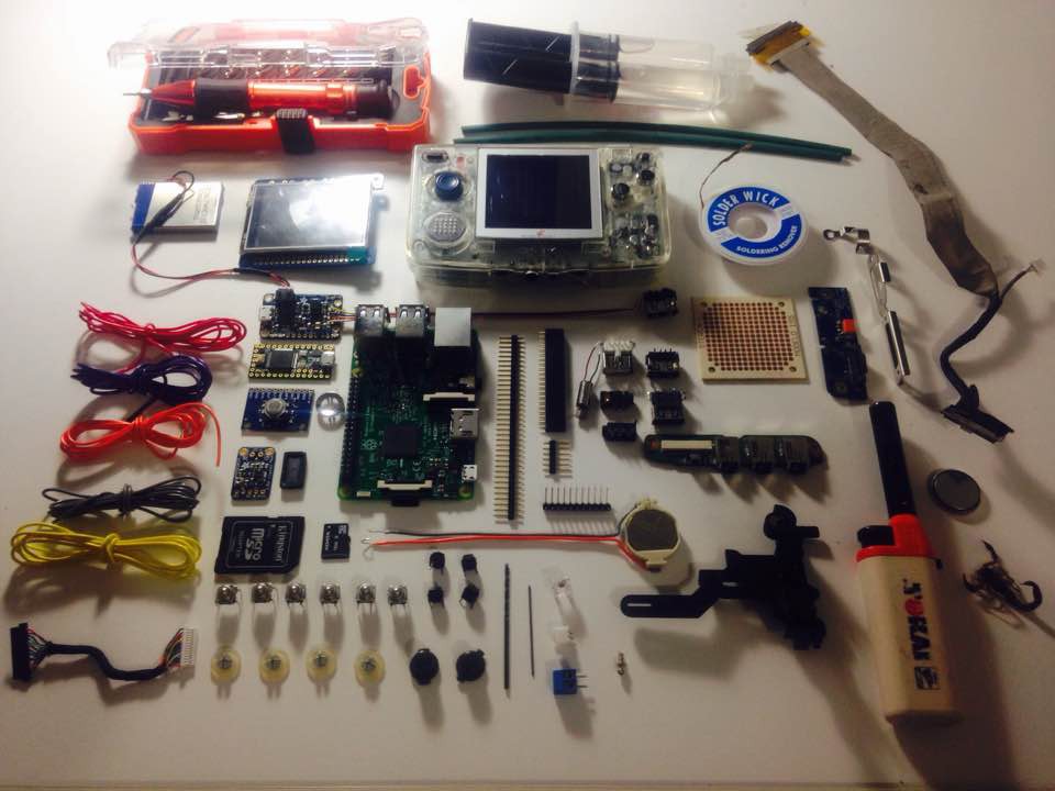

 origamimavin
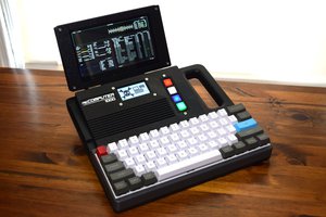
 Tom Nardi
 Andy
Andy
 Leonard
Hey there, something new ?? ;-)