 Chuck Glasser
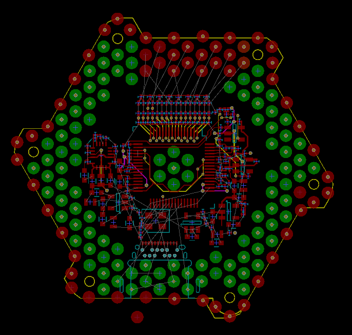
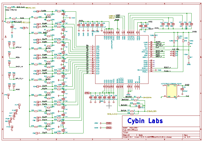
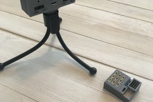
Cyince is a switched fabric network for processing large signal ensembles, in this case related to the brain/body. The number of signal sources and their individual bandwidths are arbitrary, limited in most cases by weight, primarily batteries, and not signal density. Sensors include the usual variety of electro physiological processes, MEMS accelerometers, gyros, force transducers, cameras, microphones, speakers, displays. In each case, the end point of the network will be either a sensor, or actuator that interfaces to the system via a specialized connector designed to support signal, power, and fluid transport.
The fabric is strictly peer to peer. While in many cases there is "host" as in a connected workstation that provides a convenient focal point for system configuration, data collection, analysis and study it is not necessary for operation of the device.
There are three primary applications of Cyince that are of major interest:
(1) As an infrastructure supporting a wide variety of prosthetic devices and/or (2) As a cyberspace deck for navigating the net without movement by thought alone. It is the movement in a virtual reality without a corresponding movement in physical reality that is THE problem. (3) As the primary signal process component in a new class of "Lab on a Chip" devices.
Before describing the instrument and it's architecture it may be useful to describe some of the harsh reality of biological signal processing.
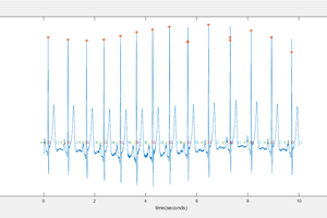
Basically you might think of the body as electrified salt water Jello. A signal generated, say from a muscle in the eye, may be measured everywhere. This is true for every other signal source. It's called the Cocktail Party. The challenge is to deduce an individual conversation from a ensemble of the same. Fortunately each of these conversations is separable using a process called Independent Component Analysis (ICA).
The control vectors are derived from a deep learning network that uses the EEG, EMG, and MEMS as inputs with a belief that there is a causal relationship between the three.
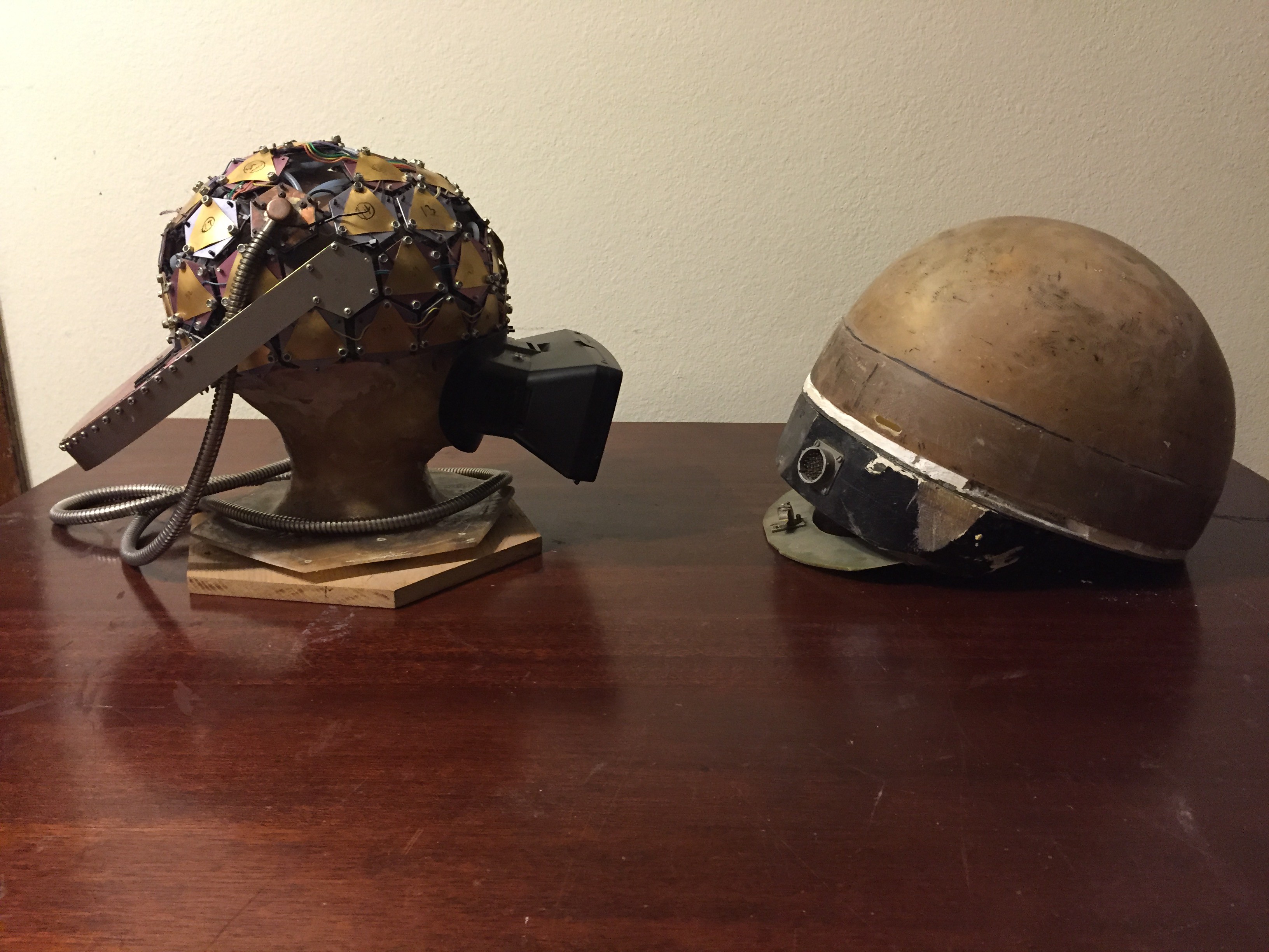
So, it seems that EEG sciences got themselves into a really bad habit. You see, back in the beginning, around 1926 when the very first 6-channel differential amplifiers based EEG systems were available, they were the size of desks. Experiments were performed with patients lying on beds. Then, some time around the 1960, people got civilized and started sitting in chairs wearing electrode caps with wires running off to a box. Unbelievably, over 50 years later, subjects are still sitting in chairs with caps and wires running off to a box. It is in fact iconic. The image, perhaps a artistic shadow image of someone sitting in a chair with electrode wires, streaming off their head, like a great mane of hair. Pretty image, freaking primitive way to process bio signals.
The challenge is to measure low level signals while going about your normal day. Walking, talking, driving, shopping, playing golf. That is the natural expression of the symbiosis between brain and body. I believe the effective study of the brain requires that the simultaneous measurement of movement is essential to understanding the entire being. So, if you want to build an effective neural prosthesis it is absolutely essential that you start with the study of complete working systems. Presently, this is not the case. I'd like to think that this problem persists because it is a hard problem.
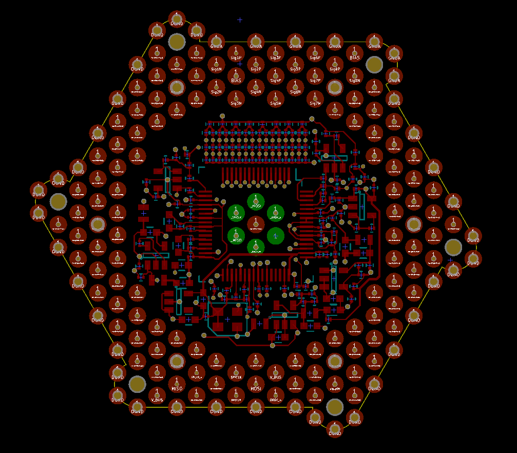
It's easy enough to measure 16 channels of pretty much anything. But how do you build an instrumentation system that supports thousands of channels of all sorts and descriptions, of all manner and type and signal level and impedances, and get it inside the memory space of a GPU with minimal latency while still being able to wear the device comfortably as though it were as ordinary as a pair of jeans?
Today we see countless examples of the application simple phenomena related to the EEG for simple controls. The most common application being alpha rhythm control. Eyes open...
Read more »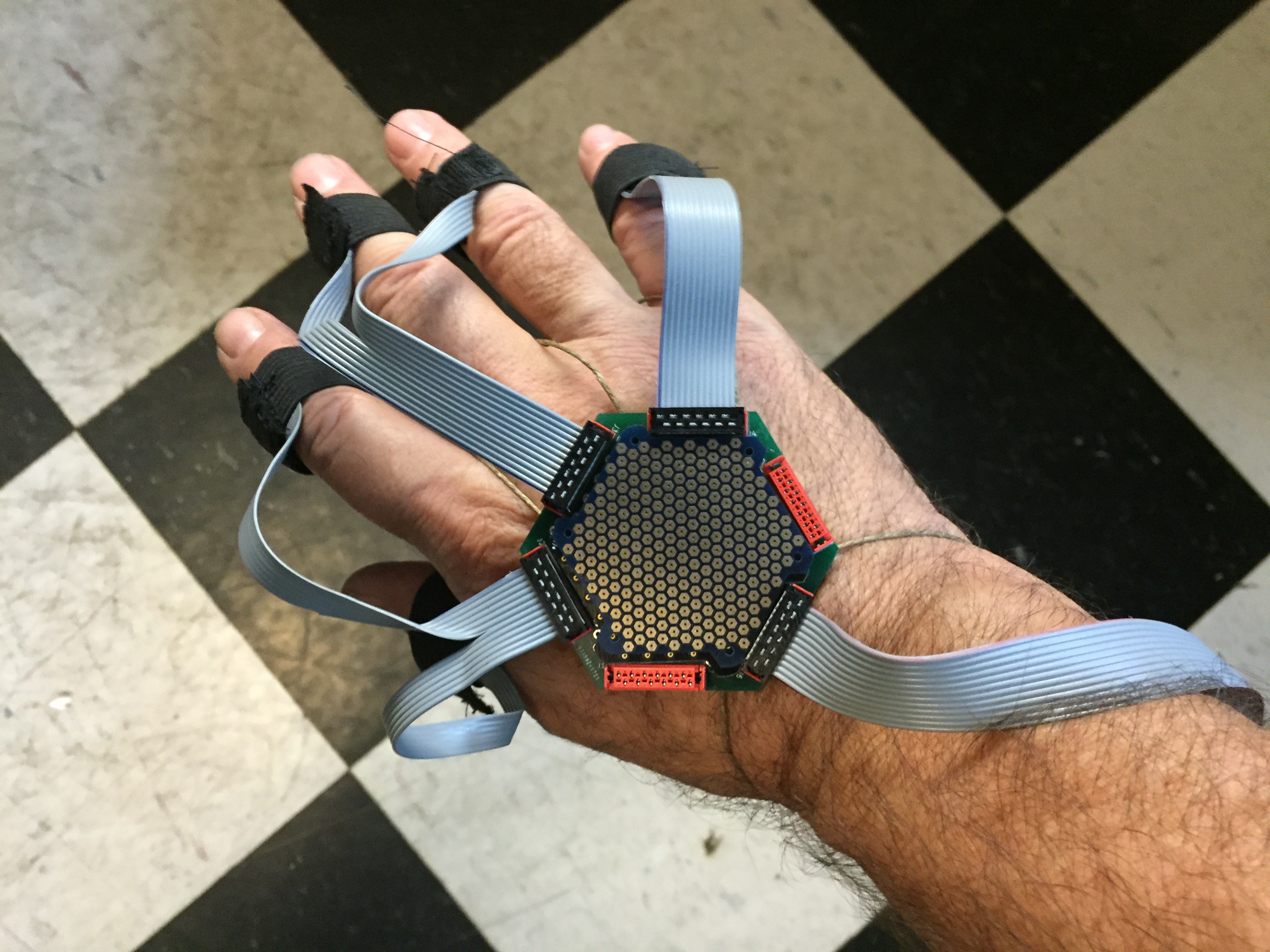
 Alex Lungu
 MS-BOSS
 Kenji Larsen