 mlo
mloMicrocontroller - Arduino Mega: We went with the Arduino Platform because we chose Adafruit Motor-shields to drive all the stepper motors.
Motor Driver - Adafruit Motor-shield V2: We went with this off-the-shelf solution because of it's ability to simply add additional motors by stacking shields. Since it communicates through I2C the wiring would be much simpler and it was cost effective.
Arduino Libraries - Accel Stepper: This library gave us the ability to simultaneously control multiple stepper motors. It also seemed to play nice with the Adafruit Motorshield.
Motor - 200 step/rev Bi-Polar Stepper Motor: We went with stepper motors because they had good accuracy, and reasonable balance between torque and speed. Conveniently, they worked nicely with the motor drivers, so this was an easy choice.
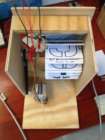
Card Holder - Laser cut Plexiglas: The card holder was the most important part of the design. Hand cutting wheels out of wood and drilling the individual holes in a drill press became tiresome quickly. Plexiglas was chosen because we thought it would stand the humidity better than wood.
Cards - Hand-cut Screen Printed CR-80 30mil PVC: My personal favorite design choice. These standard cards can be purchased for less than 10 cents a piece and gave us the durability and sound we needed. The material was easy to work with in terms of cutting them to spec and screen printing them.
Module Enclosure - CNC Baltic Birch: Accuracy and repeat-ability were key, so we needed to get the modules done through CNC. Baltic Birch was a step up from our original prototypes using Luon or Plywood, and could withstand humidity better.
Power Transmission - 2.5:1 Pulley/Belt System: It was tough to source out reasonably priced gears and I was concerned about how accurate we could install them. Pulleys and belts were a lot cheaper and my gearing ratio was driven by what was available through 3D Printer Suppliers.
Power Supply - 12V 30A Meanwell: Each bank of 16 Modules would pull around 12A. This power supply was reasonably priced and readily available through LED suppliers.
Home Sensor - Reed Switch and MCP23017: Mechanical switches were hard to position inside the individual modules. A reed switch with an adjustable magnet on the cardholder would allow us to calibrate each box. This still seems like the easiest and cheapest solution that has given us positive results so far. In addition, the MCP23017 I/O Expander was chosen because it communicated through I2C and conveniently gave us 16 inputs that could act as Pull-ups.
Wiring - CAT5 and Patch Panels: Individual connectors seems excessively expensive so I decided upon using a pre-built existing solution. I've read of people using CAT5 to transmit power in their LED installations, but made sure the the wires could support the power to the stepper motors.
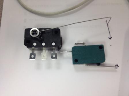
 With the sensor now positioned, when the magnet passed by the switch it would 'make' a connection to ground. This 'ground' signal would let the Arduino know to stop the Stepper Motor and reset all it's positional data.
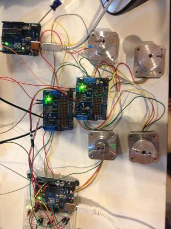 Now that I had the motors turning, it was time to construct the modules themselves! A workshop, some plans, and resourceful folk turned out the original versions. I won't go into too much detail about the dimensions until the later posts for the final design.
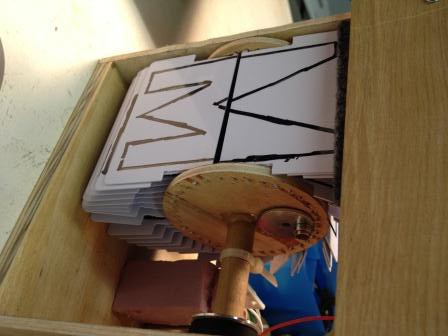
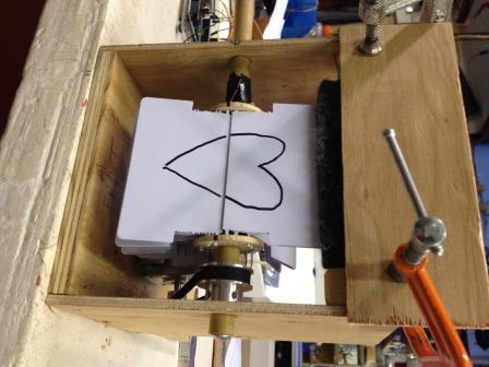 The card-holder are from 1.5 inch blanks found at Lowes. I was able to hand-drill 18 holes into two blanks. The cards themselves were carefully/poorly cut from a band-saw to some questionable dimensions. The initial prototype cards were printed with lovely permanent marker, it was sad that I had the best handwriting out of our group of three. The gray felt on top allowed us to adjust the amount of turns it took to display a single character.


 caver.adam
 Kenneth Zaborny
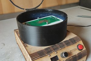
 Jeroen Delcour
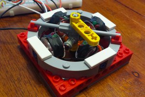
 Adam Smallcomb
I did I, but I can not do the software. Can you send me the code ?