Voja Antonic
There are three LEDs, the blue one for Low level, red one for High and yellow one for pulses, which are displayed as 200 ms flashes.
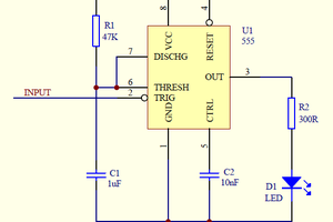
The open input is detected in an unusual way. Output A0 generates square wave output, which is fed to the probe tip via 330K resistor. In most cases, such a high impedance will not disturb the target system, and it can even locate its open inputs, as it will probably affect the system behavior. If the input A1 reads the same square wave, the input is open and all LEDs will be off. As the Interrupt-On-Change is used for detection, the short pulses will be detected in hardware level.
There is only one key which switches the probe ON, and the special "rising" sequence (blue-red-yellow) is displayed to notify that the probe is activated. Switching OFF is automatic, after 10 minutes, when it displays the "falling" sequence (yellow-red-blue) before going to sleep.
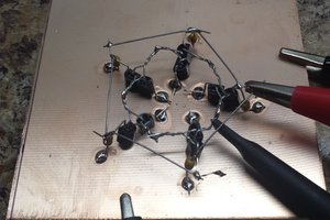
The probe tip is the ordinary needle for sewing. Well, the thick one. I was surprised to see how easy it is to solder it.
 Ted Yapo
 Tim
Tim