 willbaden
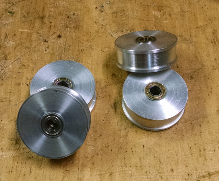
The Y axis linear guides do not use the plastic wheels of the original design. They now use rubber coated wheels. The wheels were made from a couple of rollers that were cut down. The ends were faced off to length in the lathe with a center hole opened up by boring out to allow for an interference fit on short segments of shafts (again from copy machines). These then ride in bearings that were also pulled from copy machines.
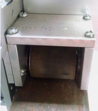
1/4" aluminum plate was used throughout this build and were also used in making the roller wheel carriages shown above. To contain the carriage, multiple rollers were used. Fixed top and side rollers were used on one side of the carriage.
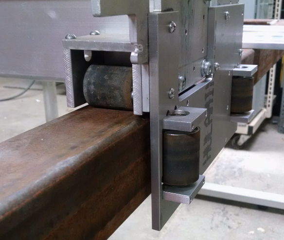
While the other side had a single spring loaded roller to maintain the carriage shifting left and right. In the picture below, the spring is on the left side and the fixed rotating axis of the lever is on the right. This is not a solid method to keep the X axis square with the Y axis travel. It gets by for now.
The carriage does not have rollers on the bottom to capture up and down movement. For the cuts that have been taken, the carriage weighs enough to hold it down on the steel tubing. At some point this should be updated to prevent creeping up of the carriage.
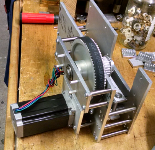
Now to the drive mechanism. Looking around the net shows that rack and pinion is the choice to use for CNC table anything, router, plasma, name your cut. Being concerned with price/mounting of the rack on the bottom, I opted for drive belts.
The carriage is driven on both sides to prevent large amounts of skewing of the X axis. Both sides use the same pulley ratio (3:1) prior to driving the linear belt. The way that the drive assembly mounts varies from side to side. Focusing on the right (left?) side.
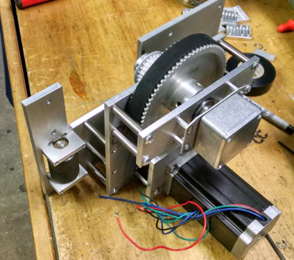
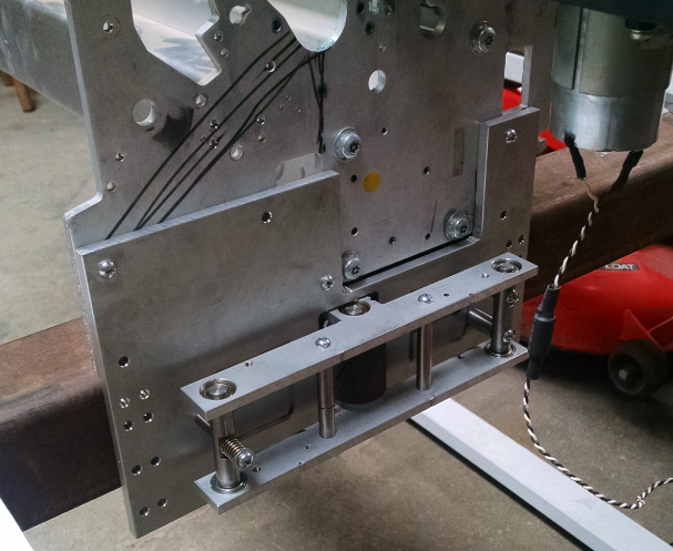
The stepper uses a 24 tooth pulley that drives the 72 teeth pulley above. The 72 teeth pulley is tied to a shaft that drives another 24 tooth pulley. The upper shaft can be seen above.
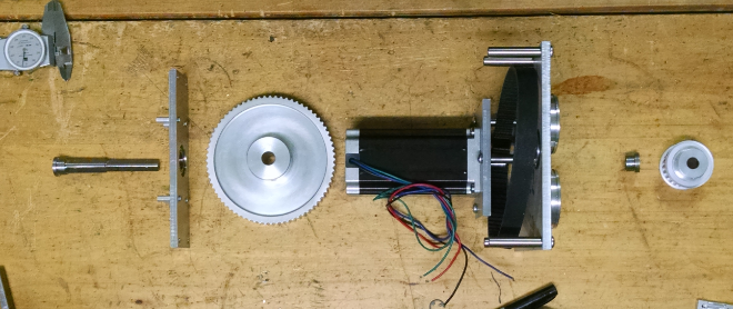
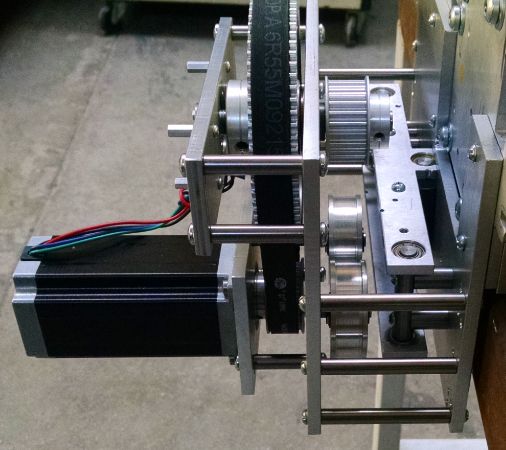
The picture above shows the upper shaft assembly spread out. Starting on the left is the shaft that feeds through the first bearing feeding through the 72 tooth pulley. Then feeds through the second bearing. A spacer is used on the second bearing to make up the gap between the shaft and bearing. Finally the drive 24 tooth pulley slips over the shaft. The pulleys are both fixed to the shaft with set screws. The shaft has flats milled where the set screws push against.
The picture above shows two idlers barely peaking out to the right of the motor. These slip over small shafts for the bearings to mate against.
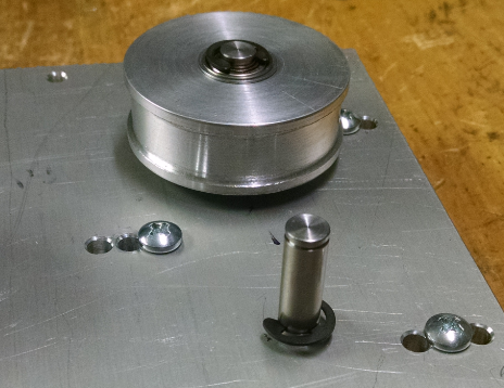
The idler pulleys were made from aluminum round. They were turned and faced to size. The center was opened up for an interference fit for two bearings on either side of the pulley.
Here are a couple more pics of the assembly.
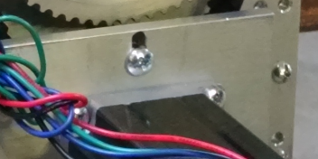
The belt tension adjustment between the motor and pulley is allowed by slots in the motor plate.
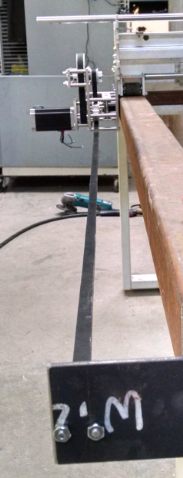
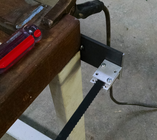
Mounting the cut belt on either side of the table was done by milling slots into a piece of aluminum at the pitch of the belt. This plate was mounted to a piece of angle with the belt sandwiched between.
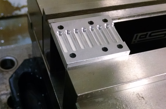
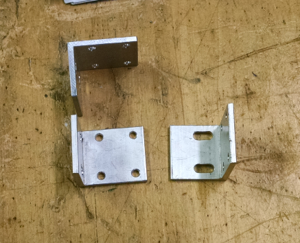
One belt clamp side is adjustable and the other is fixed. The fixed side worked good since it positively contacted the frame.
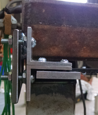
The adjustable side had issues with sitting at an angle.
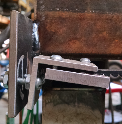
An upper angle piece was made to help pull the angle to 90 degrees with the frame plate.
Discussions
Become a Hackaday.io Member
Create an account to leave a comment. Already have an account? Log In.